Airborne Innovations Picoradio User manual

Picoradio Manual
720-515-3720
8 August 2018
Revision History
07/26/16 Initial version
02/2 /17 Added serial configuration
07/17/17 Updated safety precautions, radio options, serial port info, added mechanical drawing, long range
comms, ethernet switch info
08/11/17 Added technical note on J5 serial
08/08/18 Updated serial port pinout diagram
Airborne Innovations LLC

Airborne Innovations Picoradio Manual
Table of Contents
1 Introduction.............................................................................................................................................................3
2 Picoradio features....................................................................................................................................................3
2.1 Interfaces..............................................................................................................................................................3
2.2 Physical................................................................................................................................................................3
2.3 Radio options........................................................................................................................................................
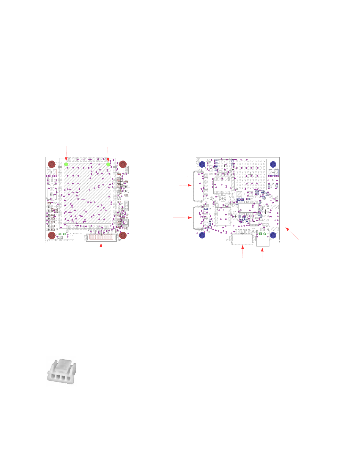
2. Connectors............................................................................................................................................................
2. .1 J1: Power Input.............................................................................................................................................
2. .2 J2: Auxiliary Power Output..........................................................................................................................5
2. .3 Ethernet connectors......................................................................................................................................5
J3: LAN ethernet connector (ETH0)....................................................................................................................5
J : WAN ethernet connector (ETH1)...................................................................................................................5
2. . J5: Serial connector......................................................................................................................................6
2. .5 S1: RS232/TTL mode DIP Switch...............................................................................................................6
2. .6 Technical note on the implementation of J5 Serial......................................................................................7
2. .7 J6: Secondary serial......................................................................................................................................7
2.5 LEDs.....................................................................................................................................................................8
3 Usage and Configuration.........................................................................................................................................8
3.1 Troubleshooting connections...............................................................................................................................8
3.2 Safety Precautions................................................................................................................................................9
3.3 Cooling.................................................................................................................................................................9
3. Radio usage..........................................................................................................................................................9
3. .1 Rx diversity...................................................................................................................................................9
3. .2 Dual transmission path and dual diversity....................................................................................................9
3. .3 Long Range operation................................................................................................................................10
3.5 Serial Port Configuration....................................................................................................................................10
3.5.1 Hardware serial port connection between two units - TCP........................................................................10
3.5.2 Hardware serial port connection between two units: UDP Point to Point..................................................10
3.5.3 Logical TCP connection to one remote serial port (easiest method to test with Pixhawk bidirectional
telemetry).............................................................................................................................................................11
3.5. Logical Point to Point UDP connection to one remote serial port.............................................................12
3.5.5 Other serial connection methods................................................................................................................12
3.5.6 Virtual Com Port drivers............................................................................................................................12
3.6 RF Amplifier Support.........................................................................................................................................12
3.7 Additional Ethernet Switch................................................................................................................................12
3.8 Mechanical Drawing..........................................................................................................................................13
3.9 Picoradio Cable/Antenna Kit..............................................................................................................................1
3.9.1 Picoradio_Picoraptor Ext Ethernet Cable..................................................................................................1
3.9.2 Picoradio Input Power Cable(one end cut).................................................................................................15
3.9.3 Picoradio Ext. Aux Power Cable (one end cut)..........................................................................................16
3.9. Antenna Cable, U.FL to RP-SMA-Female.................................................................................................18
3.9.5 2. GHz. Dipole ¼ wave Antenna, Connector, RP-SMA Male *.............................................................18
Page 2

Airborne Innovations Picoradio Manual
3.9.6 DC Power Female Jack to Terminal Block Adapter .................................................................................18
1 Introduction
This document is a manual covering features and usage of the Airborne Innovations Picoradio OEM board.
Warning: Make sure you read and follow the section 3.2, 'Safety Precautions' to avoid damaging the Picoradio.
2 Picoradio features
The Picoradio is based around the Microhard pDDL radio, an advanced broadband COFDM datalink capable of high
speed radio transmission and dual diversity receive. The board includes robust connectors, dual ethernet ports, and
a transparent serial port (with switchable RS232/3.3V TTL operation). The board also has an advanced wide input
range power system capable of operating from Lithium battery power, aircraft, or Power Over Ethernet voltage
ranges as well as an auxiliary power output to drive other devices. It is intended to be a complete full-featured but
minimum size replacement for the Microhard radio motherboard. Bandwidth of up to 25 Mbps is possible.
Advanced features such as mesh networking will be available in the near future. AES128/256 encryption available
(subject to control under the Export Administration Regulations,"EAR")
2.1 Interfaces
Interfaces on the board include:
•Wide range power input: 5-58V
•Auxiliary power output: 12V@2A+ (Some other output voltages may be factory configurable in the range
of 6-20V)
•Dual ethernet interfaces (LAN / WAN / bridged). These can act in a bridged configuration (i.e. as an
ethernet switch), or as independently configurable IP segments.
•Serial ports (one switchable 3.3V TTL/RS232, and one fixed 3.3V TTL). Note both ports are functional
(and have been since the initial release).
•Full set of LEDs (Power, Tx,Rx, LAN,WAN, RSSI x3)
•Reset button
2.2 Physical
Dimensions: 0x 0x10mm
Weight (with radio module) 17.6 grams
Page 3
Figure 2: Picoradio
board, approximately
actual si e
Figure 1: Picoradio si e
comparision

Airborne Innovations Picoradio Manual
2.3 Radio options
We can supply the 2. GHz version in an unencrypted version (our default option), or for domestic customers we can
supply the encrypted version (at the moment this may require a somewhat longer lead time). We are working on
availability of encrypted versions for international customers.
We have also built a limited number of dual 2. GHz / 900 MHz radios (without diversity). Contact us for
availability if interested.
A 1.8 GHz version may be available in the near future.
2. Connectors
Figure 3: Picoradio Connectors
2. .1 J1: Power Input
Power input uses a wide input range efficient buck-boost converter (Typical efficiency ~9 %). Input voltage range
is 5-58V (note for full RF power radio operation the minimum voltage may be limited to about 7-8V). Short pins 1,2
and 3, together for full current capacity.
Mating connector is a JST PA series latching connector:
Mating Connector: JST PAP-0 V-S
Contacts: JST SPHD-001T-P0.5
(Current rating is 3A per pin)
Page 4
J1
Power In
J2
Aux
Power
out
J3
LAN
Ethernet
J4
WAN
Ethernet
J5
Serial
J6
Secondar
serial
1 VCC In+
2 VCC In+
3 GND
4 GND
-
+
16
1
9
1 9
Rx Diversit
Antenna Port
Main Tx/Rx
Antenna Port
6
1
1
9
1
6

Airborne Innovations Picoradio Manual
Pin# Description
1 VCC In 5-58V
2 VCC In 5-58V
3 GND
GND
2. .2 J2: Auxiliary Power Output
Auxiliary power out is available from this connector. The default output is 12V. Current available depends on the
input voltage and RF output power setting of the radio (testing for your desired operating range is recommended).
Current available depends somewhat on voltage input and demand from the radio board. (for example, not including
the radio requirements, at 12V/1.7A output @ 6V in. 12V/3. A output @ 12V in, 12V/5. A output @ 2 Vin).
The radio uses approximately . W of power maximum from the second state regulator (which by default is taken
from the 12V supply, and does not take into account that the 2nd stage switcher is about 90% efficient).
The connector may be limited to approximately 2A. You can bypass the connector and solder directly to the board
for higher current (or test accordingly).
In some cases and for high volume customers we may be able to factory adjust the output voltage within the range of
8-20 volts (or even leave off this feature for a cost reduced version if you can provide 8-20V regulated input).
Mating connector is a 2mm pitch Molex connector (also compatible with JST PH series such as PHR-2):
Mating Connector: Molex 0873690200
Contacts: Molex 0502128000
Pin# Description
1 Aux Power Out
12V@ typically 2+
amps
2 GND
2. .3 Ethernet connectors
J3: LAN ethernet connector (ETH0)
J : WAN ethernet connector (ETH1)
These connectors have identical pinouts. The initial configuration connector is the LAN connector (right angle
connector on the board side opposite the radio). The WAN connector is the vertical connector on the same side as
the radio.
Mating Connector: JST GHR-09V-S
Page 5

Airborne Innovations Picoradio Manual
Contacts: JST MINI-SSHL-002T-P0.2
Pin# Description
1 ETH_1_T+
2 ETH_2_T-
3 ETH_3_R+
POE_Vin+
5 ETH_6_R-
6 POE_Vin-
7 NC
8 Link LED (disconnected by default- to connect a zero ohm
resistor needs to be placed)
9 GND
The ethernet connections are also labeled with their typical pin number in an 10/100 RJ 5 cable (1,2,3,6).
Note that a power input connection is available which may be capable of powering the radio board in some cases.
This is pseudo-POE (Power Over Ethernet)- power is not shared with data lines but it may be sent over the
connector, if the voltage is high enough to keep total current low enough for the connector and ethernet cable
(typically 8V). Do not connect unless using this feature – note they will also mirror the input voltage if powered
from the main input power connector.
2. . J5: Serial connector
This serial port can be configured as a transparent serial connection to a serial device, either with RS232 voltage
levels or 3.3V TTL voltage levels (with 5V tolerant inputs).
Note that the DIP switch S1 configures RS232 or TTL mode for this port.
Mating connector: JST GHR-06V-S
Contacts: JST MINI-SSHL-002T-P0.2
Pin# Description
1 VCC +5V out
2 RX (Serial input)
3 TX (Serial output)
RTS
5 CTS
6 GND
2. .5 S1: RS232/TTL mode DIP Switch
This DIP switch controls whether J5 operates in RS232 or 3.3V TTL mode.
Only one of the switches should be enabled at a time (do not turn both switches to ON mode).
Page 6

Airborne Innovations Picoradio Manual
SW1: Enables RS232 mode
SW2: Enables 3.3V TTL mode
2. .6 Technical note on the implementation of J5 Serial
J5 uses a TXS0108ERGYR voltage translator / buffer with open drain capability, and a parallel MAX32 3EEUI+
for switchable RS232 compatibility (with some added constraints due to this particular implementation). The
TXS0108 in particular has some unique features which put some constraints on operation. It can support open drain
as well as push-pull operation. The TXS0108 has no fixed input/output direction and so it attempts to auto-detect
transmit and receive direction. Pull-up resistors are integrated into the TXS0108, which can dynamically switch the
value of the pull-up depending on whether a low or high is being passed. Current sourcing capability for this port
is low (see TXS0108 datasheet) due to a series K resistor inside the IC (see TXS0108 datasheet). Our
implementation adds additional 120 ohm resistors in series with the external transmit and receive lines.
For more information please see: http://www.ti.com/lit/an/scea0 /scea0 .pdf and
http://www.ti.com/lit/ds/symlink/txs0108e.pdf
Due to the constraints of this switchable implementation and the TXS0108 hardware implementation, a loopback test
between TX and RX of the same serial port will need a pull-up resistor to function properly. A 1K pull-up to 3.3V
does allow this test to pass. Connecting the two pins directly without this may cause somewhat increased current
draw.
A serial loop between J5 and J6 works fine without a pull-up, as does interfacing to an FTDI interface, or our own
SBUS to serial and serial to SBUS interface modules, external GPS modules we have tried, and many other devices
we have connected.
We have reports that some Pixhawk hardware does not work with this port (with our original Pixhawk both telem1
and telem2 work fine with both J5 and J6, no pull-up required). Apparently all Pixhawks work fine with J6 (which
has simpler serial interface circuitry).
If you do need to get telemetry to a Pixhawk working over J5 (and the J6 workaround is not sufficient for some
reason), then you may have success with an external level translator such as those available from Pololu / Sparkfun.
2. .7 J6: Secondary serial
This connector is a second serial port (3.3V TTL only). The pin outs are the same as J5. The port is designated as
'USB0' in Microhard's interface.
This serial connector functions with the Pixhawk, and has a compatible pinout and identical connector for a Pixhawk
avionics to plug in with a straight through cable (disconnecting the VCC 5V output).
Page 7
Figure 3: RS232/TTL switch
(RS232 mode shown)

Airborne Innovations Picoradio Manual
2.5 LEDs
A number of status LEDs provide information on the radio status.
The RSSI LEDs provide a bar graph indication of relative signal strength (and if illuminating in a repeating 1,2,3
sequence indicate the radio is searching for a signal).
3 Usage and Configuration
The radio has its own IP address.
By default this can be accessed from the LAN ethernet port (ETH0 / J3), which is the right angle 9 pin connector..
The default IP address from Microhard is 192.168.168.1. By convention for Airborne Innovations systems we also
use IP addresses 192.168.1.201 (base station) and 192.168.1.210 (airborne). You can of course change these using
Microhard's web interface.
When the radios are first powered up the default user and password are both 'admin'. Microhard's firmware insists
on changing the password with a minimum of 5 characters so we change it to '99999'
To communicate with the radio it is easiest to set your PC to a fixed IP address such as 192.168.168.100.
You can then access Microhard's web page which allows changing radio settings.
To get two radios to communicate with our default configuration, we make these changes:
Base station IP address: 192.168.1.201
Base station mode: 'Slave'
Remote unit IP address: 192.168.1.210
Remote unit mode: 'Master'
WAN port set to bridging mode.
3.1 Troubleshooting connections
For a successful connection the following conditions must exist:
•Radios set up with different IP addresses (typically on the same subnet)
•One radio set for 'Master' mode (typically airborne/remote side)
•One radio set for 'Slave' mode (typically the base station)
Page 8
PWR
RED
3.3V CPU
BLU
RSSI1
GRN
RSSI2
GRN
RSSI3
GRN RX
GRN
TX
RED
ETH1
WAN
AMB
ETH0
LAN
AMB

Airborne Innovations Picoradio Manual
•Radios set to the same frequency
•Frequency changed from the default at least once (likely due to a Microhard bug)
•Encryption settings matching (Picoradios are typically supplied in an unencrypted version unless special
ordered with encryption so if communicating with an encrypted unit the encryption must be disabled).
•Antennas connected on both ends
•Sufficient RF signal strength (typically we operate at 23 dBm RF output power for lab testing).
•Reasonable RF band availability. Typically we operate on 2 79 MHz or nearby, which is slightly outside
the typical wifi band.
•Lastly some antenna separation may be needed (especially if operating at high power).
3.2 Safety Precautions
•Please note it is possible to damage Picoradios if they are not properly cooled. Please see the cooling
section below.
•It is also possible to damage the radio if you plug or unplug an antenna connection while it is powered (it is
very easy to short RF to ground when doing so).
•If using an RF amplifier it is possible to damage the RF front end of a nearby radio if you have too much RF
output power. Appropriate separation physical separation, power setting, and/or attenuation is required.
•Failures for these preventable issues is not covered by warranty.
3.3 Cooling
Some form of cooling should be used with the radio. Active cooling works extremely well- we find a small 0mm
fan with 7cfm flow works extremely well. Passive cooling with a properly sized heat sink can also work fine. You
may be able to use two smaller fans or find some other suitable method if integrating in a vehicle or enclosure (a
thermal pad interface to an enclosure or cool plate would also work). Please note that the RF module surface needs
direct heat removal. Also, if you are using accessory power, depending on the input voltage and power demands, the
power modules on the opposite side from the RF module can also generate significant heat (they are very efficient
but have high load capacity). As a result we recommend blowing air over both the radio module side (first priority)
as well as the opposite (power module) side.
Failure to cool the radios properly can result in radio failure or loss of connection.
3. Radio usage
There are some advanced ways to take advantage of the radio.
3. .1 Rx diversity
The 2. GHz version of the radio supports dual diversity receive. You can take advantage of this at the receive side
with dual antennas on the two different ports. This feature must be enabled in configuration and two antennas must
be connected if the feature is enabled. Transmit RF is emitted only from the 'Main' antenna port, and both ports are
used for receive when diversity is enabled. Note that the Main port is always bidirectional.
However there is a way to create two transmission paths:
3. .2 Dual transmission path and dual diversity
With a COFDM radio you can split the transmit power into two paths by simply adding a splitter and running the
signal to two antennas. You are cutting the power in half to each antenna (3dB down, plus the connector and cable
losses), but of course the total power output remains the same.
However the net advantage from having two transmission paths can be on the order of 10 to 15 dB, particularly for a
vehicle at range which is orbiting around its target and which may be pointing the null of one antenna at a time at the
base station, and/or which may be experiencing occlusions from the vehicle itself (i.e. the vehicle itself may at some
times block line of sight from one antenna at a time).
With 6 dB representing approximately a factor of two in range, the net 7-12 dB improvement can be a huge benefit.
More information can be found at www.microhardcorp.com
Page 9

Airborne Innovations Picoradio Manual
3. .3 Long Range operation
Please note that the distance parameter on the RF configuration page should be set to a larger value than you are
expecting to operate the radios at. It is also desirable for performance reasons not to set this to an excessively large
number. 0 km to 100km should be acceptable (but keep it as low as possible). There may also be issues if the
number is set too high (120 km).
We do have another document which addresses optimization for long range communications, please contact us for
this.
3.5 Serial Port Configuration
The serial ports are very flexible and can be connected to in a number of ways.
3.5.1 Hardware serial port connection between two units - TCP
This is an easy to configure hardware connection, which connects serial ports on two different radio modules.
An advantage is that data will never arrive out of order due to the TCP connection state.
It has some potential disadvantages in terms of connection and reconnection since it does have a connection state
(connected / disconnected). Below is a sample configuration which sets up a connection between COM1 of both
units.
Client side (base station 192.168.168.1): Server side (airborne 192.168.168.2):
3.5.2 Hardware serial port connection between two units: UDP Point to Point
This method would make sense for a connection needing realtime performance and a no-state connection (such as
our SBUS modules).
This configures a connection between COM1 of both units.
Base station 192.168.168.1: Airborne 192.168.168.2:
Page 10

Airborne Innovations Picoradio Manual
3.5.3 Logical TCP connection to one remote serial port (easiest method to test with Pixhawk bidirectional
telemetry)
This could make sense for an application which connects to the serial port using a TCP style connection (such as
MissionPlanner's TCP mode, or the telnet commandline tool).
To configure this method simply use the server side connection from 'Hardware serial port connection between two
units – TCP' above. Note that the base station serial configuration should remain unconfigured, i.e. should not
connect as a TCP client to the airborne port. To connect to the serial stream you make a direct TCP connection to
the airborne radio on the TCP server port.
Recent versions of firmware also have a TCP timeout, it may be necessary to increase this value somewhat from the
default.
Airborne i.e. 192.168.168.2:
Then you can telnet to the port, for example:
telnet 192.168.168.2 20002
or in the case of MissionPlanner you can the TCP connection method
Page 11

Airborne Innovations Picoradio Manual
3.5. Logical Point to Point UDP connection to one remote serial port
This method is also connectionless and allows an application to make a logical connection to a remote unit with a
serial port. Each side must be configured to communicate with the remote IP address and port number, and a listen
port which must match. Each side sends a packet to the other unit, with an IP address and destination port, and also
listens on a listen port. These port numbers can match or can be different. The key is the packet that is sent has a
destination address and port number. So each unit has to know the other side's IP address and listen port.
3.5.5 Other serial connection methods
There are also methods to connect via point to multipoint.
3.5.6 Virtual Com Port drivers
For applications which only understand hardware serial connections, you can use a virtual com port driver (which
would typically run on Windows or Linux). There are freeware and commercial drivers available. This makes the
logical connection and creates a virtual serial port on the PC which can be connected to exactly like a hardware serial
port on the PC.
3.6 RF Amplifier Support
The Picoradio may be used with a number of different RF amplifiers (regulatory issues apply and must be addressed
by the user). AI can supply an 8W bidirectional RF amplifier which can be used, and which autodetects the TX/RX
direction. We do have support for RF amplifiers which require TX/RX directional control as well (contact us if you
need this feature).
3.7 Additional Ethernet Switch
Picoradio has two ethernet ports which can function as an ethernet switch to connect and multiplex data from
multiple ethernet devices. However if you need more we can supply a miniature 5 port ethernet switch which can be
used with other devices such as our Pico series HD video encoders.
Page 12

Airborne Innovations Picoradio Manual
3.8 Mechanical Drawing
Page 13
Figure 4: Picoradio mechanical drawing

Airborne Innovations Picoradio Manual
3.9 Picoradio Cable/Antenna Kit
3.9.1 Picoradio_Picoraptor Ext Ethernet Cable
Page 14

Airborne Innovations Picoradio Manual
3.9.2 Picoradio Input Power Cable(one end cut)
Page 15

Airborne Innovations Picoradio Manual
3.9.3 Picoradio Ext. Aux Power Cable (one end cut)
Page 16

Airborne Innovations Picoradio Manual
PicoRadio Ext Serial Cable (one end cut)
Page 17

Airborne Innovations Picoradio Manual
PicoRaptor External Pixhawk Serial Cable
3.9. Antenna Cable, U.FL to RP-SMA-Female
No Drawing Available
3.9.5 2. GHz. Dipole ¼ wave Antenna, Connector, RP-SMA Male *
No Drawing Available
*Antenna provided is for short range and bench testing.
3.9.6 DC Power Female Jack to Terminal Block Adapter
No Drawing Available
Page 18
Table of contents
Popular Control Unit manuals by other brands

Gira
Gira 1019 00 installation instructions

Tyco
Tyco Varec 2440 Installation and maintenance instructions

WAGO
WAGO 750-481/040-000 manual

Cabletron Systems
Cabletron Systems FRM user guide

Sterling
Sterling Royal Series Operation and installation manual

CLA-VAL
CLA-VAL 50-20 Installation, operation & maintenance manual