Airborne Projects DROTAG User manual

AIRBORNE PROJECTS
DROTAG - Sony Alpha Series Image Tagging
Quick Start Guide
Airborne Projects specializes in building
drone solutions with emphasis on telemetry
gathering and integration with avionics and
automatic flight systems.
DroTag is a small board that simply sits
between your Sony Alpha Series
camera and your Pixhawk, allowing
you to plan the camera trigger events
and have the pictures taken automati-
cally geo-tagged on the fly.
Upon landing you only need to take out
the card from the DroTag board and
the images are immediately available
and ready to be visualized/used by your
mapping software.

Contents
1 Context 1
2 Assumptions 1
3 Package Contents 1
4 Hardware installation 1
4.1 Sony Alpha 5000 Specifics . . . . . . . . . . . . . . . . . . . . . . . . . . . . . . . . . . . 2
4.1.1 Tethering setting . . . . . . . . . . . . . . . . . . . . . . . . . . . . . . . . . . . . . 2
4.1.2 Focus Mode setting . . . . . . . . . . . . . . . . . . . . . . . . . . . . . . . . . . . 2
4.2 Setup your TELEM Port Parameters . . . . . . . . . . . . . . . . . . . . . . . . . . . . . . 2
5 Preflight Mission Planning 3
5.1 Time Between Pictures or "Photo every (est)" . . . . . . . . . . . . . . . . . . . . . . . . . 3
5.2 Trigger Method . . . . . . . . . . . . . . . . . . . . . . . . . . . . . . . . . . . . . . . . . 4
6 Flight Checklist 4
6.1 Flight checklist - Detailed Explanation . . . . . . . . . . . . . . . . . . . . . . . . . . . . . 4
7 In Flight Capabilities 5
7.1 Manual triggering from RC . . . . . . . . . . . . . . . . . . . . . . . . . . . . . . . . . . . 5
8 After Flight Capabilities 6
8.1 microSD card care . . . . . . . . . . . . . . . . . . . . . . . . . . . . . . . . . . . . . . . 6
8.2 File structure . . . . . . . . . . . . . . . . . . . . . . . . . . . . . . . . . . . . . . . . . . . 6
9 Troubleshooting 6
9.1 Significant delay in pictures . . . . . . . . . . . . . . . . . . . . . . . . . . . . . . . . . . . 6
9.2 Display is stuck "Camera USB Connecting" . . . . . . . . . . . . . . . . . . . . . . . . . . 7
9.3 Display is stuck on "Check Connect Device" . . . . . . . . . . . . . . . . . . . . . . . . . . 7
10 Further Information 7
Appendix A How to update DROTAG’s firmware 7
Appendix B Camera compatibility 7
Appendix C DROTAG Camera Configuration 8

1 Context
This User Guide’s goal is to get DROTAG working with your tethering camera and your APM based Flight
Controller module.
DROTAG is a small board that simply sits between your camera and your Flight Controller (like Pixhawk),
allowing you to remote trigger the camera (manual or automatically) and have the taken pictures auto-
matically geo-tagged. Upon landing you only need to take out the microSD card from the DROTAG board
and the images are immediately available and ready to be visualized/used by your preferred stitching
software.
Currently just the main Sony Alpha Series cameras were tested (A5000, A5100 & A6000), although it is
likely that many more tethering capable cameras are supported. Our product is based on libgphoto2 and
it’s camera compatibility list can be found in this link ;
This manual also features an appendix with the cameras tested and any relevant comments.
2 Assumptions
1. The DROTAG module is connected to one of the available telemetry output found on your flight
controller (Pixhawk/APM/NAVIO/etc);
2. The power to the DROTAG is supplied by the autopilot’s telemetry port;
3. The microSD card that came with your package is inserted in the DROTAG board. Another card
with the image supplied by Airborne Projects can also be used;
4. To get the pictures geo-tagged you need a GPS fix on your Autopilot. Without it, the camera
triggers manually and saves the picture but no additional tags are written;
5. The microSD card image you receive is bound to your DROTAG serial number. That means you
can use any microSD card you wish but you can only run it on your board. If you would like to run
DROTAG in another board contact us at our email;
3 Package Contents
1. DROTAG board;
2. 16GB Class 10 microSD card loaded with DROTAG software;
3. USB 3.0 microSD card Reader;
4. microSD to SD card Adapter;
5. DROTAG User Guide;
6. An Operation Checklist;
4 Hardware installation
Below you can find a picture illustrating the installation. We point out that good practices are advised re-
garding fixation of the board. Boards and Cables should be stowed clear of propellers in a vibration
resistant manner.
1

4.1 Sony Alpha 5000 Specifics
There are 2 camera settings DROTAG can’t change automatically, which are important for aerial photog-
raphy. The tethering setting and the focus mode. In the following instructions you will learn how to make
these one-time configurations to your Sony Alpha 5000 Series camera. The procedure for other Sony
Alphas are analogous although albeit with slightly different steps than the exemplified below.
4.1.1 Tethering setting
•Turn On the camera;
•Press the Menu button;
•Navigate to the Setup tile;
•Navigate-right, to page 2;
•On the USB Connection select PC Remote;
4.1.2 Focus Mode setting
•Turn On the camera;
•Press the Menu button;
•Select Camera Settings;
•Go to Page 3by navigating-right;
•Navigate and select Focus Mode;
•Navigate the options available until you find and select one saying MF;
•Rotate the lens ring until your camera says it is on ∞.
4.2 Setup your TELEM Port Parameters
This step is required to configure the TELEMETRY Port that you are willing to use your DROTAG board.
It only needs to be done once or any time you reset/refactor your parameters.
In the following instructions SERIAL1 prefix corresponds to TELEM1. If you would like to use TELEM2 the
applicable parameters are prefixed by SERIAL2. Accordingly, prefix SERIAL4 corresponds to physical
port TELEM4/5.
1. Connect your Flight Controller to Mission Planner (or equivalent);
2. Select the Config/Tuning tab;
3. Select Full Parameter Tree;
4. Find the command node SERIAL1 and set:
(a) SERIAL1_BAUD 57
(b) SERIAL1_PROTOCOL 1
5. Click Write Params
6. Power Cycle your Flight Controller boar in order to the changes take effect.
2

5 Preflight Mission Planning
DROTAG relies on APM messages to trigger the camera and add tags to it, so it is worth taking the time
to learn how to efficient mission planning. At Airborne Projects we do the planning of the mission and
waypoint upload through Mission Planner.
Although planning a mission in Mission Planner or others is outside the scope of this manual there are
some details that need to be taken into account. Specifically the "Photo every (est)" and the "Trigger
Method".
Other parameters and tutorials on Mission Planner can be found on this link. We seriously advise our
customers to get comfortable with tutorials as this part of the flight is the only one which is not automated.
5.1 Time Between Pictures or "Photo every (est)"
With the Sony Alpha Series, a full resolution JPEG picture with the advised settings never exceeds the
10 MBytes size. As the DROTAG needs to download the picture to process it, the "Photo every (est)"
parameter should not be less than 3 seconds. If the time between triggers in your mission plan is less
than 3 seconds some pictures may be missed or triggered out of turn, producing undesirable results.
To achieve always the best results, play with your mission parameters in order to achieve more than 3
seconds between photographs.
There are many ways around the "Photo every (est)" parameter, each with their own drawbacks. Below,
you can find the available approaches in order of best to worse:
1. Slightly Slower Flight - Your mission will take longer to fly but all your pictures will be with the
desired Ground Resolution (pixel/cm) which is the normal requirement parameter when doing aerial
photography.
2. Higher Altitude - When flying higher you can sacrifice Ground Resolution to obtain pictures with
bigger area covered. With bigger area covered in each picture, the more time you have to take next
one. You may hit a hard limit on both the altitude as well as on the Ground Resolution requirements.
3. Overlap or Sidelap reduction - It may be possible, due to end use of the collected pictures to
reduce the sidelap or overlap of the pictures so that they are less frequent. This increases the time
between pictures.
3

4. 2 passes - You can program the mission to perform the same flight path twice with a slight offset to
get the same overlap at the cost of extended mission time. This option is not available automatically
by Mission Planner and needs manually creating the mission waypoints.
5.2 Trigger Method
DROTAG requires the DO_DIGICAM_CONTROL Trigger Method in order to trigger the camera shut-
ter. This command should be executed every time a camera trigger is required. When drawing your
grid in Mission Planner you should define this command as default and all the trigger messages will be
automatically created according to your Survey Grid configuration.
As the actual trigger does not have any mechanical or analog component, there is no need to configure
any Servos or Relay pins. It is just simple as that.
If you want to know more about the Trigger Methods you should read this page.
6 Flight Checklist
Included in the DROTAG package is a checklist to perform before the flight. This checklist is not manda-
tory but is a good practice to guarantee that your field work will be flawlessly done.
1. Verify camera and cables are secure and away form the propeller’s path.
2. Verify the DROTAG has its microSD card inserted.
3. Power On the camera and check battery.
4. (Optional) Make shure that the camera settings are correct.
5. Power On the UAV general power.
6. Wait for GPS Lock.
7. Listen for 2 consecutive camera triggers.
8. The DROTAG system is ready-to-go! Have a nice flight!
6.1 Flight checklist - Detailed Explanation
1. Verify camera and cables are secure - This item is responsible for no damage or loss of equip-
ment. Not getting pictures is bad, destroying your hardware is worse.
2. Verify the DROTAG has its microSD card inserted - Without the microSD card inserted the
problem is 2-fold. The DROTAG software cannot run and it has no place to store your pictures. End
result is: your camera will do nothing.
3. Power on the camera and check battery - The camera should be powered before the DROTAG
board because the software running will not see any camera available. If the DROTAG board is
powered before camera it can be reset and it will try to check the camera again. Powering on
the camera is useful to check if there is any error in the camera. The battery check serves as a
situational awareness reminder. It is up to the operator to ensure the camera has enough battery
to perform the flight.
4

4. (Optional) Verify camera settings are correct - This is optional because the camera settings
should not change between flights. You should observer this item if the camera settings were
previously changed. Incorrect picture settings can make DROTAG under-perform severely because
some settings can cause the camera to have big delays between trigger and picture shooting,
blocking DROTAG while flight is carried on normally. Incorrect picture settings can also lead to
blurry, dark or white pictures. Standard guidelines to camera settings are given in the appendix.
5. Power On the UAV general power - This will power all the system as well as the DROTAG board
allowing it to take control of the camera.
6. Wait for GPS Lock - The APM needs to acquire a 3D Fix to have a position estimate. The position
estimate of APM is what enables coordinates tagging into the picture. The way you check for this
event is not the same in all the APM/GPS receivers. On the Pixhawk when the LED is green the
GPS is locked and this item is passed.
7. Listen for 2 consecutive camera triggers - The 2 camera triggers are a way for you to know that
DROTAG was able to take control of the camera, trigger it, download the image and write it in the
memory card. You can also manually trigger the camera if you have any channel in your Radio
bound to the camera action. This manual trigger will also record pictures.
8. DROTAG System is Ready-to-Go! - The operator can take-off and start the mission knowing the
camera system is working.
7 In Flight Capabilities
You can only interact with DROTAG in flight by associating an RC channel to Camera trigger. All other
interactions are automatically triggered by APM.
7.1 Manual triggering from RC
If you want to manually trigger DROTAG you can configure an RC channel to do it. For this follow the
instruction taken from Ardupilot documentation page for example for channel 7:
•Open Mission Planner and then click on CONFIG/TUNING | Full Parameters List;
•Set the value of CH_OPT to 9
•Write Parameters and reboot.
The camera should now trigger on channel 7 toggle.
5

8 After Flight Capabilities
8.1 microSD card care
The partition that is visible under Windows and that contains the tagged pictures, also contains hidden
boot files necessary for DROTAG to boot and start. If you blindly format the card you will also erase this
boot files needing to re-image the card, which is a time wasting effort. Reiterating DO NOT FORMAT
THE CARD IN WINDOWS. If you delete your pictures just delete the directories with single numbers on
it’s name, although any other files should be hidden. You can find out more in section 8.2.
8.2 File structure
When the Drone has landed the pictures are ready to be used and tagged with the geographical coordi-
nates. The structure of the card is organized by X/X_Y.jpg.
•Xis the directory name. It is a sequential number that increases each power-cycle of DROTAG.
DROTAG sequentially checks if the X directory already exists in the root of the microSD card. If it
does not exist a new directory is created and pictures will written to it. The prefix of Xin the file
name also makes the image have a unique file name, making it useful to track the same mission
waypoint over different flights.
•Yis a sequential number reflecting the number of the picture in a given DROTAG power-cycle.
To finalize with an example, take the following scenario: The SD card doesn’t have any directory and is
connected to the power once, executes a flight of 4 points and returns to base. When the operator takes
the card off the DROTAG board and inserts it into a card reader, the file structure should be the following:
9 Troubleshooting
9.1 Significant delay in pictures
This happens if the camera was not configured with manual settings. The automatic modes of the cam-
eras always take a certain amount of time find the correct settings. Not only can it take long for the
automatic focus to settle but it can also find that long exposure times are adequate. Possible actions are:
1. Follow the recommended setting provided in the appendix.
2. Abnormal behavior. Contact us.
6

9.2 Display is stuck "Camera USB Connecting"
When this happens it means the DROTAG is correctly booting but not taking over the camera. This may
mean that the main program is not running. Possible actions are:
1. View hidden files in the microSD card and try to check if the executable ./telepresence_gstreamer
is there. If it is not, you may have inadvertently deleted it. Please contact us.
2. Power cycle the DROTAG board and wait 30 seconds. The screen should disappear.
9.3 Display is stuck on "Check Connect Device"
This means the DROTAG did not boot at all even though the USB has power.
1. Verify the card is correctly seated in the DROTAG board.
2. Verify that all the hidden files are present: acme-arietta.dtb, boot.bin, full_gpio.dtb, OPERATION.LOG,
wpa_supplicant, zImage. If any of these are not present contact us so we can provide you with the
files.
10 Further Information
DROTAG relies on several open source projects. Airborne Projects takes open source licenses very
seriously and we have a public repository for the modifications made to the open source projects it relies
on, fulfilling the clauses of GNU Public License and Lesser GNU Public License where applicable. We
are not a company of lawyers so if we made any licensing mistake let us know so we can correct it as
soon as possible.
Appendix A How to update DROTAG’s firmware
new application binary. When you receive the application binary just copy it to the root of the microSD
card and replace the previous one. Nothing else should be necessary, unless an amend is published in
this manual.
Appendix B Camera compatibility
This is not an exhaustive list. It serves as a reference for the cameras we guarantee the DROTAG works
with.
Camera Model Minimum Time Between Pictures Can Raw
Sony A5000 3 seconds Yes
Sony A5100 3 seconds Yes
Sony A6000 3 seconds Yes
7

Appendix C DROTAG Camera Configuration
DROTAG has the capability of configuring the camera with specific settings when it starts. It is easy to
configure this settings.
Insert the DROTAG microSD card in your computer and inspect it’s contents. Look for a file called
AP1.conf and open it with your favorite text editor. In this file use the search functionality of your ed-
itor to find the word called camera_settings.
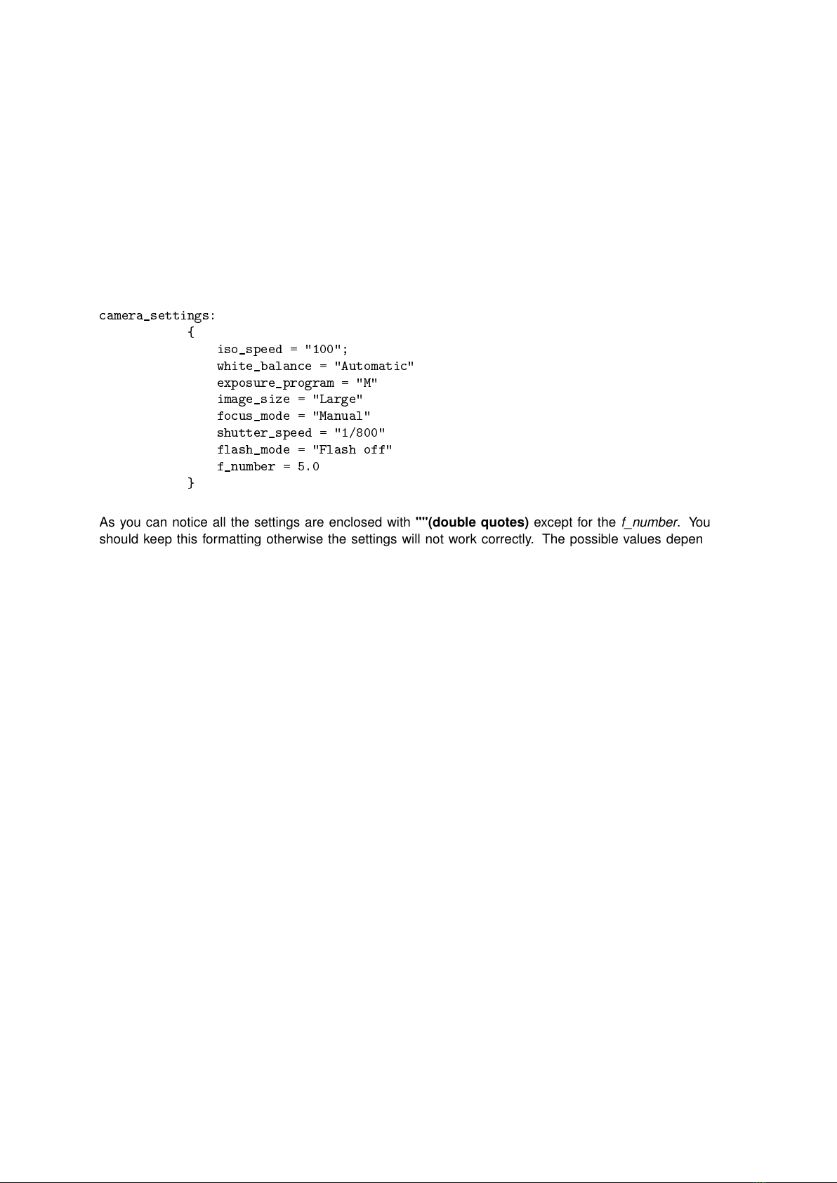
In this file section you will find many common photography parameters. Below is an excerpt of the default
settings pre-configured with DROTAG.
camera_settings:
{iso_speed = "100";
white_balance = "Automatic"
exposure_program = "M"
image_size = "Large"
focus_mode = "Manual"
shutter_speed = "1/800"
flash_mode = "Flash off"
f_number = 5.0
}
As you can notice all the settings are enclosed with ""(double quotes) except for the f_number. You
should keep this formatting otherwise the settings will not work correctly. The possible values depend
largely on which camera you are using. You can find how to get possible values for other cameras in the
appendix ??.
In the following section the possible values available for the Sony Alpha Camera Series are described.
•iso_speed - The sensitivity of the sensor to light. If the sensor is too sensitive to light it will capture
noise, or in our case pixels which don’t represent any scene data. A low value is desired so that the
noise is minimized, but enough sensitivity must remain to ensure the picture does not get "dark".
We recommend setting the iso_speed="320".
Possible values for the ISO Speed of the Sony Alpha Series are:
–25; 100; 125; 160; 200; 250; 320; 400; 500; 640; 800; 1000; 1250; 1600; 2000; 2500; 3200;
4000; 5000; 6400; 8000; 10000; 12800; 16000; 102400;
•white_balance - The white balance is setting that allows to relate how similarly white an object is
both in reality and registered in the picture. Sometimes this setting needs to be corrected.
We recommend setting white_balance=Automatic.
Possible values for the White Balance of the Sony Alpha Series are:
–Automatic; Daylight; Shade; Cloudy; Tungsten; Fluorescent: Warm White; Fluorescent: Cold
White; Fluorescent: Day White; Fluorescent: Daylight;
•exposure_program - This setting is specific to the camera and is a set of options for exposure
control.
We recommend setting exposure_program="M".
Possible values for the Exposure Programs of the Sony Alpha Series are:
–Intelligent Auto; Superior Auto; P; A; S; M; Movie; Unknown value 8051; Unknown value 8052;
Unknown value 8053; Unknown value 8054; Sweep Panorama; Portrait; Sports Action; Macro;
Landscape; Sunset; Night Scene; Hand-held Twilight; Night Portrait; Unknown value 8018;
8

•image_size - The size of the image. This a very general setting that may not be available in all
cameras.
We recommend setting image_size="Large".
Possible values for the Image Size of the Sony Alpha Series are:
–Large; Medium; Small;
•shutter_speed - The time the shutter stays open for a given picture trigger and is measured in
fractions of a second. Typically, the shutter speed for usage in drones should be very fast. This
makes the pictures look crisp and without motion blur caused by motion of the drone.
Depending on the lighting conditions we advise shutter_speed=1/3000.
Possible values for the Shutter Speed of the Sony Alpha Series are:
–You can choose any shutter speed provided it has a multiple of 10 in the denominator. A range
of tried shutter speeds are "1/20" to "1/3000", from slower to faster
•flash_mode - Self explanatory flash mode. There are several modes, but for flying purposes
flash_mode should be "Flash off".
•f_number - The ratio of the camera’s focal length and the diameter of the lens pupil. It mainly
affects picture depth of field, and which objects are in focus. For aerial photography the value
should be fixed, either at 5.6 or 8.0. Note that you can’t chose an arbitrary value. It depends on the
lens you are using. For more information on available F-Stops consult with this wikipedia page.
9
Table of contents
Popular Camera Accessories manuals by other brands

SteadyTracker
SteadyTracker CobraCrane UltraLite 1UL installation guide

AmpleNess
AmpleNess S52100G user manual

Moog Videolarm
Moog Videolarm RHW75 SERIES Specifications

Flyability
Flyability Elios 3 Safety Guidelines

Hyundai power products
Hyundai power products HYBAT40Li25 instruction manual

Sacred Sun
Sacred Sun FCP Installation and operation instruction