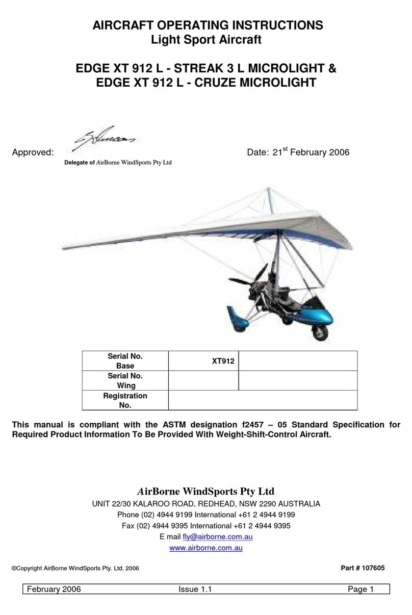
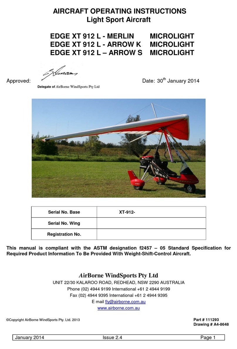
AirBorne WindSports XT 582 User manual

©AirBorne WindSports Pty. Ltd.
XT 582 Maintenance Manual
Issue 1.0
September 21st 2005 Page 1
XT 582
MAINTENANCE MANUAL
ISSUE 1.0
Manufacturer: AirBorne WindSports Pty Ltd
Unit 22/30 Kalaroo Rd
Redhead, NSW
Australia
Phone : + 61 2 4944 9199
Fax : + 61 2 4944 9395
Website : www.Airborne.com.au Part # 107282

©AirBorne WindSports Pty. Ltd.
XT 582 Maintenance Manual
Issue 1.0
September 21st 2005 Page 2
DATA PACKAGE
This manual constitutes one part of the complete data package that accompanies the aircraft. Following
is a list of each of the components which are required.
• Pilot’s Operator’s Handbook
• XT 582 Maintenance Manual
• XT 582 Illustrated Parts Catalogue
• Wing Maintenance Manual
• Wing Illustrated Parts Catalogue
• Rotax Owners Manual
• Rotax Maintenance (Compact Disk)
• Radio Manual – If Installed
• BRS Parachute Manual – If Installed
Table 1 XT 582 Data Package
+

©AirBorne WindSports Pty. Ltd.
XT 582 Maintenance Manual
Issue 1.0
September 21st 2005 Page 3
AMMENDMENT RECORD SHEET
Amendment Date Affected
Sections Affected Pages Date Inserted Signature
Issue 1.0
September 21st
2005
All of initial issue 1 to 102 September 21st
2005
Table 2 Amendment Record Sheet
NOTE
AirBorne’s data packages will be revised from time to time. Owners registered on AirBorne’s data base
will be notified of any changes to data and directed to the AirBorne web site
(<http://www.airborne.com.au/>) for the applicable pages. The amended pages should be printed and

©AirBorne WindSports Pty. Ltd.
XT 582 Maintenance Manual
Issue 1.0
September 21st 2005 Page 4
the prior page replaced in the folder as soon as possible. The amendment table should at that time be
updated with the appropriate details and date. Revised pages will be sent by mail if requested.
LOG OF ALL EFFECTIVE PAGES, ISSUE 1.1
Page Issue Date Page Issue Date
1-102 1.1 21/09/05
Table 3 Log Of All Effective Pages, Issue 1

©AirBorne WindSports Pty. Ltd.
XT 582 Maintenance Manual
Issue 1.0
September 21st 2005 Page 5
INTRODUCTION
This manual contains factory recommended procedures and instructions for ground handling, servicing
and maintaining the XT 582 Base section of this aircraft. The procedures described are to be used in
conjunction with the National Airworthiness Authority (NAA) of the country of registration. Any NAA
maintenance requirement takes precedence over this manual.
This manual will be used in conjunction with a certified wing, and therefore the operator is directed to
reference the wing maintenance manual for any issues that are related to the wing component of the
aircraft.
Skills
Only people with an adequate skill level should perform maintenance on this aircraft. A sound
understanding of mechanical systems, and good experience with the necessary tools and procedures is
required - as the continuing airworthiness of the aircraft relies on the competence of the person
performing the maintenance. Assessment and judgement of the condition of each individual component
is required, which necessitates a sound understanding of the purpose of each component in the
system. If there are any doubts regarding the required and appropriate maintenance then the safety of
the aircraft may be jeopardised in continuing with self maintenance. In this situation an Airborne Dealer
should be contacted for the correct procedures and or servicing.
All maintenance and repairs must be carried out in accordance with good aeronautical practices.
Tooling
There are no specialised tools (except for the air shocks) needed for the maintenance described in this
manual, following is a list of the type of tools that may be required. NB. Loctite will be required in certain
locations and should always be replaced after disassembly.
• Loctite (243, 567and Antisieze Lubricant # 76764) For the frame section.
• The Rotax Maintenance Manual gives a list of consumable materials in section 2.5.
• Open ended Imperial Spanner set
• Open ended Metric Spanner set
• Torque wrench
• Air Pump (Schrader Style Valve)
• Various petroleum lubricants
• Dry Lubricant – lubricant which doesn’t attract dust after application.
• Tie wire, and tooling
• Wire and Swages and tooling
• Hex key set
• Petrol resistant thread sealant tape
• Various general care items
This list may not be comprehensive.
Service Difficulty Reporting
Any service difficulties or defects should be reported to Airborne
WARNING
SPECIALISED PUMPS MUST BE USED FOR THE AIR SHOCKS – PRESSURES UP TO 600 PSI
EXIST.

©AirBorne WindSports Pty. Ltd.
XT 582 Maintenance Manual
Issue 1.0
September 21st 2005 Page 6
Format
The manual has been prepared using the ATA format, which provides a standard layout of the chapters
to be included, and their content. Some of the chapters are not included as they are deemed to be not
applicable to this aircraft.
The information in this manual is based on the data that was available at the time of its publication. The
latest amendments to this manual will be issued on the Airborne website in PDF format. This should be
printed out and added to the manual. Therefore it is important that operators keep a regular check on
the website for any amendments that have been made. If any errors or omissions are found in this
manual please advise the factory.
MANDATORY SERVICE BULLETINS
Note: This manual is based on the XT 912 manual. Some photos and illustrations show the XT 912
base.
WARNING
REPAIRS SHOULD NOT BE CONDUCTED UPON THE FOLLOWING ITEMS AS THEIR
STRUCTURAL INTEGRITY IS CRITICAL TO SAFETY.
THE MAST STRUCTURES, HANG POINT, BASE BEAM, FRONT FORK ATTACHMENT
ASSEMBLY, LANDING GEAR STRUTS.
OTHER MINOR REPAIRS CAN BE CARRIED OUT IN ACCORDANCE WITH FAA AC 43.13 1B
WARNING
THE INFORMATION IN THIS MANUAL NEEDS TO BE FOLLOWED, AND IT IS NOT
ACCEPTABLE TO MAKE CHANGES TO THE MATERIALS AND OR PHYSICAL FEATURES OF
THIS AIRCRAFT. IN PARTICULAR THE GRADES OF BOLTS THAT HAVE BEEN UTILISED IN
THE MANUFACTURE OF THIS AIRCRAFT ARE CRITICAL FOR ITS CONTINUING
AIRWORTHINESS. NEVER REPLACE BOLTS WITH ANY OTHER SIZE OR GRADE. GRADE 8
BOLTS ARE NOT INTERCHANGEABLE WITH AIRCRAFT (AN) GRADE BOLTS. THE FATIGUE
CHARACTERISTICS OF AIRCRAFT GRADE BOLTS ARE SUPERIOR TO OTHER BOLTS AND
ALLOW LONGER SAFE SERVICE LIFE UNDER CYCLIC LOADS LIKE THOSE EXPERIENCED IN
AIRCRAFT. THE LENGTH OF BOLT IS IMPORTANT. IF A SHORTER BOLT IS USED THE
THREAD MAY ENCROACH ON THE LOAD BEARING AREA, WHICH INCREASES THE
STRESSES EXPERIENCED BY IT.
AS THE SERVICE HISTORY OF THE AIRFRAME EVOLVES AIRBORNE WILL FROM TIME TO
TIME ISSUE MANDATORY SERVICE BULLETINS, WHICH DETAIL ANY CHANGES TO THE
MAINTENANCE MANUALS, PILOT’S OPERATING HANDBOOK, OR ANY OTHER DETAILS
THAT AIRBORNE DEEMS NECESSARY FOR OWNERS TO BE NOTIFIED OF.
THE WEB ADDRESS FOR SERVICE BULLETINS IS:
HTTP://WWW.AIRBORNE.COM.AU/
IT IS THE RESPONSIBILITY OF THE OPERATOR TO KEEP UP TO DATE WITH ANY ROTAX
DIRECTIVES THROUGH THE ROTAX WEBSITE.

©AirBorne WindSports Pty. Ltd.
XT 582 Maintenance Manual
Issue 1.0
September 21st 2005 Page 7
USE OF METRIC/ IMPERIAL UNITS
This Service Manual uses the metric unit system as the; basic system of measurement. Where
common usage or available instrumentation refer to, the Imperial system, both units are quoted. The
following conversion factors are presented as a ready reference to the conversion factors that have
been used in this manual.
1 Pound (Ib) = 0.4536 Kilogram (kg)
1 Pound per sq in (psi) = 6.895 Kilopascal (kPa)
1 Inch (in) = 25.4 Millimetres (mm)
1 Foot (ft) = 0.3048 Metre (m)
1 Statute mile = 1.609 Kilometres (km)
1 Nautical mile (NM) = 1.852 Kilometres (km)
1 Millibar (mb) = 1 Hectopascal (hPa)
1 Millibar (mb) = 0.1 Kilopascal (kPa)
1 Imperial gallon = 4.546 Litres (I)
1 US gallon = 3.785 Litres (I)
1 US quart = 0.946 Litre (I)
1 Cubic foot (ft3) = 28.317 Litres (I)
1 Degree Fahrenheit (F) = (1.8 X C)+32
1 Inch Pound (in Ib) = 0.113 Newton Metres (Nm)
1 Foot Pound (ft Ib) = 1.356 Newton Metres (Nm)
Table 4 Imperial / Metric Conversions

©AirBorne WindSports Pty. Ltd.
XT 582 Maintenance Manual
Issue 1.0
September 21st 2005 Page 8
CONTENTS
0. ASSEMBLY AND TEST FLIGHT / COMPONENT OVERVIEW ...................................................... 11
4. AIRWORTHINESS LIMITATIONS................................................................................................... 15
5. TIME LIMITS/MAINTENANCE CHECKS ........................................................................................ 16
6. DIMENSIONS AND AREAS............................................................................................................ 24
7. LIFTING AND SHORING ................................................................................................................ 26
9. TOWING AND TAXIING.................................................................................................................. 27
10. PARKING AND MOORING ........................................................................................................... 30
11. REQUIRED PLACARDS ............................................................................................................... 32
12. SERVICING................................................................................................................................... 33
20. STANDARD PRACTICES - AIRFRAME ....................................................................................... 40
23. COMMUNICATIONS ..................................................................................................................... 47
24. ELECTRICAL POWER.................................................................................................................. 48
25. EQUIPMENT/FURNISHINGS ........................................................................................................ 49
27. FLIGHT CONTROLS..................................................................................................................... 50
28. FUEL SYSTEM ............................................................................................................................. 51
31. INDICATING/RECORDING SYSTEMS ......................................................................................... 58
32. LANDING GEAR ........................................................................................................................... 60
34. NAVIGATION AND PITOT STATIC .............................................................................................. 65
53. FUSELAGE ................................................................................................................................... 67
55. STABILIZERS ............................................................................................................................... 71
56. WINDOWS .................................................................................................................................... 72
61. PROPELLERS .............................................................................................................................. 73
71. POWER PLANT ............................................................................................................................ 84
72. ENGINE MAINTENANCE.............................................................................................................. 86
73. ENGINE FUEL SYSTEMS............................................................................................................. 87
74. IGNITION....................................................................................................................................... 88
76. ENGINE CONTROLS.................................................................................................................... 89
77. ENGINE INDICATING ................................................................................................................... 91
80. STARTING .................................................................................................................................... 95
95. SPECIAL PURPOSE EQUIPMENT............................................................................................... 95

©AirBorne WindSports Pty. Ltd.
XT 582 Maintenance Manual
Issue 1.0
September 21st 2005 Page 9
LIST OF TABLES
Table 1 XT 582 Data Package............................................................................................................... 2
Table 2 Amendment Record Sheet........................................................................................................ 3
Table 3 Log Of All Effective Pages, Issue 1........................................................................................... 4
Table 4 Imperial / Metric Conversions.................................................................................................... 7
Table 5 Initial Assembly Procedure (GJP144) ..................................................................................... 11
Table 6 Airframe Limitations ................................................................................................................ 15
Table 7 Time Limits of Components .................................................................................................... 16
Table 8 Propeller and Gearbox Maintenance Schedule ....................................................................... 18
Table 9 Engine Maintenance Schedule ............................................................................................... 20
Table 10 Trike Base and Landing Gear Maintenance Schedule .......................................................... 21
Table 12 Torque Table ........................................................................................................................ 43
Table 13 Excerpt from GJP 141, Complete List of Tie Wire locations .................................................. 44
Table 14 Fuel Tank Schematic ............................................................................................................ 51
Table 15 SkyDAT Monitored Operations.............................................................................................. 91
LIST OF FIGURES
Figure 1 Main structural members ....................................................................................................... 12
Figure 2 Cockpit (XT 912 shown in photo) ........................................................................................... 12
Figure 3 Under-seat bags .................................................................................................................... 13
Figure 4 Mast Block Area (XT 912 shown in photo) ............................................................................. 13
Figure 5 Steering and foot levers......................................................................................................... 14
Figure 6 Power plant............................................................................................................................ 14
Figure 7 Front Mast to Mast Brace Check............................................................................................ 22
Figure 8 Major Dimensions (XT912 Shown) ........................................................................................ 24
Figure 9 Tie Down Hook Location........................................................................................................ 28
Figure 10 Front wheel with tie downs................................................................................................... 28
Figure 11 Tie on Rear Wheel............................................................................................................... 29
Figure 12 Trike on Trailer .................................................................................................................... 29
Figure 13 Parking of Trike (Upwind Wing Down) ................................................................................. 30
Figure 14 Securing of Base Bar With Bungee...................................................................................... 30
Figure 15 Parking Trike Tail to the Wind.............................................................................................. 31
Figure 16 Fuel Specifications............................................................................................................... 33
Figure 17 Air filter protection during cleaning....................................................................................... 37
Figure 18 Seat Mast Block Sub Assembly ........................................................................................... 40
Figure 19 Outside Nut with spat bracket .............................................................................................. 41
Figure 20 Inside Nut and Inner Spat Bracket ....................................................................................... 41
Figure 21 View of Locking Bolt head.................................................................................................... 41
Figure 22 Tie Wires on Propeller ......................................................................................................... 44
Figure 23 Rear Wheels Special Safetying............................................................................................ 44
Figure 24 Muffler Safety Wire and Springs .......................................................................................... 45
Figure 25 Mast Top Safetying.............................................................................................................. 45
Figure 26 Finger Filter, as installed, as well as the unit prior installation. ............................................. 53
Figure 27 Fuel Line Check Example .................................................................................................... 54
Figure 28 Fuel Flow Sender Device..................................................................................................... 55
Figure 29 Fuel Sender and tools.......................................................................................................... 56
Figure 30 Fuel Tap Bracket Sub Assembly.......................................................................................... 57
Figure 31 SkyDAT Console Photo ....................................................................................................... 58
Figure 32 Features of the Instrumentation ........................................................................................... 58
Figure 33 Rear Shock Dimension Check ............................................................................................. 61
Figure 34 Front Shock Set up .............................................................................................................. 62
Figure 35 Steering Damper Setting, (Dwg # 5610). ............................................................................. 62
©AirBorne WindSports Pty. Ltd.
XT 582 Maintenance Manual
Issue 1.0
September 21st 2005 Page 10
Figure 36 Front Wheel Assembly......................................................................................................... 63
Figure 37 Dynamic Port (Pitot Entry) ................................................................................................... 65
Figure 38 Top of Mast, attached to the wing ........................................................................................ 68
Figure 39 Front Landing Gear Attachment........................................................................................... 69
Figure 40 Front Fork to Wheel Attachment .......................................................................................... 69
Figure 41 Rear Landing Gear and Engine Mount Attachment to Mast Block........................................ 69
Figure 42 Pod Front Attachment.......................................................................................................... 70
Figure 43 Pod Attachment to Mast Brace ............................................................................................ 70
Figure 44 Pod Attachment to Seat Frame............................................................................................ 70
Figure 45 Pod Instrument Panel Attachment ....................................................................................... 70
Figure 46 AN4 Bolts Into Forward Hub Block....................................................................................... 74
Figure 47 Place Blades into Hub Block................................................................................................ 75
Figure 48 Propeller with all the necessary components ....................................................................... 75
Figure 49 Mounting the Propeller (Photo shows 912 engine)............................................................... 76
Figure 50 Propeller AN4 Bolt Tightening Sequence Numbers ...................................................................... 76
Figure 51 Propeller Part Lines ............................................................................................................. 77
Figure 52 Shims under the front wheel ................................................................................................ 77
Figure 53 Prop Hub at 89.95 Degrees after correct shimming of front wheel ....................................... 78
Figure 54 Propeller horizontal check.................................................................................................... 78
Figure 55 Radius Measurement........................................................................................................... 79
Figure 56 Setting the Blade (912 setting shown).................................................................................. 79
Figure 57 Propeller M8 Bolt Tightening Sequence Numbers................................................................ 80
Figure 60 Correctly Installed Propeller................................................................................................. 81
Figure 61 Engine Mount Rubbers (XT 912 Shown in photo) ................................................................ 84
Figure 62 Earthing of CHT Sender, to check the wire to the SkyDAT. ................................................. 92
Figure 63 Photo of screwdriver in place to remove wire....................................................................... 93

©AirBorne WindSports Pty. Ltd.
XT 582 Maintenance Manual
Issue 1.0
September 21st 2005 Page 11
0. ASSEMBLY AND TEST FLIGHT / COMPONENT OVERVIEW
00.00.00 Trike Base Assembly.
Table 5 Initial Assembly Procedure (GJP144)
This list is meant as a guide and is in no way a comprehensive list of instructions. Refer to Standard
Practices, Section 20 for torquing procedures and the Illustrated Parts Catalogue to ensure complete
and safe assembly is achieved.
Each of the components, which has been disassembled, have the required nuts, bolts and washers in
place - ready for fitment, this ensures that the reassembly is as easy as possible.
Line
Description
Ok
0 Caution: Mast has an air strut and will move quickly when untethered.
1 Remove straps and box.
2 Remove and unwrap all parts.
3 Remove mast support screws from the crate – leave the mast strap attached to support.
4 Remove front axel tie down bolts from the crate.
5 Loosen gearbox support rope.
6 Remove a frame bolts from the lower rear suspension pivots.
7 Use lifting mechanism such as a small hand winch to lift rear of trike to allow assembly of
rear end. Attach lifting device to the rear of the trike base tube and the top of the crate.
8 Fit Compression Struts (Rear end assembly).
9 Attach drag links ensuring they pass through the soft side holes.
10 Fit wheels and spat outer brackets. (Maintenance Manual Section 20.)
11 Lower trike wheels to the ground and remove lifting device.
12 Remove crate top, mast support and vertical legs. Remove crate base.
13 Fit the bottom rear shock struts to the engine mount.
14 Tighten all nuts and bolts according to Standard Practices, (Maintenance Manual Section
20.)
15 Fit Soft sides to cockpit. Ensure that the two buckles underneath the fuel tank are
fastened.
16 Attach mast brace inner tube to mast and tighten bolt (Wing Nut, Safety Pin) on the
bracket at the top of the mast.
17 Slide Outer mast brace sleeve over inner mast brace tube and raise mast. Secure outer
sleeve.
18 Fit rear wheel spats. (Maintenance Manual Section 20.)
19 Assemble prop and fit in accordance with Maintenance Manual Section 61.
20 Carry out pre-flight inspection in accordance with the pilot handbook.
21
Ensure the production flight test has been performed. Flight testing must be performed
by an authorised Airborne Dealer. Airborne form GJP 170 to be completed and returned
to Airborne by an Authorised Dealer.

©AirBorne WindSports Pty. Ltd.
XT 582 Maintenance Manual
Issue 1.0
September 21st 2005 Page 12
00.10.00 Component Overview
Important areas of the Trike base have been identified in this section to aid maintenance personnel.
These photos and list of names are not comprehensive.
Aircraft Structure
Figure 1 Main structural members
Cockpit
Figure 2 Cockpit (XT 912 shown in photo)
Mast
Se
at frame
Engine mount sub
-
frame
Base Tube
Front end assembly
Rear landing gear
Front pole
Mast/Seat block
Windscreen
Seats
Soft
-
side
Pod

©AirBorne WindSports Pty. Ltd.
XT 582 Maintenance Manual
Issue 1.0
September 21st 2005 Page 13
Under-seat bags
Figure 3 Under-seat bags
Mast Block Area
Figure 4 Mast Block Area (XT 912 shown in photo)
Under
-
seat bag (rhs)
Under
-
seat bag (lhs)
Inertia reel retractors
(mast padding not
shown)
Mast/seat block
Over
-
centre lev
er
Seat frame (top corner)

©AirBorne WindSports Pty. Ltd.
XT 582 Maintenance Manual
Issue 1.0
September 21st 2005 Page 14
Steering and foot levers
Figure 5 Steering and foot levers
Power Plant
Figure 6 Power plant
Brake park latch
Foot brake lever
Front foot steering pedal
Draft stop
Rear steering pedal
Dual steering linkage
Water radiator
Carburettors
Propeller
Reduction Drive
Fuel Tank
Radiator Over Flow
Muffler
Oil Injection Tank

©AirBorne WindSports Pty. Ltd.
XT 582 Maintenance Manual
Issue 1.0
September 21st 2005 Page 15
4. AIRWORTHINESS LIMITATIONS
4.00.00 General
This section sets forth each mandatory replacement time, structural inspection interval, and related
structural inspection procedure required for type certification.
4.10.00 Log of Effective pages – Airworthiness Limitations
4.20.00 Airframe Limitations
Component Life (hours) Requirement
Heart Bolt Bolt
(1 off)
50 Mandatory
Replacement.
(Drwg 5564)
Front Suspension
Pivot Bolts (2 off)
Rear Suspension
Pivot bolts (4 off)
200 Remove Inspect and
replace if necessary.
(Drwg 5590&5787)
Masts and Base
Tube
953 Check Service
Bulletins (See note).
Return to service if no
SB action required.
Trike Structure,
Excluding Masts and
Base Tube
Structures
8338 Check Service
Bulletins (See note).
Return to service if no
SB action required.
Table 6 Airframe Limitations
The airframe was analysed using FAA fatigue analysis “Fatigue Evaluation Of Wing and Associated
Structure on Small Airplanes FAA Report # AFS-120-73-2”, in order to estimate the time life limits for
the major components of the airframe, this is detailed in Airborne report 04-144ds. The estimates that
have been made do not take into account any extreme loads, which will reduce the fatigue life of the
airframe. The fatigue life of these components is dependent upon rigid adherence to maintenance
schedules.
The bolts that are listed are known through history of operation to be effected more through mechanical
wear than through fatigue, and therefore the time life for these components is less than the calculated
values for the airframe.
As the service history of the airframe evolves these time life estimates are expected to be revised,
amendments should be checked for regularly.
Note: See Airborne web site for service bulletin details

©AirBorne WindSports Pty. Ltd.
XT 582 Maintenance Manual
Issue 1.0
September 21st 2005 Page 16
5. TIME LIMITS/MAINTENANCE CHECKS
5.00.00 General
The time limits and maintenance schedule provided are in addition to any regulation of the governing
body where the aircraft is being flown. Some components are subject to overhaul intervals as specified
by their manufacturers, Table 5.10.00 gives the overhaul or replacement intervals for these
components.
The pilot of the aircraft must ensure that the required maintenance is carried out and documented in the
correct manner.
Extreme operating conditions may reduce the time limits for components, unscheduled maintenance is
detailed in Section 5.50.00. AirBorne will from time to time amend these maintenance checks as the
service history of the aircraft evolves. It is the responsibility of the pilot to ensure compliance with new
directives. (Information is available on the website www.Airborne.com.au)
5.10.00 Time Limits
The following components are time limited and should be overhauled or replaced as indicated. This
table may be updated to include more components in the future as MANDATORY SERVICE
BULLETINS are amended.
Component Life Requirement
Engine As specified by Rotax (www.rotax-
aircraft-engines.com)
Overhaul or Replace.
Engine Accessories As Specified by Rotax
(www.rotax-aircraft-engines.com)
Overhaul or Replace
Propeller As Specified by the manufacturer. See
section 5.20.10 of Maintenance Manual
Overhaul or Replace
Fuel and Oil Hoses Five Years or to be replaced during
engine overhaul – replacement
Replace
Rocket BRS As specified by BRS-5 Manual
6 years, return (parachute cannister
only) to BRS for repack.
12 years Rocket life.
(http://www.brsparachutes.com)
Repack parachute into
canister
Replace rocket
Table 7 Time Limits of Components
5.20.00 Scheduled Maintenance Checks
Airborne Microlights have been designed to permit easy inspection, and operators should have no
difficulty in assessing problems or recognising damage if visual checks are carried out correctly.
Maintenance checks may require partial disassembly of the aircraft. Inspection should include a
thorough visual check of the condition of the component and the attachment point in adequate lighting
conditions. Cleaning of the component may be required for proper inspection. Significant scratches,
cracks, galling or any other mechanical wear of the component is reason for replacement.
General care should include:
• Washing down the tube work with warm water and a mild detergent followed by rinsing with
fresh water.
• Fabric sponged with warm water and a mild detergent and rinsed with fresh water.
• The pod and wheel spats washed and polished using commercially obtainable shampoos and
polishes.

©AirBorne WindSports Pty. Ltd.
XT 582 Maintenance Manual
Issue 1.0
September 21st 2005 Page 17
• Treat all exposed metal components (including the engine) on the trike base (only) with a
dewatering compound such as WD40 or CRC spray. This guards against corrosion and makes
cleaning much easier.
• Lubricate the throttle cables regularly using light machine oil.
• The cockpit area should have all litter removed to minimise corrosion and to safeguard the
propeller.
Apart from the consequences of heavy landing, or of exceeding flight limitations, the major factors
requiring attention are corrosion, fatigue and wear.
There are no known fatigue problems with Airborne Microlights, but excessive loads and vibration can
weaken the structure. Regular inspection for hair-line cracks in areas under high stress, such as bolt
holes, tube junctions, etc is recommended.
Many components can be replaced with ease, for difficult repairs or if the repair process is not fully
understood consult your Airborne Dealer or the Airborne Factory.
The airworthiness of Microlights is only valid provided that all necessary Maintenance, Modification and
Service requirements are fulfilled.
These requirements include:
(a) Maintenance of aircraft as per the Maintenance Schedule in this handbook.
(b) Modification as detailed in any relevant Service Bulletins.
(c) Modification to approved details, obtained from Airborne WindSports Pty. Ltd.
(d) Repairs necessary to replace minor damage, wear or ageing.
(e) Servicing, replacement and overhaul, inspection and checking in compliance with the
Maintenance Schedule.
(f) Any Airworthiness Directory (AD) issued by CASA or the NAA of the country of registration.
Your micro light should be maintained in accordance with the following schedules.
Within these schedules the following codes are used:
Code:
1 Oil lubricate, clean and service.
2 Check as directed.
3 Check for insecurity, cracks, legibility wear and faulty operation.
4 Remove, inspect and replace if necessary.
5 Recommend replacement or overhaul.
6 Mandatory Replacement
Log Book
When maintenance is performed always check appropriate square. The hourly maintenance should be
dated and initialled on the appropriate maintenance schedule table.

©AirBorne WindSports Pty. Ltd.
XT 582 Maintenance Manual
Issue 1.0
September 21st 2005 Page 18
5.20.10 Propeller and Gearbox Maintenance Schedule
Section 12.20 should be consulted for more detailed instructions relating to this scheduled
maintenance.
Code:
1 Oil lubricate, clean and service.
2 Check as directed.
3 Check for insecurity, cracks, legibility wear and faulty operation.
4 Remove, inspect and replace if necessary.
5 Recommend replacement or overhaul.
6 Mandatory Replacement
The schedule is to be repeated for each subsequent block of 1000 hours
Table 8 Propeller and Gearbox Maintenance Schedule
WARNING
DISCONNECT SPARK PLUG LEADS FOR ALL MAINTENANCE AND INSPECTION
PROCEDURES!
ITEM MAINTENANCEREQUIREMENT
25 50 75 100 125 150 175 200 225 250 275 300 325 350 375 400 425 450 475 500 1000
Examinefor nicks and abrasions 2 2 2 2 2 2 2 2 2 2 2 2 2 2 2 2 2 2 2 2 2
Check security of blades 2 2 2 2 2 2 2 2 2 2 2
Check security and re-torque mounting bolts, &
sandwich plates. (Re-torque every2 hours for
first 10 hours)
2 2 2 2 2 2 2 2 2 2 2 6
Check adequate clearance between tip &
airframe
2 2 2 2 2 2
Rotate propeller to check out of track conditions
- 3mmmaximum at tips
2 2 2 2 2 2
Protective Blade Tape 3 3 3 3 3 3 3 3 3 3 3 3 3 3 3 3 3 3 3 3 3
Check hub section for cracks 4 4 4 4 4
Check Balance 4 4 4 4 4
CLEARPROP Placard 3 3 3 3 3 3 3 3 3 3 3
All welds 3 3 3 3 3 3 3 3 3 3 3
All Bolts 3 3 3 3 3 3 3 3 3 3 3
Oil Leaks 2 2 2 2 2 2 2 2 2 2 2
Breather Clear and Unobstructed, Tie Wire
intact
22222222222
Reduction Gearbox (Complete Overhaul at
1500hrs)
3 3 3 3 3 3 3
Bearingsecurity 2 2 2 2 2 2 2 2 2 2 2 2 2 2 2 2 2 2 2 2 2
DATE&INITIAL
Date and Initial Appropriate Box to record that
maintenance has been carried out.
AIRCRAFT or ITEM - HOURS OF OPERATION
REDUCTIONGEARBOX
PROPELLER

©AirBorne WindSports Pty. Ltd.
XT 582 Maintenance Manual
Issue 1.0
September 21st 2005 Page 19
5.20.20 Engine Maintenance Schedule
NOTE
The following Engine Maintenance schedules are of a general overview nature. The Rotax engine
Maintenance Manual should be used for specific maintenance required for the engine.
Code:
WARNING
DISCONNECT SPARK PLUG LEADS PRIOR TO ALL MAINTENANCE AND INSPECTION
ITEM MAINTENANCE REQUIREMENT
25 50 75 100 125 150 175 200 225 250 275 300 325 350 375 400 425 450 475 500
Overhaul (300 hrs or 3 years)
Check Rotax Website for Updates
22222222222
Oil leaks which could indicate cracks, blown
gaskets or seals
2222222222
Cylinders, finsandbaffles 3 3 3 3 3 3 3 3 3 3
All welds 3 3 3 3 3 3 3 3 3 3
LooseBolts 4 4 4 4 4 4 4 4 4 4 4 4 4 4 4 4 4 4 4 4
EngineRubber Mounts 3 4 3 5 3 4 3 5 3 4
Engine Platform, Mounting Plates Check for
Cracks
2222222222
Spark Plugs (CLEAN EVERYTENHOURS) 5 5 5 5 5 5 5 5 5 5 5 5 5 5 5 5 5 5 5 5
Spark Plugs andIgnitionHarness Secure 2 2 2 2 2 2 2 2 2 2
Crankcaseand mountinglugs free fromcracks. 2 2 2 2 2 2 2 2 2 2
Fuel Lines routed properly (free from abrasion,
heat & sharp edges) - fittings tight.
22242224222422252224
Fuel Tanklocated andsecure / no leaks or
cracks.
3333333333
Fuel Filter (SeeSpecial Instructions
Section 28.20.00)
5555555555
Fuel Pump (refer to Rotax Maintenance
Manual)
5
Throttle Cable (Few drops light machineoil See
Section 12.20.40)
13141314131413151314
AirFilter (See Section 12.20.50) 1 1 1 1 1 1 1 1 1 1 1 1 1 1 1 5 1 1 1 1
Check exhaust Portsfor Carbon Build-up 2 2 2 2 2 2 2 2 2 2
Mufflerand Exhaust Tubing 4 4 4 5 4 4 4 5 4 4
MufflerSprings 5 5 5 5 5
TieWires, See Section 20.20.00 3 5 3 5 3 5 3 5 3 5
Ignition switchON/OFF identification 2 2 3 2 2 2 2 2 2 2
Engineearthing cable 2 2 2 2 2 2 2 2 2 2
Carburettors(See Special Instructions Below) 3 3 3 3 3 3 3 3 3 3
Main CarburettorNeedles 4 4 4 4 4 4 4 4 4 4
Fuel Capacity Placard 3 3 3 3 3 3 3 3 3 3
Oil Capacity Placard 3 3 3 3 3 3 3 3 3 3
Fuel Tap Position Placard 3 3 3 3 3 3 3 3 3 3
EngineEarthing Placard 3 3 3 3 3 3 3 3 3 3
Exhaust Gas TemperatureOperation 2 2 2 2 2 2 2 2 2 2 2 2 2 2 2 2 2 2 2 2
Cylinder Head TemperatureOperation 2 2 2 2 2 2 2 2 2 2 2 2 2 2 2 2 2 2 2 2
EngineTachometer Operation 2 2 2 2 2 2 2 2 2 2 2 2 2 2 2 2 2 2 2 2
EngineHour meter Operation 2 2 2 2 2 2 2 2 2 2 2 2 2 2 2 2 2 2 2 2
Replace Engine Coolant (SeeSpecial
Instructions Below) (2-5years)
6 6
Replace Engine Oil (See Special Instructions
Below)
6 6 6 6 6 6 6
Cooling System Hoses (See Special
Instructions Below)
3333333333
Radiator Mounting Rubbers. (SeeAttach
Fittings Section 71.40.00)
3333333333
Expansion Tank. CheckLevel 2 2 2 2 2 2 2 2 2 2 2 2 2 2 2 2 2 2 2 2
Ground runat full throttle, note static rpm in log
book. If low check engine tuningand propeller
pitch settings.
2222222222
DATE & INITIAL
Date and Initial Appropriate Boxto record that
maintenance has been carried out.
AIRCRAFT or ITEM- HOURS OF OPERATION
ENGINE

©AirBorne WindSports Pty. Ltd.
XT 582 Maintenance Manual
Issue 1.0
September 21st 2005 Page 20
1 Oil lubricate, clean and service.
2 Check as directed.
3 Check for insecurity, cracks, legibility wear and faulty operation.
4 Remove, inspect and replace if necessary.
5 Recommend replacement or overhaul.
6 Mandatory Replacement
The schedule is to be repeated for each subsequent block of 500 hours
Table 9 Engine Maintenance Schedule
Time Limit for Rubber Parts
For checking the Engine Mount Rubbers, see “Mounts” Section 71.20.00, for other rubber components
related to the engine, see below.
See Rotax Maintenance Manual Section 10.
Time Limit for Coolant and Oil
See section 12.10.30 for Coolant details and section 12.10.20 for Oil details.
See Rotax Maintenance Manual Section 10.
NOTE
There are Special Instructions when using Avgas, Consult the Rotax Service Information 18 UL 97 D/E.
Time limit for maintenance Intervals
See Rotax Maintenance Manual Section 10
Table of contents
Other AirBorne WindSports Aircraft manuals

AirBorne WindSports
AirBorne WindSports Sting 3 Instruction Manual

AirBorne WindSports
AirBorne WindSports EDGE XT 912 L User manual

AirBorne WindSports
AirBorne WindSports FUN 160 Instruction Manual

AirBorne WindSports
AirBorne WindSports Edge XT 582-L Cruze User manual

AirBorne WindSports
AirBorne WindSports EDGE XT 912 L MERLIN MICROLIGHT Operating instructions