Aircatglobal VirtualFly SOLO-A User manual

SOLO A
USER'S MANUAL
Rev. .
January
FOR Cessna C172SP Skyhawk and Cessna Skylane II RG R182


3
SOLO-A USER'S MANUAL
TABLE OF
CONTENTS
1. IDENTIFICATION OF ELEMENTS
2. INSTALLATION
.. CABLE CONNECTION
.. INSTALATION OF FILES IN THE COMPUTER OF
MFS/PD
.. YOKO+ & VRNIO+ FLIGHT CONTROLS
CONFIGURATION
3. START-UP THE SOLO-A
4. SELECTION OF PANEL TYPE
5. RADIOSTACK PANEL
.. AUTOPILOT (AP) ‘KFC like’
.. COMMUNICATIONS AND NAVIGATION
.. DISTANCE METERING EQUIPMENT (DME)
.. AUTOMATIC DIRECTION FINDER (ADF)
.. TRANSPONDER (XPDR)
6. GPS GNS-530
.. KEY AND KNOB FUNTIONS
7. MULTIPLE SOLOFLIGHTPANEL OR MULTIPLE
MFS/P3D COMPUTER ON THE SAME
NETWORK
4
5
6
8
10
11
12
13
14
15
18
8. TROUBLESHOOTING
.. ANOMALY: THE INDICATOR PANEL DISPLAYS “MFS
Status: Searching...”
.. ANOMALY: CONNECTION GOES DOWN, IS
INTERMITTENT OR INDICATORS MOVES SHARPLY
9. TECHNICAL FEATURES
10. REMOTE ASSISTANCE
19
20
22
23

41. IDENTIFICATION OF ELEMENTS - SOLO-A USER'S MANUAL
1. IDENTIFICATION OF
ELEMENTS
Packaging contents:
. SOLO-A panel ( unit).
. SOLO-A Electrical power cable ( unit).
. SOLO-A Network cable ( unit).
. YOKO+ “the yoke” USB cable ( unit) (male, male A-B).
. VRNIO+ “throttle, propeller, mixture” USB cable ( unit) (male, male
A-A).
. SOLO-A Memory Stick (unit).
Content: SOLO-A_User's Manual, VF-TestCalibrate, VFConnect,
GNS-530E Network Module, GNS530_pilotsGuide, FSUIPC and
TeamViewer.
. SOLO-A Quick Start Guide ( unit).
It is important to save all parts you are not going to use, in case you need
them in the future.

5
2. INSTALLATION - SOLO-A USER'S MANUAL
2. INSTALLATION
The SOLO-A, has been technologically developed to be fully
plug&play. It connects easily to any computer running the “Microsoft
Flight Simulator” or “PreparD” hereinafter referred to as “MFS/P3D”.
Still, we’ll give you a series of steps to follow to install your panel.
The user must consider that SOLO-A has important modules::
• Thepanelitself:switches,gaugesandradiostack
• YOKO+“Theyoke”.
• V3rnio+“Throtlle,propeller,andmixture”.
• TheGPSGNS-530.
To activate all panel modules, the user must undertake operations:
• Cableconnection.
• InstalationoflesinthecomputerofMFS/P3D.
• YOKO+&V3RNIO+ightcontrolsconguration.
.. CABLE CONNECTION
Attention: before starting, the red back switch must be in OFF.
The user has options to connect the network cable:
• Direct(option1).
• Throughlannetwork(option2).
Once you finish, the user must connect the cable to the plug.
MFS/P3Dcomputer
MFS/P3Dcomputer
Home router
Switch OFF
Switch
OFF
OPTION 1: Direct
OPTION 2: Through LAN Network
Cable4
Cable4
Cable3
Cable3
Cable5Cable5
Not supplied
cable
Cable2
Cable2

62. INSTALLATION - SOLO-A USER'S MANUAL
2.2. INSTALLATION OF FILES TO THE COMPUTER OF MFS/P3D
FSUIPC Installation
In case you already have FSUIPC installed in your MFS/Prepar3D you
can skip this step.
• Go to the “FSUIPC” folder from the memory stick provided with
SOLO-A.
• Execute the setup program according your MFS version (FSX-
Prepar3D or FS2004).
• When the installer ask about registering, Click on “Not now”.
VFCONNECT Installation
Copy the "VFConnect.exe" file from the Memory Stick provided with
SOLO-A, in the MFS/P3D desktop computer.
As "VFConnect” communication module receives input data from MFS/
P3D and then send it to SOLO-A, Keep in mind, that "VFConnect.exe”
has to remain ON when you use the SOLO-A.
“VF-Test&Calibrate” Control Panel Installation
Copy the "VF-Test&Calibrate.exe" file from the Memory Stick provided
with SOLO-A, in the MFS/P3D desktop computer.
GNS-530 Network Module Installation
In case you have MFS/Prepar3D or others softwares running, you have
to close them before the GNS-530 Network Module installation.
• Go to the memory stick provided with SOLO-A.
• Execute the 530E_network_module.exe setup program and follow
the installation wizard.
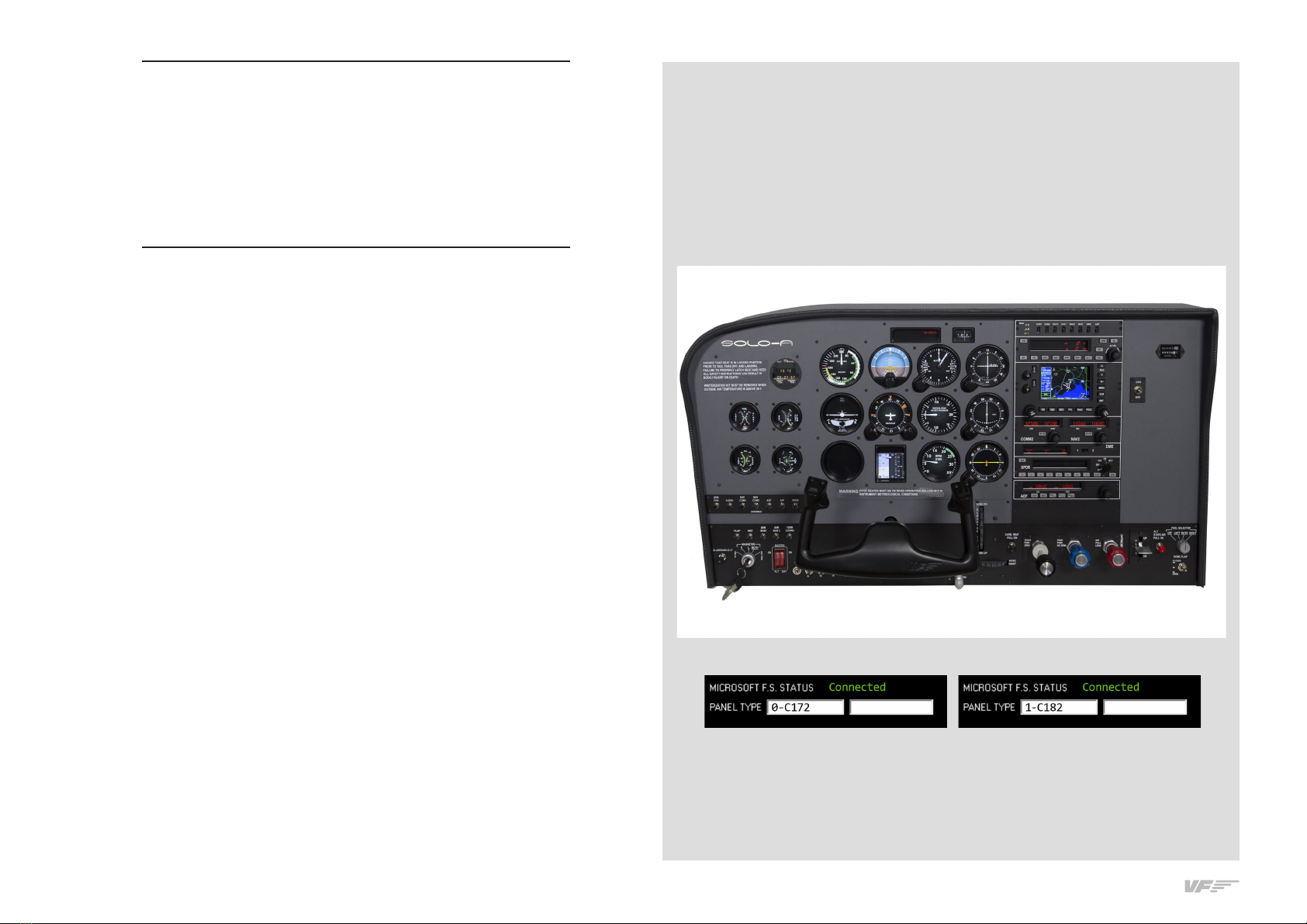
Aircrafts Installation
Copy "VirtualFly_F1Tech_C172S" and "VirtualFly_ F1Tech_182" fol-
ders from the "Memory Stick\Aircrafts" provided with SOLO-A in the
"MFS \SimObjects\Airplanes\ or P3D \SimObjects\Airplanes\".
2.3. YOKO+ AND V3RNIO+ FLIGHT CONTROLS CONIGURATION
YOKO+
Yoko+ calibration on Windows
Calibration on windows is not necessary because the device is calibra-
ted from factory, but you can use the calibration Windows tab to test
the device.
Configuration Using VF-Test&Calibrate
1.Open Prepar3D, go to Controls menu, select YOKO+ from the de-
vices list. Delete all axis and buttons assignments. Close and open
Prepar3D again to make sure that settings have been saved.
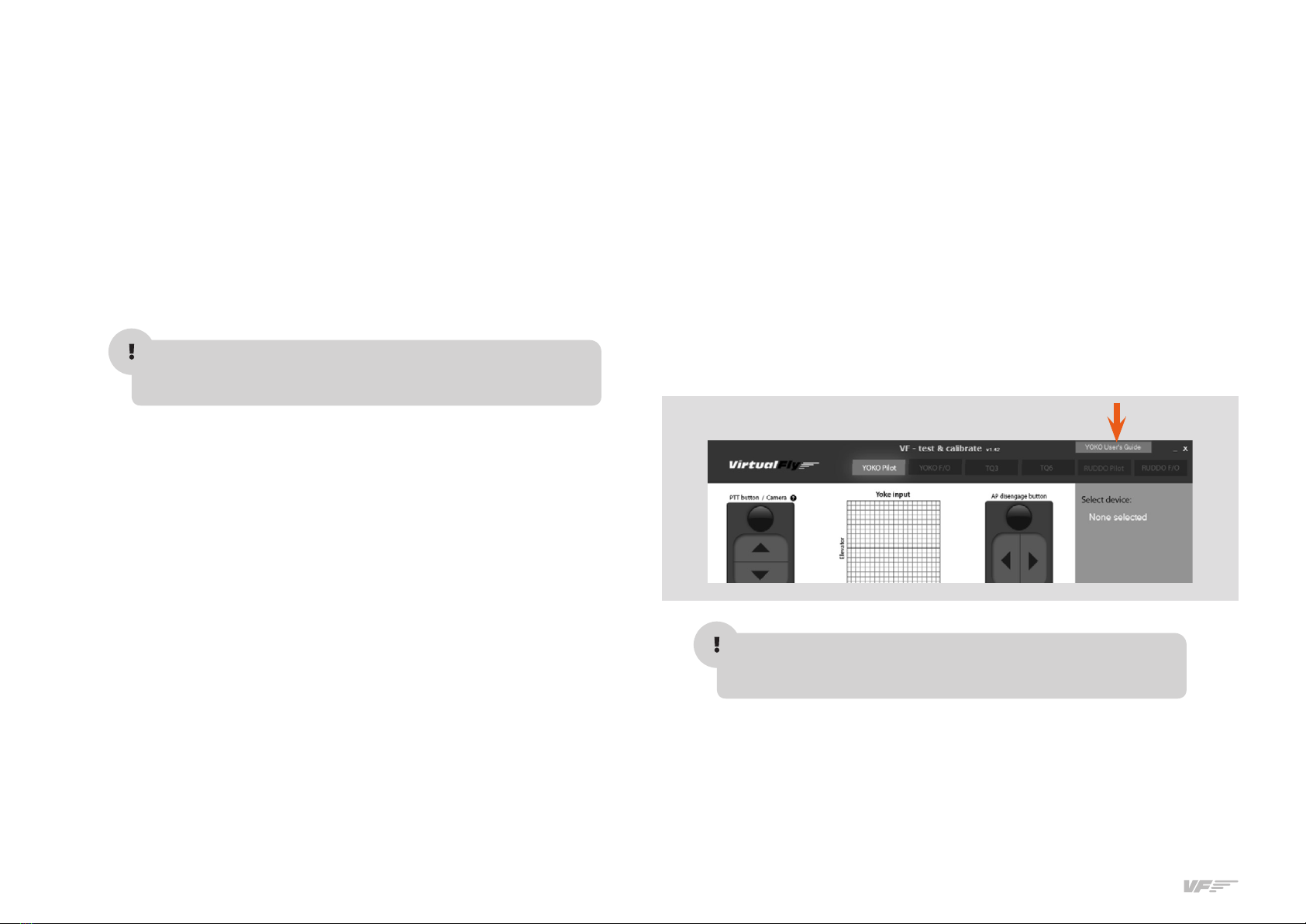
2.Open VFTest&Calibrate-S software, go to YOKO Captain tab and se-
lect the device from the devices list at right side.
3.Now, you can test all the YOKO+ buttons and axes on YOKO Captain
tab. Also you can change the sensitivity though the "actuation curves"
and save changes.
4.VFTest&Calibrate-S has to be running when using YOKO+ because
this software reads the data from the device and send it to Prepar3D
so each time you start Prepar3D, you have to run VFTest&Calibrate-S
as well. You can use Windows Scheduler to start VFTest&Calibrate-S
automatically.
As "VF-Test&Calibrate” Control Panel receive input data from Yoko and
then send it to MFS-Prepar3D, Keep in mind, that VF-Test&Calibrate
Control Panel has to remain ON when you use MFS-Prepar3D.
V3RNIO+
V3rnio+ calibration on Windows +
Calibration on windows is not necessary because the device is calibra-
ted from factory, but you can use the calibration Windows tab to test
the device.

7
2. INSTALLATION - SOLO-A USER'S MANUAL
Configuration Using VF-Test&Calibrate
1.OpenFSX-Prepar3D,gotoControlsmenu,axisassignmentssection
and select TPM VRNIO from the devices list. Delete all axis assign-
ments.CloseandopenFSX-Prepar3Dagaintomakesurethatset-
tings have been saved.
2.OpenVFTest&Calibrate-Ssoftware,gotoTPMV3RNIOtabandse-
lect the device from the devices list at right side.
3.VFTest&Calibrate-ShastoberunningwhenusingTPMV3RNIObe-
cause this software reads the data from the device and send it to
FSX-Prepar3DsoeachtimeyoustartFSX-Prepar3D,youhavetorun
VFTest&Calibrate-Saswell.YoucanuseWindowsSchedulertostart
VFTest&Calibrate-Sautomatically.

83. START UP THE SOLO-A - SOLO-A USER'S MANUAL
The SOLO-A incorporates a mini-computer that is to be connected to
the MFS/PD computer using the previously mentioned Network cable.
It is important to note that in no case should you access or manage
the SOLO-A mini-computer.
• Switch the power switch to ON. (Figure 1)
• Press the push-button to start the "Windows" operating system of the
computer from the SOLO_A. (Figure 1)
• At this time, the "Windows" operating system and all programs found
in the SOLO-A computer will start automatically. It is very important
that SOLO-A is not disconnected or "Windows" stopped while the
programs are loading. Doing so may cause problems with booting
in the future.
The SOLO-A is ready to operate after seconds, you must see the
analog gauges are shown on SOLO-A. (Figure )
• Deactivate the switch BAT on left of the SOLO-A panel.(Figure 3)
• On MFS/P3D Startup the MFS/P3D software.
• To establish the connection between the MFS/P3D computer and the
YOKO just duble click on the “VF-Test&Calibrate.exe” le to execute it.
• To establish the connection between the MFS/P3D computer and the
SOLO-A you must execute the le "VFConnect" from the MFS/P3D
desktop computer (see chapter ).
Attention, do not excute "VFConnect" before MFS/Prepar3D is comple-
tely loaded.
• If you have the Windows FireWall activated, a warning permission to
communicate with networks appears, you must click "Allow Access".
3. START UP
THE SOLO-A
Switch ON Push
FIGURE
FIGURE
FIGURE

9
3. START UP THE SOLO-A - SOLO-A USER'S MANUAL
• Once the connection is established, you should see an image like the
second.
• At the top “This Computer” indicates if the software MFS/P3d is detec-
ted. Only "Connected" will appear when you have initiated MFS/P3d.
• Bellow “Client Connection Status” indicates the connection with the
SOLO-A.
From this moment, we can already appreciate if the SOLO-A and the
MFS/PD computer are communicating. In the SOLO-A annunciator you
will see one of the following (make sure you have the BAT Switch OFF):
• Connected Everything is ready, you can already begin to y.
• Searching There is a communication failure between the MFS/
P3D and the SOLO-A, look at Chapter 8 "Troubleshooting".
If you don't get the connection after reviewing Chapter , please contact
the VirtualFly Technical support: "www.virtual-y.com/en/contact".
DEACTIVATING THE SOLO-A
1. Press the push-button (F) to stop the "Windows" from the SOLO-A
computer, wait for Windows to stop totally.
2. Once "Windows" has stopped, switch the power switch to OFF-0.
In this case the
communication
module is searching
the MFS/Pd
and the SOLO-A In this case, the MFS/PDand SOLO-A are connected
In this case, the MFS/PDand SOLO-A are not connected
In this case the
communication
module is connected
to MFS/Pd
and the SOLO-A
Connected
F

10 4. SELECTION OF PANEL TYPE - SOLO-A USER'S MANUAL
4. SELECTION OF PANEL
TYPE
(ACCORDING THE FSX/P3D PLANE )
The SOLO-A can represent panel types of general aviation aircraft,
Cessna C172SP Skyhawk and Cessna Skylane II RG R182. Most of the
instruments are the same for all both aircraft, whereas other instruments
change according to the plane that will be flown.
The following instruments cahange automatically according to the type
of plane you select:
• Airspeed
• Tachometer – RPM
• Flaps / Trim indicators
• Manifold press / Fuel Press indicator appears only on C-.
Panel type selection
Panel type is selected automaticaly on SOLO-A panel according to the
aircraft selected on MFS or PD.
Note that the only aircrafts models supported by SOLO-A are VirtualFly_
FTech_CS" and "VirtualFly_FTech_" provided in the SOLO-A
Memory Stick.

11
5. RADIOSTACK PANEL - SOLO-A USER'S MANUAL
5. RADIOSTACK PANEL
Peixsoft GA Radio Stack Displays UDP for Virtual-Fly
.. AUTOPILOT (AP) ‘KFC like’
This modied version shows, and allows modication of, values from
the simulator's autopilot. It also provides information about active and
armed modes.
NOTE: The autopilot does nothing by itself; it merely sends to and recei-
ves from FS, the appropriate data, while FS handles the operation. As
a result, Radio Stack may exhibit limited functionality with certain third-
party addon aircraft depending on how complex the autopilot systems
are and how much they deviate from the generic FS systems.
Therefore, although the default aircraft and most addon GA aircraft can
be used successfully with the stack, more complex addon aircraft may
not work at all or demonstrate limited functionality.
Button Definition
. AP Master Switch: Engage/Disengage the autopilot. AP caption lit
on annunciation panel () when ON.
. FD: Flight Director. switch ON or OFF (If installed). FD caption lit on
annunciation panel.
. HDG: Heading mode. This follows the Directional Gyro's or HSI's
"heading bug".
. NAV: Navigation mode (VOR or GPS). Arms the NAV mode to inter-
cept and follow the selected radial on NAV/GPS track.
. APR: Approach mode (LOC or ILS). This arms the APR mode, to inter-
cept the Localizer and the Glide Slope (if available and the NAV radio
is tuned to the ILS frequency).
Note: if HDG mode is active it will be replaced by APR mode when
Localizer is captured and if ALT mode is active it will be replaced by
the Glideslope when captured.
. REV: Back course mode (Rev LOC). It arms the reverse localizer cap-
ture to perform an outbound procedure turn to ILS.
. ALT: Altitude Hold. The altitude maintained is the altitude at the mo-
ment the ALT button is pressed rounded to the nearest hundred.
If the ALT button is pressed with an established climb or descent
rate present, there will be an overshoot, with the airplane returned
positively to the selected altitude. If pressed when ALT hold mode is
engaged, will disengage the mode.
.UP & DN: It is used to change the Vertical Speed (VS) in hundreds.
.ALT Knob: Used to change the selected altitude. The outer knob
changes the altitude in increments of ft and the inner knob in
increments of ft.
.VS: Vertical Speed: When pressed will engage the vertical speed hold
mode. The vertical speed maintained is the vertical speed present at
the moment the VS button is pressed rounded to the nearest hundred.
The rate can be changed using UP or DN buttons. When the VS button
is pressed again, it will disengage the vertical speed mode.
.ARM. This arms the altitude mode. If AP is engaged the plane will
climb or descend to the desired altitude at the selected vertical speed.
Vertical speed can by changed while Alt is engaged by pressing UP
or DN buttons. While altitude is not yet reached, the active mode is
automatically set to VS while ALT is only armed. It will change to active
when the desired altitude is reached.
.Yaw Damper: Switch it ON or OFF (If installed in aircraft being used).

12 5. RADIOSTACK PANEL - SOLO-A USER'S MANUAL
Display
. Roll Active Mode: These can be ROL, HDG, NAV, APR and REV.
• ROL = Wing Leveler active.
• HDG= Heading mode active.
• NAV = NAV1 Radial/GPS track intercepted and following it.
• APR = ILS Localizer captured.
• REV = ILS localizer Back Course captured.
. Roll Armed Mode: These can be NAV, APR, REV and GS. Armed
modes show the ARM caption at its right position.
.Altitude selected: This is the desired or maintained altitude. It can be
changed using the rotary knobs ().
- Vertical Speed selected: This is the selected Vertical Speed.
.Alert annunciator: This label appears when the aircraft altitude is
between ft and ft of the desired altitude. It always occurs,
even when AP is o or altitude hold is not active.
.Pitch Active Mode: this can be VS, ALT and GS.
• VS: Vertical Speed Mode.
• ALT: Altitude is reached and hold.
• GS: ILS Glide Slope is captured.
- Pitch Armed Mode: This can be ALT. Armed modes show an ARM
caption to the right.
.Annunciator: This has two columns, left for AP options and right for
A/T options.
- Left column show the next options:
AP: Master AP switch is engaged.
YD: Yaw Damper is On.
FD: Flight Director is On.
- Right column show:
AT: Autothrottle is On.
TOGA: TOGA is On.
.. COMMUNICATIONS AND NAVIGATION
COM & NAV equipment is integrated in the one device.
.. DISTANCE METERING EQUIPMENT (DME)
This DME allows the user to choose between DME or , linked to NAV
or NAV respectively. Due to FS limitations, it always works in remote
mode (cannot work with an independent frequency).
If no signal from DME is received dashes appears on the screen.
Frecuency
in use
Frecuency
in use
Frecuency
transfer
Frecuency
transfer
Distance
meter (NM)
(Nautical Miles)
Speed to the
station (KT)
(Knots)
Time to the
station (MIN)
(Minutes)
Source
Selector
STBY Frecuency
selector
STBY Frecuency
selector
COMMUNICATIONS NAVIGATION
Frecuency in
Stand by
Frecuency in
Stand by

13
5. RADIOSTACK PANEL - SOLO-A USER'S MANUAL
.. AUTOMATIC DIRECTION FINDER (ADF)
This is % functional; the ADF and BFO buttons are working but per-
form no actions. (FS does not allow the user to move the needle to 90º
as would be usual in ANT mode).
Frequency Mode (Frq)
In its main mode, it shows two frequencies: Used and Standby.
Flight Time Mode (FLT)
An internal chrono is started when the device is activated, and it counts
both Hours and Minutes. It always works (in any mode) while the device
is On.
Chrono Mode - Elapsed Time (ET)
The ET mode allows a chrono with Minutes and Seconds (until :).
The chrono begins to count when you press SET/RST push button (also
when other mode is selected) and returns to start every time SET/RST is
pressed. Can not be stopped, always is reset to and begins to count
automatically.
Countdown Mode (ET blinking).
A countdown of a maximum of minutes, seconds is allowed. To
enter countdown mode, the SET/RST pushbutton must be pressed and
maintained (with the mouse) for seconds or longer, or until ET starts
to blink.
Subsequently, you should select the initial time with the rotatory knobs,
the big one to select the minutes and the small for the seconds, and
press the SET/RST pushbutton to start the countdown.
When the time reaches the mode reverts to normal ET Mode and
begins to count up, but to advise you of the time blinks for seconds.
The example picture shows minutes in FLT mode.
Change
between
ADF & ANT
mode
In Use
Frequency
Enables
BFO
modulation
FQR
Mode
Enables FRQ
mode and Enables
BFO modulation
frequency transfer
Stand By
Frequency
FLT Mode indication (HH:MM)
ET Mode indication (MM:SS)
ET Countdown (MM:SS) ET Blinking
FLT and ET modes switch
Starts and reset the chrono,
and enable the countdown mode
Pressed > seconds enables the
countdown mode (ET blinking).
Units
selector
Seconds
selector
Hundreds and
thousands
selector
Minutes
selector

14 5. RADIOSTACK PANEL - SOLO-A USER'S MANUAL
.. TRANSPONDER (XPDR)
Sequential code full functional XPDR including the ight level in ALT
mode.
Mode selector
This can be changed with the rotatory knob (OFF, SBY, TST, ON, ALT).
The selected mode appears lit on the screen (SBY, ON, ALT). The TST
mode lights all indicators.
Note: The SBY mode is only for instruction purposes as FS treats it as
always-ON.
IDT: Simulated Ident action showing the “R” caption for seconds.
0 a 7: Direct entry of XPDR’s code. Code is inserted sequentially; When
inputting values, a dash appears in the digit that waits to be changed. If
the code is not completed in a reasonable time (more than seconds
from the last insertion) the code reverts to the last used code.
CLR: Clears the last digit inserted, waiting for a new entry, if it is pressed
several times it going back until arriving at the beginning.
VFR: Puts automatically the VFR code predened in the General
Conguration screen.
Flight Level,
available in
ALT mode
Ident Actual Mode
indications
XPDR
Code
Mode
Selector
Automatic
VFR code
Clear the last
number inserted
Direct insertion keys (..)

15
6. GPS GNS-530 - SOLO-A USER'S MANUAL
6. GPS GNS-530
The SOLO-A includes the GPS GNS- simulator. This GPS is not the
original from Garmin, both the hardware part and software part are de-
signed to simulate the real.
The software part is made by FLIGHT AVIATION TECHNOLOGIES, on
http://www.ight1tech.com/ you can nd all the information of the deve-
loper.
To operate this replica of GNS- we added on the memory stick the
manual from a reliable source “GNS530_pilotsGuide”.
This GNS-530 Simulator is modeled after the GNS 530W and features
• A WAAS-certied GPS.
• A multi-channel capacity VHF comm radio.
• A multi-channel ILS/VOR with localizer and glideslope receivers.
• Built-in WAAS navigation capabilities to y LPV "glideslope" ap-
proaches without reference to ground-based navaids of any kind
(providing vertical and lateral approach guidance into thousands of
U.S. airports previously inaccessible in IFR conditions).
• Updateable, built-in terrain and navigation databases that contain
location reference for all airports, VORs, NDBs, Intersections, Flight
Service Stations, published approaches, SIDs/STARs, Special Use
Airspace and geopolitical boundaries.
• A detailed basemap that shows airports, cities, highways, railroads,
rivers, lakes, coastlines and more.
• Terrain proximity warnings and Terrain Awareness and Warning
System (TAWS) alerting.
• Integration with standard autopilots that accept roll-steering com-
mands to automatically y your aircraft through holding patterns, pro-
cedure turns and other position-critical IFR ight procedures.
In the following pages, there is a basic explanation of the main buttons
and indicators.
Keep in Mind that the VOLUME commands are not working in this si-
mulator.
.. KEY AND KNOB FUNTIONS
The GNS is designed to make operation as simple as possible. The
key knob descriptions (Figure -) provide a general overview of the
primary function(s) for each key knob.
Experiment with the unit and refer to the reference sections for more
information. Data is entered using the large and small knobs. Experiment
with them to become ecient at entering data. This greatly reduces the
amount of time spent operating the GNS 530 in ight.

16 6. GPS GNS-530 - SOLO-A USER'S MANUAL

17
6. GPS GNS-530 - SOLO-A USER'S MANUAL

18 7. MULTIPLE SOLOFLIGHTPANEL OR MULTIPLE MFS/P3D COMPUTER IN THE SAME NETWORK - SOLO-A USER'S MANUAL
7. MULTIPLE SOLO-
FLIGHTPANEL OR
MULTIPLE MFS/P3D
COMPUTER IN THE
SAME NETWORK
If you connect more than one SOLO-A to the same network, you should
be aware that to use them simultaneously you should have more than
one computers using MFS/PD connected to the same network and in-
dicate the right MFS/PD computer to each SOLO-A, as detailed below.
• Connecting a PC to one of the SOLO-A, just can be turned on the
SOLO-A which you want to connect. When you will execute SOLO-A_
Connect, it will detect the active SOLO-A and will connect.
• Once a PC and SOLO-A are connected, they will remain connected
during the session. At this point, if a second SOLO-A is turned on and
a second PC runs SOLO-A_Connect, this just will detect the SOLO-A
which is free and will connect.
• You should take into account that never a connection between a spe-
cic SOLO-A and PC is saved, Connections are made automatically
when SOLO-A_Connect starts and it nd a SOLO-A which is available
(free of connection to a PC ).
• If you want to prevent a SOLO-A to connect to another PC, or make
sure that a SOLO-A will connect to the same PC, connect them di-
rectly without going by the LAN.

19
8. TROUBLESHOOTING - SOLO-A USER'S MANUAL
.. ANOMALY: THE INDICATOR PANEL DISPLAYS “MFS Status: Searching…”
8. TROUBLESHOOTING
POSSIBLE
CAUSE 1 Network cable nº is not connected.
SOLUTION Check connection of network cable nº between SOLO-A and MFS/
Pd PC
POSSIBLE
CAUSE 2 MFS/PD is not running
SOLUTION Execute MFS/PD
POSSIBLE
CAUSE 3 FSUIPC is not installed
SOLUTION Install the FSUIPC. See chapter
POSSIBLE
CAUSE 4 “VFConnect.exe” is not executed
SOLUTION Execute “VFConnect.exe” on the MFS/Pd PC. Is better to execute
“VFConnect.exe” once MFS/PD is loaded
POSSIBLE
CAUSE 5 Windows rewall does not allow communication to SOLO-A
SOLUTION You will have to add an exception manually to allow communication. For
that, follow the steps below:
. Press combo key Windows + R
2. Write “rewall.cpl” on the window that has appeared.
3. A Windows rewall window should appear.
. Depending on your windows version:
a. Windows XP: On the exceptions tab, there is a list where you should
nd VFConnect, check the check box to allow that it connects. If
VFConnect is not on the list, press “Add a program” button and
explore to the desktop and select “VFConnect.exe” le.
b. Windows Vista: On the window that has appeared, on the left side
press “Allow a program through the Windows Firewall”. Search
VFConnect on the list and make sure that the check box on the
“Public” column is checked. If VFConnect is not on the list, press
“Add a program” button and explore to the desktop and select
“VFConnect.exe” le from the desktop.
c. Windows /: On the window that has appeared, on the left side
press “Allow a program or a feature through the Windows Firewall”.
Search VFConnect on the list and make sure that the check box
on the “Public” column is checked. If VFConnect is not on the list,
press “Add a program” button and explore to the desktop and select
“VFConnect.exe” le from the desktop.
POSSIBLE
CAUSE 6 PC has more than one network card
SOLUTION If you are using a PC which has more than one network card, try one of
these options:
. If you are trying to use one network card to connect to your router and
another one to connect directly to SOLO-A and it does not work, try
connecting SOLO-A directly to your router instead of connecting to the
pc. This way, connection will be established through the network LAN.
. If you have connected SOLO-A directly to your PC and your PC has
the other network sockets free, try connecting SOLO-A to the PC using
another network card.
POSSIBLE
CAUSE 7 Network problems
SOLUTION If you have connected your PC and SOLO-A directly (without router), at
the beginning you will have to wait some time, even more than a minute,
because Windows set IP addresses automatically.
If after a few minutes the connection is not established, try the following:
Make sure that IP conguration is in DHCP, for that:
. Press Windows + R key and on the window that will appear, write “ncpa.
cpl” and press enter.

20 8. TROUBLESHOOTING - SOLO-A USER'S MANUAL
. A window will appear with the various network connections. If you have
more than one, press over which is active (icon has color), by the right
button of the mouse → “properties”. A window like this will appear:
. Search on the list “Internet protocol version (TCP/IPv)”, select it
and press on “properties”. A window like this will appear.
. Make sure that the options “Obtain an IP address automatically” and
“Obtain DNS server address automatically” are chosen.
. If still there is no connection between SOLO-A and your PC after the
process, try rebooting SOLO-A and your PC.
POSSIBLE
CAUSE 8 Network Discovery disabled
SOLUTION Check that in your current network profile (Public / Home or Work )
Network discovery option is turned on.
For that, go to: "Control Panel\All Control Panel Items\Network and
Sharing Center\Advanced sharing settings" and turn Discovery Network
option on for all profiles available.
8.2. ANOMALY: CONNECTION GOES DOWN, IS INTERMITTENT OR INDICATORS
MOVES SHARPLY
POSSIBLE
CAUSE 1 Connection trough Wifi
SOLUTION If you are using a PC which is connected to your network by Wifi, even
SOLO-A is connected by cable, It is possible that due to interference,
noise or other electromagnetic signal, connection will not be constant. It
is so recommendable using always a network cable to connect SOLO-A
to the router and your PC to the router also, or alternatively a direct cable
between your PC and SOLO-A to enjoy completely of your SOLO-A.
POSSIBLE
CAUSE 2
Your MFS/PD PC is executing another program on the background that
uses all the bandwidth of the network card.
SOLUTION To guarantee the best perform of the connection, it is recommendable
during the session, to close programs which make an intensive use of
the network connection or computer processor.
Table of contents
Other Aircatglobal Switch manuals
Popular Switch manuals by other brands

Action Star
Action Star PK-2PA0-A-EL user guide

ZyXEL Communications
ZyXEL Communications Dimension GS-3012F user guide

Hypertherm
Hypertherm powermax65 Field Service Bulletin

Intel
Intel Express 10/100 Stackable Hub Ethernet Module user guide

Inficon
Inficon VSC150 operating manual

Halemeier
Halemeier Magic Switch 230V installation instructions

Extreme Networks
Extreme Networks 3626 Quick install guide

Pepperl+Fuchs
Pepperl+Fuchs PROFINET IO Power Hub manual

Manhattan
Manhattan 161169 Specifications

Eaton
Eaton Cutler-Hammer ATC-300 O & M Manual

ATEN
ATEN ALTUSEN KW1000 user manual

Rose electronics
Rose electronics QuadraVista Quick installation guide