Aircraft AIRBOY 186 OF E User manual

AIRBOY 186 OF E
Operating Instructions
AIRBOY 186 OF E
AIRBOY
Mobile Compressor
AIRBOY 206 OF E
AIRBOY 206 OF E

2AIRBOY | Version 1.07
Imprint
Product identification
Compressor Item number:
AIRBOY 186 OF E 2001230
AIRBOY 206 OF E 2001235
Manufacturer
AIRCRAFT
Kompressorenbau und Maschinenhandel GmbH
Gewerbestraße Ost 6
A-4921 Hohenzell
Phone: 0043 (0) 7752 70 929 - 0
Fax: 0043 (0) 7752 70 929 - 99
E-Mail: [email protected]
Internet: www.aircraft.at
Sales Germany
AIRCRAFT - Stürmer Maschinen GmbH
Dr.-Robert-Pfleger-Straße 26
D-96103 Hallstadt/Bamberg
Fax: 0049 (0) 951 - 96555-55
E-Mail: [email protected]
Internet: www.aircraft-kompressoren.com
Indications regarding the operating instructions
Original instructions
Edition: 25.09.2019
Version: 1.07
Language: english
Author: KP/FL
Indications regarding the operating instructions
Copyright © 2019 AIRCRAFT Kompressorenbau und
Maschinenhandel GmbH, Hohenzell, Austria.
The contents of these operating instructions is the sole
property of the company AIRCRAFT Kompressorenbau
und Maschinenhandel GmbH.
Passing on as well as copying of this document, the use
and distribution of its contet are prohibited if not expli-
citly permitted. Contraventions are liable to compensa-
tion.
Subject to technical modifications and error.
Content
1 Introduction .............................................................3
1.1 Copyright............................................................ 3
1.2 Customer service................................................ 3
1.3 Limitation of liability ............................................ 3
2 Safety........................................................................3
2.1 Symbol explanations .......................................... 4
2.2 Operator responsibility ....................................... 4
2.3 Operating staff qualification ............................... 5
2.4 Personal protective equipment........................... 5
2.5 General safety instructions................................. 5
2.6 Verification of operational safety ........................ 6
2.7 Safety marking on the compressor..................... 7
2.8 Safety devices .................................................... 7
3 Intended use ............................................................7
3.1 Foreseeable misuse ........................................... 7
3.2 Residual risks ..................................................... 8
4 Technical data .........................................................8
4.1 Type plate........................................................... 8
5 Transport, packaging, storage...............................8
5.1 Delivery and Transport ....................................... 8
5.2 Packaging........................................................... 8
5.3 Storage ............................................................... 8
6 Description of the device........................................9
7 Operation .................................................................9
7.1 Assembly and installation................................. 10
7.2 Switch on .......................................................... 10
7.3 Adjustment of working pressure....................... 11
7.4 Switch off .......................................................... 11
8 Maintenance, care and servicing/
repair ......................................................................11
8.1 Cleaning ........................................................... 11
8.2 Maintenance..................................................... 12
8.3 Function test of the safety valve ....................... 13
8.4 Service.............................................................. 13
8.5
Information about the technical customer service
... 13
8.6 Troubleshooting................................................ 13
9 Disposal, recycling of used devices....................14
9.1 Decommissioning............................................. 14
9.2 Disposal of lubricants....................................... 14
10 Spare parts...........................................................14
10.1 Ordering spare parts...................................... 14
10.2 Spare parts drawing....................................... 15
11 EC-Declaration of Conformity ............................17

Introduction
AIRBOY | Version 1.07 3
1Introduction
You have made a good choice by purchasing the com-
pressor made by AIRCRAFT.
Please thoroughly read the operating instructions befor com-
missioning.
It informs you about the proper commissioning, the in-
tended use as well as the safe and efficient operation
and maintenance of your compressor.
The operating instructions are part of the compressor.
Always keep it at the place of use of the compressor.
Furthermore, the local accident prevention regulations
and the general safety notes are applicable for the field
of application of the compressor.
The illustrations in these operating instructions serve the
general comprehension and may deviate from the ac-
tual type.
1.1 Copyright
The contents of these instructions are copyright. Their
application is admissible in the frame of the compressor
utilisation. An application beyond the decribe applica-
tion is not allowed without written approval of the manu-
facturer.
For the protection of our products, we shall register tra-
demark, patent an design rights, as this is possible in in-
dividual cases. We strongly oppose any infringement of
our intellectual property.
1.2 Customer service
Please contact your dealer if you have questions on your
compressor of if you need technical advice. They will
help you with specialist information an expert advice.
Austria:
AIRCRAFT Kompressorenbau und Maschinenhandel
GmbH
Gewerbestraße Ost 6
A-4921 Hohenzell
Phone: 0043 (0) 7752 70 929-0
Fax: 0043 (0) 7752 70 929-99
E-Mail: [email protected]
Internet: www.aircraft.at
Germany:
Stürmer Maschinen GmbH
Dr.-Robert-Pfleger-Str. 26
D-96103 Hallstadt
Repair service:
Fax: 0049 (0) 951 96555-111
E-Mail: [email protected]
Spare part orders:
Fax: 0049 (0) 951 96555-119
E-Mail: ersatzteile@stuermer-maschinen.de
We are always interested in valuable experience and
knowledge gained from using the application, which
then could be shared and be valuable to develop our
products even further.
1.3 Limitation of liability
All information and notes in these operating instructions
were summarised taking the applicable standards and
rules, the state-of-the-art and our long-term knowledge
and experiences into consideration.
In the following cases the manufacturer is not liable for
damages:
- Non-observance of the operating instructions,
- Inappropriate use,
- Use of untrained staff,
- Unauthorised modifications,
- Technical chances,
- Use not allowed spare parts
The actual scope of delivery may deviate from the ex-
planations and presentations described here in case of
special models, when using additional ordering options
or due to latest technical modifications.
The obligations agreed in the delivery contract, the ge-
neral terms and conditions as well as the delilvery con-
ditions of the manufacturer and the legal regulations at
the time of the conclusion of the contract are applicable.
2 Safety
This paragraph will give you an overview of all important
safety packages for the protection of the people using it
well as for a safe and undisturbed operation. Other task-
based safety notes are included in the individual chap-
ters.

4AIRBOY | Version 1.07
Safety
2.1 Symbol explanations
Safety instructions
The safety notes in these operating instructions are
highlighted by symbols. The safety notes are introduced
by signal words which exoress the concern of the risk.
Tips and recommendations
It is necessary to observe the safety notes written in
these operating instructions in order to reduce the risk of
personal injuries and damages to property.
2.2 Operator responsibility
Operator
Operators are defined as the persons who operate the
machine for commercial or profit-based purposes or
provide the machine to third parties for use or applica-
tion and bear the legal product responsibility in terms of
the protection of users, staff or third parties during oper-
ation.
Obligations of the operator:
If the machine is used for commercial purposes, opera-
tors are subject to the legal stipulations in terms of occu-
pational safety. For this reason, the safety instructions in
these operating instructions as well as the safety, acci-
dent prevention and environmental protection regula-
tions valid at the installation location must be complied
with. In this process, the following shall apply in particu-
lar:
- Operators shall obtain information about valid oc-
cupational safety regulations and determine addi-
tional hazards as part of a risk assessment which
result from the specific operating conditions at the
machine's installation location. Said risk assess-
ment shall be reflected in operating instructions for
machine operation.
- During the entire machine operating time opera-
tors must check whether the operating instructions
they created meet current standards and adapt
the operating instructions where necessary.
- Operators shall clearly manage and specify the re-
sponsibilities for installation, operation, trouble-
shooting, maintenance and cleaning.
- Operators must make sure that all persons han-
dling the machine have read and understood
these operating instructions. Operators must also
regularly train staff and notify of the hazards.
- Operators shall provide staff with the required pro-
tective equipment and wearing the required pro-
tective equipment shall be mandatory.
Operators shall also be responsible for maintaining the
machine in a technically perfect condition. For this rea-
son, the following shall apply:
- Operators shall make sure that the maintenance
intervals described in these operating instructions
are complied with.
- Operators shall regularly check that the safety
equipment is fully functional and complete.
DANGER!
This combination of symbol and signal words indica-
tes an imminently dangerous situation which may
lead to death or severe injuries if they are not avoi-
ded.
WARNING!
This combination of symbol and signal words indica-
tes a possibly dangerous situation which may lead
to death or severe injuries if they are not avoided.
CAUTION!
This combination of symbol and signal words indi-
cates a possibly dangerous situation which may
lead to minor or light injuries if they are not avoided.
ATTENTION!
This combination of symbol and signal words indi-
cates a possibly dangerous situation which may
lead to property and environmental damages if they
are not avoided.
NOTE!
This combination of symbol and signal words indi-
cates a possibly dangerous situation which may
lead to property and environmental damages if they
are not avoided.
Tips and recommendations
This symbol highlights useful tips and recommenda-
tions as well as information for an efficient and trou-
ble-free operation.

Safety
AIRBOY | Version 1.07 5
2.3 Operating staff qualification
Qualifications
The different tasks described in these operating instruc-
tions require different levels of skills in terms of the qual-
ifications of operating staff working with the machine.
Exclusively persons of whom it can be expected that they
reliably complete assigned tasks shall be authorised to
carry out any tasks. Persons whose reactions have been
impaired shall not be authorized, e.g. drug users, users
under the influence of alcohol or medication.
This manual identifies the qualifications of the persons li-
sted below for the different tasks:
Operator
The operator has been instructed in a briefing by the
operator about the tasks assigned to him and possible
dangers of improper behavior. The operator may only
carry out tasks that go beyond normal operation if this is
specified in this operating manual and the operator has
expressly entrusted this to him.
Qualified electrician:
Due to the electrician's specialised training, know-how,
experience and knowledge of pertinent standards and
regulations the electrician is in a position to work on the
electrical systems, and autonomously identify and avoid
potential hazards.
Specialist staff:
As a result of specialist training, expertise, experience
and skills in terms of the relevant standards and regula-
tions, specialist staff is able to complete the tasks they
are entrusted with and independently identify hazards
and avert risks.
Manufacturer:
Certain work must be carried out by manufacturer spe-
cialist staff only. Other staff is not permitted to carry out
this work. Contact our customer service to have the work
carried out.
2.4 Personal protective equipment
Personal protective equipment is intended to protect the
health and safety of persons at work. Staff must wear the
personal protective equipment indicated in individual
sections of these operating instructions when carrying
out the different tasks on the machine.
The personal protective equipment is described in the
following section:
2.5 General safety instructions
- Observe the guidelines and accident prevention
regulations of the employers' liability insurance as-
sociation for the handling of compressors and
pneumatic tools
- The compressor must not be operated in rainy or
humid or wet conditions.
WARNING!
Risk from inadequately qualified persons!
Inadequately qualified persons are unable to assess
the risks when handling the machine, thus putting
themselves and others at risk of severe injuries.
- All work must be carried out by qualified persons
only.
- Keep inadequately qualified persons and children
away from the work area.
Hearing protection
Hearing protection protects the ears against hear-
ing damage caused by noise.
Eye protection
Protective glasses protect the eyes against pro-
jected parts and splashes of liquid.
Respiratory protection
Respiratory protection serves to protect the respira-
tory tract and lungs against absorbing dust parti-
cles.
Protective gloves
Protective gloves protect the hands from compo-
nents with sharp objects as well as friction, abrasion,
and deep-cut injuries.
Safety shoes
Safety shoes protect feet from pinching, falling parts
and slipping on slippery surfaces.
Protective clothing
Protective work clothing means tight-fitting clothing
with low tear resistance.

6AIRBOY | Version 1.07
Safety
2.6 Verification of operational safety
The pressure tank of the compressor is submitted to inspec-
tion. The manufacturer submitted the pressure tank to an in-
spection according to the EC Directive 2014/29 EG in conjunc-
tion with the EC type examination according to article 10 as
well as according to EN286-1. A copy of this type examination
certification and/or declaration of conformity is included in the
scope of delivery of every compressor.
The operating company must have re-inspected the individual
components to be inspected by an expert or by a „qualified
person“ in the perscribed intervals. The operating regulations
for this may differ in the individual EC countries.
Regulations for compressed air tanks in Germany
Inspection periods
The given inspeciton periods are maximum values. They
should be verified by the risk assessment/valuation of em-
ployer of the operating company. No delays are admissible for
this. It is only possible to shorten the period.
The product of pressure and volume depends on the inspec-
tion periods. For this, the maximum admissible pressure (PS)
must be multiplied with the pressure tank volume (V).
Example:
Pressure tank= 50l ; max. zulässiger Druck= 10 bar
50 l x 10 bar = 500
*The employer must communicate the relevant inspection peri-
ods to the responsible authority within 6 month after commis-
sioning the installation(par. 15 BetrSichV).
**External tests can be omitted: a) for pressure tanks accor-
ding to point 2.2 (letter a)BetrSichV, unless they are fire-hea-
ted, heated exhaust gas or electrically heated, and
b) in the case of simple pressure tanks according to BetrSichV
point 2.2 letter d. The deadline of the strength test may be ex-
tended to 15 years If it is shown in the external or internal test
that the machine can be safely operated. The confirmation
must be shown in the documentation of the risk assessment.
Table according to BetrSichV (State: 29.03.2017).
Regulations for compressed air tanks in Austria
Pressure devices as of 0,5 bar are submitted to the „Vessel
Law“ pressure devices monitoring directive (DGÜW-V) in Aus-
tria.
This directive makes a differentiation between low hazard po-
tential (NGP) and high hazard potential (HGP) .
NGP: Overall compressed air product (pxV) below 3000 litres
HGP: Overall compressed air product (pxV) above 3000 litres
NGP (Low risk potential)
For the devices that fall into the NGP, the operator has no obli-
gation to inform boiler test centers. If a customer buys a device
with NGP, he / she does NOT have to register this for the first in-
spection by a boiler testing center (TÜV Austria Services
GmbH).
HGP (low hazard potential)
The operating company is not obligated to inform vessel in-
spection authorities for devices classified as NGP.
For devices that fall into the HGP you need a first operation test
from a boiler testing center (TÜV Austria Services GmbH).
With the declaration of conformity and the operating instructi-
ons, the tank must be reported to the boiler testing center.
TÜV AUSTRIA SERVICES GMBH
Lunzerstraße 89
4030 Linz/Österreich
http://www.tuv.at
They carry out the service test. und stellen,if everything is ok, fill
in a book.The container is then subjected to periodic inspecti-
ons (eg test level 4, minor damage: every 2 years external ex-
amination, every 6 years an internal examination and every 12
years main examination)
CAUTION! RISK OF INJURY
- Never direct compressed air to persons or animals.
- Grab the end of the compressed air hose with your
hand before opening the quick coupling in order to
prevent the tool from flying off by pressure.
- Allow the compressor to cool down prior to main-
tenance work.
Check Inspection periods Inspection organisa-
tion
Prior to commis-
sioning/ positio-
ning
PS x V </=200 Qualified person
with type exami-
nation certificate
PS x V </=1000
Qualified person
PS x V >/=200 Approved inspec-
tion agency
Exterior inspec-
tion
**
Once a year/
every 2 years
PS x V </= 1000
Qualified person
Interior inspec-
tion
**
Once every 5
years for PS x V
</=1000
Qualified person
*Every 5 years
PS x V >/=1000
Approced inspec-
tion agency
Strength test** Once every 10
years
PS x V </=1000
Qualified person
*Once every 10
years
PS x V >/=1000
Approved inspec-
tion agency
Check Inspection periods Inspection organisa-
tion

Intended use
AIRBOY | Version 1.07 7
2.7
Safety marking on the compressor
The following safety symbols are attached to the com-
pressor:
Fig. 1: Safety symbols on the compressor
Damaged or missing safety symbols on the compressor
may lead to errors and material damages. The safety
symbols applied to the compressor must not be re-
moved.
Please observe the following points:
The instructions of the safety symbols at the compressor
must be observed under all circumstances. Attach new
labels immediately if the safety symbols fade out or be-
come damaged during the lifetime of the compressor.
Damaged safety symbols must be replaced immedi-
ately.
The compressor must be put out of operation from the mo-
ment when the labels are unable to be recognized and un-
derstood at first glance, until new labels are attached.
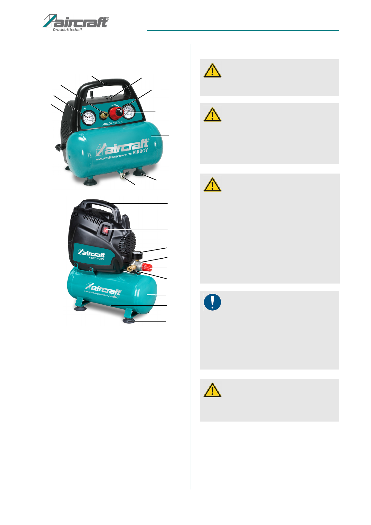
2.8 Safety devices
Safety valve
The safety valve is locatedat the top of the housing (AIR-
BOY 186 OF E) or on the fitting (AIRBOY 206 OF E).
When the safety value is reached, the safety valve
opens and lets off air. After triggering the safety valve,
the operator must turn off the compressor and request
control by the maintenance personnel.
Motor protection
The compressor is equipped with a motor protection that
automatically shuts off the compressor when overloaded.
After a sufficient cooling phase, the compressor can be
restarted.
3 Intended use
The compressor serves for the operation of pneumatic
tools and pneumatic control systems and installations
provided for this purpose. It was developed to aspire
clean, dust-free and unloaded ambient air, and to com-
press it. The ambient air must not be loaded with ag-
gressive or combustible additions. The compressor may
only be operated in closed rooms with sufficient ventila-
tion. It is protected against overheating with a motor pro-
tection switch. The motor protection switch triggers au-
tomatically when the safety limit values are reached.
However we recommend not to load the compressor
above 50% of its capacity, and not to have it run in con-
tinuous operation for more than 15 minutes.
Furthermore, many accessories can be connected to
the compressor beyond pneumatic tools, which can be
used for blowing, washing and spray-painting. We
kindly ask you to consult the corresponding operating
manuals in order to ensure the correct usage of these
accessories.
The compressor must not be used in the food and
health area, e. g. for filling breathing gas cylinders.
the compressor and the connected pneumatic tools
may only be operated by an instructed person. Children
and adolescents must not operate the compressor and
connected pneumatic tools.
The proper use also includes observing all indications in
these operating instructions. Any use beyond the proper
use or any other use is regarded as misuse
.
Bei dem Kompressor handelt es sich um durch einen
The compressor is a piston compressors driven by an
electric motor and connected to a compressed air stor-
age tank; it is intended to be sold and operated in the
EU region as well as in the geographical region of Eu-
rope.
3.1 Foreseeable misuse
If the intended use is observed, any reasonably foresee-
able misuse which could lead to hazardous situations
with personal damage is impossible with the Compressor.
DANGER!
The piston compressor, as produced in series, is not
explosion-protected and must not be used in areas
with explosion hazards!
WARNING!
Danger in case of misuse!
A misuse of the compressor can result in dangerous
situations.
- Only operate the compressor in the power range
given in the technical specifications.
- Never bypass or override the safety devices.
- Only operate the compressor in a technically flaw-
less status.
NOTE !
If the compressors are not used as intended, or if the
safety directives or operating instructions are ignored,
or if the compressors are modified without authorisa-
tion, the liability of the manufacturer for any damages to
persons or objects resulting here of is excluded and
the claim under guarantee is becoming null and void!!

8AIRBOY | Version 1.07
Technical data
3.2 Residual risks
Even if all safety regulations are observed there will remain
a residual risk in the operation of
the compressor
, descri-
bed in the following. All persons working with
the com-
pressor
must know these residual risks and follow the in-
structions which prevent any accidents or damages
caused by these residual risks. During set-up and adjust-
ment works it may become necessary to remove safety de-
vices installed by the customer. This causes different resi-
dual risks and hazard potentials each operator must be
aware of.
4 Technical data
*Sound power level according to DIN EN ISO 3744 (RL 2000/14/EG)
4.1 Type plate
The type plate (Abb.2) shows the following information:
Fig. 2: Type plate
Designation of model
Power of engine
connection data
Years of construction
Item number
Serial number
5 Transport, packaging, storage
5.1 Delivery and Transport
Delivery
Check the compressor for any visible transportation
damages after delivery. If the compressor shows any
damages, immediately inform the carrier or the distribu-
tor.
Check whether the compressor is complete and
whether all parts included in the scope of delivery are
present.
Transport
The compressor may only be transported with the en-
gine switched off and disconnected from the mains. The
container must not be under pressure during transport.
5.2 Packaging
Keep the packaging for a possible move, but at least
during the warranty period.
All used packaging materials and packaging aids the
compressor are recyclable and generally need to be
transported to the material recycling.
Crush the packaging material made of cardboard and
supply it to the waste paper collection.
The films are made of polyethylene (PE) and the uphol-
stery parts are made of polystyrene (PS). These materi-
als have to be delivered to a recycling station of the re-
sponsible dumping company.
5.3 Storage
The Compressor must be stored thoroughly cleaned in a
dry, clean and frost-free environment.
Do not store or transport the compressor outside or in a
moist environment.
AIRBOY 186 OF E AIRBOY 206 OF E
Maximum volume
flow
180 l/min 180 l/min
Max. pressure
8 bar 8 bar
Tank capacity
6 Liters 6 Liters
Cylinders/levels
1 /1 1 /1
Number of revolu-
tions
3400 rpm 3400 rpm
Engine power
1,1 kW / 230 V 1,1 kW / 230 V
Type of Protection
IP 20 IP 20
Duty cycle
S3-25 S3-25
Weight
9,2 kg 9,0 kg
Dimension(Lx-
BxH) [mm]
315x355x370 385x170x465
Sound power level
L
W
A *
97 dB(A) 97 dB(A)

Description of the device
AIRBOY | Version 1.07 9
6Description of the device
Fig. 3: AIRBOY 186 OF E (above) and AIRBOY 206 OF E (below)
1 Safety valve
2 Pressure regulator for removal pressure
3 Pressure gauge container pressure
4 Compressed air tank
5 Suction cup
6 Tank drainage (hidden)
7 Pressure gauge extraction pressure
8 Compressed air extraction clutch
9 Handle
10 On / OFF Switch
7 Operation
1
2
3
4
5
6
7
8
9
10
9
10
3
2
5
6
1
8
4
ATTENTION!
The compressor may only be operated in an admissi-
ble temperature range of +5°C to +40°C!
ATTENTION!
Do not overload the compressor! Operate the com-
pressor only in the power range specified in the tech-
nical data.
Duty cycle S3-25 means z. B. 2.5 minutes of opera-
tion and 7.5 minutes standstill.
WARNING!
Danger!
There is a risk of injury to the operator and other per-
sons if they do not adhere to the following rules.
- The compressor may only be operated by a trained
and experienced person.
- The operator may not work while under the influence
of alcohol, drugs or medication.
- The operator must not work when he is tired or suf-
fering from concentration-impairing illnesses.
- The compressor may only be operated by one per-
son. Other persons must keep away from the work
area during operation.
NOTE!
Before commissioning, the following must be obser-
ved.
- The mains voltage must correspond to the voltage
specifications on the rating plate.
- The ON / OFF switch must be in the OFF position.
- The safety devices as well as the protective covers
must be functional.
ATTENTION!
It is essential to avoid multiple switching on and off
of the compressor at short notice, as this may
damage the motor!

10 AIRBOY | Version 1.07
Operation
Motor protection
The compressor is equipped with a motor protection
that automatically cuts off the power supply in case of
overload. If the motor protection triggers a forced shut-
down disconnect the compressor from the mains and
wait 5 minutes before restarting the compressor. If the
compressor does not start yet, wait another 3 minutes. If
the compressor does not start, contact an authorized
service center.
7.1 Assembly and installation
Mount the suction cups as shown in fig. 4.
Fig. 4: Mount the suction cups
Design the working space around the compressor ac-
cording to local safety regulations. The working space
for operation, maintenance and repair must not be re-
stricted.
Requirements for the installation site:
- Dry, dust-free,
- Cool, well ventilated, frost protected,
- Flat, firm ground
Install the compressor in a location the size of which
allows the room temperature to be maintained at a maxi-
mum of 40 ° C while the compressor is operating.
Use the compressor only on firm, level ground. If it can
not be avoided, a possible incline must not exceed 15 °.
NOTE!
The compressor is designed for interval operation.
For trouble-free operation, the duty cycle S3-25 must
not be exceeded. If you e.g. 10 min. paint, the com-
pressor must not last longer than 2.5 min. to run.
ATTENTION!
- The connected duck air tools must be designed for
the outlet pressure of the compressor or operated
with pressure reducer.
Use ear protection!
Use safety goggles!
Wear respiratory protection when working
with dust or fog!
Use safety shoes!
Wear protective cothing!
DANGER!
The device may only be operated in a technically
perfect condition. Any faults must be eliminated
immediately.
Check the safety valve for proper function by pulling
the ring outwards and thereby opening the safety
valve (The
Pressure vessel must be under pressure).
NOTE!
Always place the compressor at least 50 cm away
from any obstruction that could obstruct the flow of
air and thus cooling.
ATTTENTION!
- Secure the compressor against tipping over and
slipping.
- Ensure easy accessibility of controls and safety de-
vices.
5

Maintenance, care and servicing/ repair
AIRBOY | Version 1.07 11
7.2 Switch on
Step 1: Check whether the mains voltage corre-
sponds to the voltage indicated on the name-
plate. Connect the compressor to the power
supply.
Step 2: Start the device with the On-/Off-Switch. The
compressor remains in operation until the com-
pressed air tank is filled. As soon as the maxi-
mum pressure (8 bar) is reached, the com-
pressor stops automatically. The pressure
value of the air in the tank is displayed on the
manometer. It is normal for the compressor to
stop and restart at certain intervals during use
of the compressed air.
7.3 Adjustment of working pressure
The working pressure setting must be done with the tool
connected and running in order to be able to set the ac-
tual required working pressure.
When using pneumatic tools, always check the optimum
application pressure of the accessory.
The working pressure is with the pressure regulator (2,
Fig. 3) adjusted and read on the manometer. The com-
pressed air removal takes place via the coupling(8).
It is recommended to bring the pressure back to zero af-
ter using the device by continuing to operate the
connected tool until the pressure has released.
7.4 Switch off
Step 1: To zero the pressure after using the device,
continue to operate the connected tool until
the pressure has released.
Step 2: Turn off the compressor with the ON / OFF
switch and disconnect the power plug from
the socket.
Step 2: Place a container under the condensate drain
valve. Open the condensate drain valve to
drain the pressure vessel.
Fig. 5: condensate drain valve.
Step 3: Close the condensate drain valve.
8 Maintenance, care and servicing/
repair
8.1 Cleaning
Step 1: Before performing any cleaning work, switch off
the compressor, disconnect the power plug,
and drain all air from the reservoir.
Step 2: Clean all plastic parts and painted surfaces
with a soft, damp cloth and some neutral deter-
gent.
Always keep the cooling fins clean and free.
ATTENTION!
The maximum pressure of the connected tool must
not be exceeded.
Use safety gloves!
ATTENTION!
If the condensation is not drained, the tank can cor-
rode. This limits its capacity and compromises
safety.
ATTENTION!
- Never use solvents to clean plastic parts or painted
surfaces. A surface release and consequential da-
mage may occur.
Use safety gloves!
NOTE!
Never use harsh detergents for cleaning.This can
lead to damage or destruction of the device .
6

12 AIRBOY | Version 1.07
Maintenance, care and servicing/ repair
8.2 Maintenance Step 1: Before performing any maintenance, turn off
the compressor, disconnect the power plug,
and drain all air from the reservoir.
Daily:
Step 2: Before starting work, check the compressed
air lines for damage and replace them if
necessary.
Step 3: Drain the condensed water by opening the
valve below the tank. Close the valve again as
soon as only air flows out without condensed
water. Protective gloves must be worn for this.
A flat container is recommended to catch the
condensed water.
Every 6 months:
Step 2: Open the safety valve (Fig. 6) by pulling the
ring outwards (the pressure tank must be un-
der pressure) until the compressed air audibly
blows off. Then release the ring.
Fig. 6: Safety valve
Step 3: Thoroughly clean all components that have
ribs or fins.
DANGER!
All work on electrical and pneumatic systems may
only be carried out by qualified personnel who have
been trained to do so and are familiar with the risks
involved.
NOTE!
Observe the check intervals for pressure vessels
(see chapter "Checking operational safety").
DANGER!
Electric shock is life-threatening!
There is a danger of life in case of contact with cur-
rent running through components.
- Always disconnect the mains plug before you start
cleaning and maintenance works.
- Connections and repairs of the electrical equip-
ment may only be carried out by specialized elec-
trical staff.
ATTENTION!
Before starting any maintenance work, switch off the
compressor and allow it to cool completely.
Completely drain the compressed air. The container
and the lines must not be under pressure.
ATTENTION!
After maintenance, repair and cleaning works,
check if all covers and protective equipment are
properly reassembled to the compressor and that
there are no more tools inside or in the working area
of the compressor.
Inform the dealer or the customer service in case of
damaged protection devices.
Use protective gloves!
Use safety shoes!
Wear protective clothes!
Use safety gloves!
ATTENTION!
The safety valve is set to the maximum pressure of
the pressure vessel. Es ist nicht zulässig, das
Sicherheitsventil zu verstellen oder dessen Plombe
zu entfernen.
1

Maintenance, care and servicing/ repair
AIRBOY | Version 1.07 13
8.3 Function test of the safety valve
Monthly check of the safety valve
Step 1: Open the safety valve by pulling the ring out-
wards (the pressure vessel must be under
pressure).
Step 2: Check the safety valve for proper function - Re-
gular starting of the safety valve is recommen-
ded per maintenance interval.
After the safety valve is triggered, the operator must turn
off the compressor and request control by the main-
tenance personnel.
8.4 Service
The company AIRCRAFT Kompressoren does not take
responsibility nor does it guarantee for damages and
failures resulting of non-observance of this operating
manual. For repairs only use faultless and suitable tools
and original spare parts or parts from series expressly
authorised by the company AIRCRAFT Kompressoren.
8.5 Information about the technical customer
service
Repairs to be performed under the warranty may only
be carried out by technicians authorised by us to do so.
Use only original spare parts.
For all your inquiries and orders, please always indicate
the TYPE DESIGNATION, the YEAR OF CONSTRUC-
TION, and the ITEM NUMBER of your compressor. You
can find all these indications on the type plate which is
fixed on the compressor.
8.6 Troubleshooting
DANGER!
Any servicing/maintenance work may only be car-
ried out by a specialized company or by duly trained
personnel. Any maintenance work on electrical
equipment may only be carried out by specialized
electrical staff or under the supervision and guid-
ance of an electrical specialist.
Malfunction Solution
The compressor doesn’t reach the cut-out pressure. Seals at the compressor or at the check valve leaking. Re-
place the seals.
The compressor switches off. No malfunction, the storage tank is filled, maximum pres-
sure is reached.
The compressor stops and doesn’t start again. The motor protection switch has triggered. Leave the
compressor switched off. Press the motor protection
switch after approximately 20 minutes and switch the
compressor on again. If the motor protection switch trig-
gers again after the restart, please contact the customer
service.
The motor is defective. Please contact the customer
service
The compressor only operates shortly until reaching the
cut-off pressure, and restarts a short time later.
Very much condensation in the pressure vessel. Drain
condensation.
The tank pressure drops. Check all connections and tighten if necessary. If the pro-
blem persists, contact customer service.
The safety valve blows off. 1. Cut-off pressure at the pressure switch is set too high.
Reduce cut-off pressure at the pressure switch.
2. Safety valve defective. Replace safety valve.
The compressor doesn’t load end heats up excessively. The cylinder head gasket or valve is damaged. Stop the
compressor immediately and contact Customer Service.

14 AIRBOY | Version 1.07
Disposal, recycling of used devices
9 Disposal, recycling of used devices
For environmental benefits it is necessary to ensure that
all components of the compressor are only disposed of
by the provided and allowed means.
9.1 Decommissioning
Immediately decommission used compressors in order
to avoid later misuse and endangering of the environ-
ment or of persons.
- Dispose of all environmentally hazardous operating
materials from the used compressor.
- If required, disassemble the compressor into easy-to-
handle and usable components and parts.
- Supply the components and operating materials to the
provided disposal routes.
9.2 Disposal of lubricants
The manufacturer of the lubricant makes the disposal in-
structions for the used lubricants available. If applica-
ble, ask for the product-specific data sheets. Gegebe-
nenfalls nach den produktspezifischen Datenblättern
fragen.
10 Spare parts
In case of service, the following drawings shall help to
identify the necessary spare parts. If necessary, send a
copy of the parts drawing with the marked components
to your dealer.
10.1 Ordering spare parts
The spare parts may be purchased with the authorised
dealer or directly with the manufacturer. Please find the
corresponding contact data in Chapter 1.2 Customer
service.
Indicate the following basic information for requests or
orders of spare parts:
- Type of device
- Item No.
- spare parts drawing number
- Position No.
- Year of construction
- Quantity
- Required mode of dispatch (mail, freight, sea, air,
express)
- Address of dispatch
Spare part orders which do not include the above indi-
cations may not be taken into consideration. If the indi-
cations regarding the mode of dispatch are missing, the
product is dispatched at the discretion of the supplier.
You will find indications regarding the device type, item
No. and year of construction on the type plate which is
fixed on the compressor.
Example
The Safety valve for the compressor AIRBOY 186 OF E
must be ordered. The Safety valve has the number 110
in the spare parts drawing 1.
By ordering spare parts, send a copy of the spare parts
drawing (1) with the marked part (Safety valve) and mar-
ked positon number (110) to the dealer or spare parts
department and provide the following information:
- Type of device: AIRBOY 186 OF E
- Item number: 2001230
- Drawing number: 1
- Position number.: 110
The item number of your device:
AIRBOY 186 OF E: 2001230
compressor system: WDS
(Maintenance-free permanent lubrication)
AIRBOY 206 OF E: 2001235
compressor system: WDS
(Maintenance-free permanent lubrication)
DANGER!
Risk of injury due to the use
of wrong spare parts!
Dangers may result for the user and damages as
well as malfunctions may be caused by using wrong
or damaged spare parts.
- Only use original spare parts of the manufacturer or
spare parts admitted by the manufacturer.
- Always contact the manufacturer in case of uncer-
tainties.
Tips and recommendations
The manufacturer's warranty will become null and
void if non admitted spare parts are being used

Spare parts
AIRBOY | Version 1.07 15
10.2 Spare parts drawing
The following drawings should help you in case of service to identify necessary spare parts. If necessary, send a copy
of the parts drawing with the marked components to your dealer.
Spare parts drawing AIRBOY 186 OF E
Fig. 7: Spare parts drawing AIRBOY 186 OF E
Spare parts drawing AIRBOY 206 OF E
Fig. 8: Spare parts drawing AIRBOY 206 OF E

16 AIRBOY | Version 1.07
Spare parts
Spare parts drawing compressor AIRBOY 186 OF E and AIRBOY 206 OF E
Fig. 9: AIRBOY 186 OF E and AIRBOY 206 OF E

EC-Declaration of Conformity
AIRBOY | Version 1.07 17
11 EC-Declaration of Conformity
According to Machinery Directive 2006/42/EG attachment II 1.A
Manufacturer/distributing company: AIRCRAFT Kompressorenbau und Maschinenhandel GmbH
Gewerbestraße Ost 6
A-4921 Hohenzell
herewith declares that the following product
Product group: AIRCRAFT® Compressed air technology
Machine type: Piston compressor
Designation of the machine*: Item number:
AIRBOY 186 OF E 2001230
AIRBOY 206 OF E 2001235
Serial number*: ______________________
Year of manufacture*: 20_____
corresponds, on the basis of its design and construction, as well as the version that we have put into circulation, with the
relevant fundamental health and safety requirements of the subsequent EC guidelines.
EU directives: 2014/30/EU EMV Directive
2014/68/EU Pressure Equipment Directive
2014/29/EU Directive on simple pressure vessels
The following harmonized standards were applied
DIN EN 1012-1:2011-02 Compressors and vacuum pumps– safety requirements–
Part 1: Compressors
DIN EN 60204-1:2019-01 Safety of machines – Electrical equipment of machines –
Part 1: General requirements
DIN EN 60335-1:2012-10 Safety of household and similar electrical appliances –
Part 1: general requirements
DIN EN 61000-6-4:2011-09 Electromagnetic compatibility (EMC) – Part 6-4: Generic standards
Emission for industrial environments
Person responsible for the documentation: Klaus Hütter, Kompressorenbau und Maschinenhandel GmbH,
Gewerbestraße Ost 6, A-4921 Hohenzell
Hohenzell, 19.04.2016 Hallstadt, 19.04.2016
______________________ ______________________
Klaus Hütter Kilian Stürmer
Business Manager Business Manager
* Fill in these fields according to the information on the type plate.

www.aircraft.at
This manual suits for next models
3
Table of contents
Popular Air Compressor manuals by other brands

Profi-Partner
Profi-Partner 50222 manual

Stanley
Stanley Fatmax TAB 200/10/24V Instruction manual for owner's use

Excel Tire Gauge
Excel Tire Gauge SC05SS/VAC manual

EINHELL
EINHELL TE-AC 430/50/10 Original operating instructions

Vmac
Vmac PREDATAIR60 installation manual

Campbell Hausfeld
Campbell Hausfeld FP209501 Operating instructions and parts manual