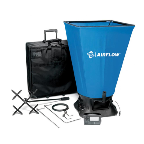
Airflow Instruments AV 30 User manual

1
AV30 OPERATING INSTRUCTIONS
Please read these instructions carefully before using the instrument. Shortform
instructions appear on the back of the instrument.
9021435/A/0805

2
1. INTRODUCTION
The AV30 is a rotating vane anemometer featuring digital display of
Velocity and Volume Flow rate in metric or imperial units.
1.1 The AV30 has been designed for ease of operation and has a menu
driven interface, it supports the following units of measurement:
m/s (metres per second)
m3/s (metres cubed per second)
l/s (litres per second)
m3/h (metres cubed per hour)
ft/min (feet per minute)
cfm (cubic feet per minute)
knots
mph (miles per hour)
km/h (kilometres per hour)
1.2 The AV30 has a 0-1 volt output proportional to velocity (0 to 30m/s) or
volume flow. This signal is created using a 12 bit DAC and so has a
small DC offset which should be taken into account when taking
readings. The cable connected to the 0-1 volt output should not be
more than 3 metres long.
2. BATTERY INFORMATION
2.1 The AV30 is supplied with batteries but these are not fitted into the
instrument.
Due to the limited shelf life the batteries are not covered by the TSI
Instruments Ltd. standard warranty.
To fit the batteries press firmly on the battery compartment cover and
slide it in the direction of the arrow.
Carefully insert the batteries into the holder checking the polarity of
each cell as marked on the holder and ensuring that the ribbon is
underneath all batteries. Refit the cover. The instrument is now ready
for use.
Do not leave discharged batteries in the instrument or the batteries in
place if the instrument is out of use for a long period of time.

3
2.2 Type of Batteries
4 x 1.5V AA batteries, standard, alkaline or rechargeable.
2.2.1 To Remove Batteries.
Remove the batteries from the holder by pulling on the ribbon or using
a thin screwdriver to ease them out.
2.2.4 Low Battery Indication
If the battery voltage falls below a pre-determined level, the display
will show battery symbols at both ends of the top line of the display.
The instrument will still operate correctly but only for a limited time so
the batteries should be replaced as soon as possible (Also use of the
backlight should be avoided to maximise remaining operating life of
the batteries).
3. TO USE THE INSTRUMENT
3.1 Instrument Menu
The Menu is set up with the following structure.
The and and the key are used to navigate between
different parts of the menu.
Enter
to select required function
to confirm selection
E
n
t
e
r

4
3.1.1 Read:
Select this mode to take measurements, to hold a reading press or
and to release and continue with new readings press or . To
leave this mode hold down the key for approx 2 seconds.
3.1.2 Select Units:
This mode allows you to switch between the different units supported
by the instrument, use the and keys to select the required unit
then the key to confirm selection.
3.1.3 Area Adjust:
Use the and keys to change the area to that required then press
the key to confirm selection.
3.1.4 Averaging:
Sets the amount of readings to be averaged, 1 to 10 in steps of one,
then 10 to 100 in steps of ten. Use the and keys to select the
level of averaging desired then press the key to confirm selection.
3.1.5 Backlight:
Turns on and off the screen backlight press the key to toggle
between these two modes.
3.2 Notes:
3.2.1 Incorrect readings may be displayed if the metal plate within the
anemometer ring is touched whilst using the instrument.
3.2.2 To display the instruments serial number and software version hold
down and turn the instrument on.
3.2.3 In averaging mode readings will be averaged at the desired level only
when this many readings have been taken, until this point the
instrument will average all available readings.
4. Where to use the instrument.
4.1 Checking air velocity or volume flow rate in small areas.
Enter
Enter
Enter
Enter
Enter
Enter

5
The instrument will function satisfactorily in an angular position but
should not be used in airstreams which are smaller than the entire face
area of the measuring head (113mm diameter). The AV30 is calibrated
for use in free air conditions. For smaller airstreams TSI Instruments
Ltd. thermal type anemometers are recommended.
4.2 Checking air velocity or volume flow rate over larger areas.
When checking air velocity or volume flow rate over larger areas, a
number of ‘spot’ readings should be taken and recorded to give
coverage over the whole area.
When taking ‘spot’ readings, it should be noted that quite large
variations might be observed between individual readings. In general,
the more readings taken, the more accurate the result will be. It does
not matter if the positions of the readings overlap somewhat, so long as
they are equally spread to cover the entire area.
5. Use on Grilles
Note: See Comments under section 7 ‘Possible sources of error’. Avoid
intrusion of the hand, arm or handle of the instrument into the face area of
the grille. The blockage effect created by this would cause artificially high
velocity over the remainder of the grille, leading to additional errors.
Better measuring conditions can be obtained on grilles with adjustable
direction vanes if the vanes on the grilles are temporarily straightened
before making measurements. This should not significantly affect the flow
rate so long as any built in dampers are not accidentally disturbed. It is
advisable to use the aperture, not the surface area of the grille in any flow
calculations.
The instrument is suitable for both supply and extract grilles, and the
procedure for both is the same except that the measuring head must be
rotated through 180oto align the direction arrow correctly.
Whilst it is acceptable to hold the anemometer head against the grille in
extract it is usually recommended to hold it slightly away from the grille
face on supply to avoid excessive turbulence and any vena-contracta
effects.

6
6. Use in Airways
In large airways the presence of the instrument will have a negligible
effect, but in small airways the blockage caused by the instrument, hand
and arm will cause the airstream to accelerate slightly as it passes the
rotating vane. This effect is somewhat variable depending on the size of
the airway and the distance from the duct walls. The error can be virtually
eliminated by mathematical correction to allow for the reduction of free
area caused by the obstruction. For this purpose the effective front area of
the instrument (not including hand or arm) can be taken as 0.019m2
(0.204ft2). The effect can be ignored completely if the duct exceeds about
500mm diameter (1’ 9”).
7. Possible sources of error
The above method ignores the effects of the reduced velocity at the duct
walls. A more precise method is shown in BS1042 Part 2.1 Log
Tchebycheff method.
This procedure is satisfactory for use in ducts, and at unobstructed
apertures.
Significant errors may occur if the aperture is covered by a grille,
particularly if this is of the type having adjustable direction vanes and/or
dampers. The airstream issuing from such a grille is invariably very
disturbed, consisting of many small areas of high velocity interspersed with
areas of low velocity.
The transitions between these areas are highly turbulent, and there may
even be some reversed flow. If maximum accuracy is required, it is
advisable to make up a short length of test ducting which is just larger than
the overall dimensions of the grille. This duct can be of any convenient
rigid material (eg stiff cardboard) and should have a length about twice the
diagonal measurement of the grille. The duct should be placed over the
grille, and sealed to the wall with adhesive tape. Measurements of flow can
now be conducted, as already described, at the unobstructed end of the test
duct. Use the cross sectional area of the duct (not the grille) for the
calculations.
It should be noted that using an AV30 instrument to take spot readings
across a duct as described earlier can result in an exaggerated velocity
indication in applications where there is a significant variation in velocities
across the test area. This is caused by the inability of the rotating vane to

7
slow down quickly when being moved from a higher velocity area to a
lower velocity area. It is quite common to experience situations where a
factor of 0.9 would have to be applied although this varies considerably.
For proportional balancing this does not matter but on quantitative
measurement it should be taken into consideration.
8. Uncertainty of Measurement
Due to characteristics common to all rotating vane anemometers, the
minute amount of bearing friction causes the head signal to depart from a
linear signal/velocity relationship by an insignificant amount at high
velocities but with progressively more effect below 2m/s (400 ft/mm). In
the AV30 range of instruments, means of compensation for this error is
provided in the software enabling accuracy to be maintained to within: 1
% of reading: 1 digit (with 100mm head).
WARNING; ALTERING THE CALIBRATION WILL INVALIDATE TSI
INSTRUMENTS LTD. RESPONSIBILITY FOR CALIBRATION UNDER
WARRANTY.
The unit will monitor each time the calibration is effected.
If the calibration routine is inadvertently entered then ABORT
immediately by switching the instrument OFF and then retry.
9. SERVICE AND RECALIBRATION
If a fault or the instrument’s calibration is suspected, it should be returned
to TSI Instruments Ltd. for repair or recalibration to original standards. In
any event, it is good practice to have the instrument checked at least once a
year. If an instrument is not working correctly or requires recalibration,
contact your nearest AIRFLOW INSTRUMENTS agent or UK. Service
Department on High Wycombe (01494) 459200 (International +44 1494
459200).
TSI Instruments Ltd. operates an Instrument Hire Service for the
convenience of customers having equipment repaired or recalibrated. If you
intend to take advantage of this facility please contact the Service
Department to make arrangements prior to returning your instrument.

8
10. CONTACTING TSI INSTRUMENTS LTD.
United Kingdom —QUALITY ASSURED TO ISO 9001
TSI Instruments Ltd.
Lancaster Road
Cressex Business Park
High Wycombe
Buckinghamshire.
HP12 3QP England
Telephone: +44 (0) 149 4 459200
Facsimile: +44 (0) 149 4 459700
E-Mail: [email protected]
WWW: http://www.airflowinstruments.co.uk
United States of America
TSI Incorporated
500 Cardigan Road
Shoreview, MN 55126 USA.
Telephone: 001-651-490-2811
Fax: 001-651-490-3824
WWW: http://www.tsi.com
The statements and opinions contained in this document are made in good faith. Whilst
every effort has been made to provide reliable information, TSI Instruments Ltd. does
not hold themselves responsible for possible errors of an editorial or other nature,
however caused. Should you require more detailed specification for a product
described herein, please contact our Sales Department. In view of our continuous
programme of improvement we reserve the right to change the specification for any
model or item described in this publication.

9
11. SPECIFICATION
PARAMETER
METRIC
IMPERIAL
Velocity –Ranges
*Accuracy
(100mm Head)
0.25 –30 m/sec
1 –110 km/h
0.5 –60 knots
Calibrated to better than
+/-1% of reading +/- 1
digit.
50 –6’000 ft/min
1 –70 mph
Calibrated to better than
+/-1% of reading +/- 1
digit.
Volume Flow- Ranges
* Accuracy
(100mm Head)
0.01 –2’700 m3/sec
1 –2’700’000 l/sec
1–9’720’000 m3/hr
Calibrated to better than
+/-1% of reading +/- 1
digit.
1 –5’500’000 ft3/min
Calibrated to better than
+/- 1% of reading +/- 1
digit.
Velocity –Ranges
*Accuracy
(35mm Head)
0.5 –20 m/sec
2 –70 km/h
1 –40 knots
Calibrated to better than
+/-2% of reading +/- 1
digit.
100 –4’000 ft/min
2- 45 mph
Calibrated to better than
+/-2% of reading +/- 1
digit.
Volume Flow- Ranges
* Accuracy
(35mm Head)
0.02 –1800 m³/sec
2 –1’800’000 l/sec
2 –6’480’000 m3/hr
Calibrated to better than
+/-2% of reading +/- 1
digit.
2 –3’700’000 ft3/min
Calibrated to better than
+/- 2% of reading +/- 1
digit.
Air Flow Area –Range
0.00399 –90.00 m²
0.04295 –900 ft²
Analogue Output
0 to 1V as standard proportional to 0 - 30m/s
(0 to 0.5V and 0 to 2V available on request)
Ambient Operating
Environment.
Barometric Pressure
500mb to 2 bar
Temp -10 to +50ºC
Barometric Pressure
15 in Hg to 60 in Hg
Temp 14 to 122ºF
Storage Temperature
-10 to +50ºC
14 to 122ºF
Dimensions of
Instrument
92 x 32 x 188mm
3.6 x 1.2 x 7.4inches
Weight of Instrument
(less batteries)
310 gms.
0.68lbs
Battery Cells
4 x 1.5V batteries type AA or equivalent standard
Alkaline or rechargeable.
Battery Life
Approximately 40 Hours using Alkaline battery cells

10
*Accuracy is at ambient conditions of 20ºC and 1013mb (68ºF and 30in Hg.)
CE Marking: This unit complies with the EEC Directive on Electromagnetic
Compatibility (EMC) 89/336/EEC.
Applied Harmonised Standards; EN50081-1 Radiated Emissions and
EN50082-1 Radiated and ESD Immunities.
QUALITY ASSURED TO ISO 9001
TSI Instruments Ltd. August 2005
Lancaster Road Part No. 9021435, Rev. A
Cressex Business Park
High Wycombe Tel: +44 (0) 149 4 459200
Buckinghamshire Fax: +44 (0) 149 4 459700
HP12 3QP England
WWW: http://www.airflowinstruments.co.uk TSI Incorporated
Table of contents
Other Airflow Instruments Measuring Instrument manuals
Popular Measuring Instrument manuals by other brands

Polar Electro
Polar Electro 7700-0001 instruction manual

Rigol
Rigol DSA1000 Series Accessories User Guide

HT Instruments
HT Instruments SOLAR03 user manual

Emerson
Emerson Rosemount 8800D Series Reference manual

PCB Piezotronics
PCB Piezotronics 214B Installation and operating manual

Concoa
Concoa Advantium 16 Installation and operating instructions