manuals.online logo
Brands
  1. Home
  2. •
  3. Brands
  4. •
  5. Eaton
  6. •
  7. Measuring Instrument
  8. •
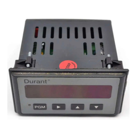
  9. Eaton Durant 47000-400 Operating and maintenance instructions

Eaton Durant 47000-400 Operating and maintenance instructions

Durant Model 47000-400/401
Manual 47000-900-02
GENERAL DESCRIPTION
The Durant Series 47000 Ratemeter is a four digit, all solid
state event per unit time meter. The display is .43” LED
displays, provision is made to light a decimal point
between the units and tens displays. It operates from 115V
60 Hz (400) or 230V 50 Hz (401) power and is capable of
working with a broad range of AC and DC input signals
(.018-141V). It can operate directly from most magnetic
pickups or from 5 VDC signals (TTL) and from 15 VDC
signals (CMOS). The input signals can be doubled (x2) at
the user’s discretion. It supplies 15 VDC power for many
solid state transducers.
The input signals (counts) are accumulated for one second
of time, then the accumulated count is displayed while a
new sample is being accumulated. The basic time is
generated by the power line.
All connections are made to seven rear panel screw
terminals and all user options or selections are made via
slide switches on the rear panel. Panel mounting is
accomplished by inserting the unit through a panel cutout.
SPECIFICATIONS
POWER INPUT
47000-400: 108-132 VAC, 60 Hz
47000-401: 216-264 VAC, 50 Hz 10 Watts
POWER OUTPUT
15 V ± .6 VDC, 50 ma max. for power transducers.
+ at Logic 15 VDC
- at Logic Com.
SIGNAL INPUT
IN 1: 0-10,000 Hz
The count is entered (counted) when the voltage drops
below the lower switch point of 1.9 ± .5 volts. The
voltage must rise to more than .05 volts above the
lower switch point between counts.
25,000 ohms input impedance
100 VAC/DC max., continuous voltage
IN 1 and IN 2: 0-10,000 Hz
This input combination requires a true AC signal
(magnetic pickup) of .018 V min. (.050 V p-p). A
maximum of 141 VAC may be applied.
50,000 ohms input impedance.
141 VAC (400 V p-p) max. continuous voltage.
IN 3: 0-5,000 Hz (with dip switch #3 OFF, 3 switch
group)
Input device must sink current (conduct) to “LOGIC
COM” from a 15 VDC source.
17 ma inrush, 2 ma steady state
Minimum ON or sink time: 25 microseconds
Minimum OFF or nonconductive time: 175
microseconds.
0-150 Hz (with dip switch #3 ON, 3 switch group)
17 ma inrush, 2 ma steady state
Minimum ON or sink time: 1 millisecond
Minimum OFF or nonconductive time: 5 milliseconds.
UNIT OF TIME
The sample time is one second. Accuracy—dependent
on line frequency.
DECIMAL POINT
A decimal point can be lighted between the units and
tens display by turning on dip switch #1, 3 switch
group.
DOUBLING
The count is entered on the negative signal transition
or on the negative and on the positive signal
transitions as chosen by the position of switch #2.
This provides two counts for each input cycle when
switch #2 is ON.
WIRING
1. Disconnect all power before making any wiring
connections or changes.
2. Keep all signal wires as short as possible and away
from other wires.
3. Connect any shields on signal wires to “LOGIC COM.”
4. Connect power to “AC INPUTS”
47000-400: 115 VAC, 60 Hz
47000-401: 230 VAC, 50 Hz
5. Connect signal input:
A. AC signal .018-141 V from magnetic pickup or
other AC generator.
47004-400
47000-4XX Mag Pickup Other
IN 1 Red A
IN 2 Black B
Logic Com. Shield Shield
With this connection, the IN 1 and IN 2 leads can be
interchanged. The AC signal must not be referenced
or connected to the shield.
B. Low level AC/DC signal:
Connect the + signal to IN 1.
Connect the - signal to LOGIC COM.
This signal must provide a voltage greater than 2.4
V when high and less than 1.4 V when low across
a 25,000 ohm load. This type signal is typically
provided by a TTL device. This voltage may be
100 VAC or DC maximum.
C. Switch or current sinking signal:
IN 3: Either lead from a switch or the signal lead
from a current sinking device. This will be a +
voltage point.
LOGIC COM: The other switch lead or the
common lead from a current sinking device.
A switch or transistor provides a good input at this
terminal. The open circuit voltage is 15 VDC and
the current into a resistor load is 17 ma decaying
to 2 ma steady state. The voltage drop across the
switch or transistor should be less than 1.0 V.
Never apply over 15 V to this terminal.
Durant Model 47000-400/401
Manual 47000-900-02
Typical input devices:
49400-400 Vane Pickup
49970-400 Proximity Sensor
ES-9513-RS Contactor
39700-XXX Shaft Encoder
48063-XXX Shaft Encoder
39200-400 Mini Photo Sensor
49160-401 Retro Reflective Photocell
Hall Effect Switches and Chips
6. Signal Input
The number displayed is the number of cycles of input
signal each second, or two times the number of cycles
of input signal each second if the DOUBLER (Switch
2) in ON. The DOUBLER is most practical when the
waveform of the input signal is ON. The DOUBLER
produces a count on the negative edge and a second
count on the positive edge of the input signal. If these
edges are close together (from a pulse) with a larger
time to the next edge, the display may show a two
count variation when the actual input rate is constant.
The count rate (CPS) is equal to the number displayed
— the signal rate may equal 1/2 the number displayed.
Since the sample time of one second is equal to 1/60
of a minute, on installations indicating events per
minute, you must have an input device generating 60
counts per event.
Pulse/Item Calculation
To Measure: Double Switch OFF Double Switch ON
Items/Second 1 pulse/item .5 pulses/item
Items/Minute 60 pulses/item 30 pulses/item
Items/Hour 3600 pulses/item 1800 pulses/item
Items can be: Revolutions, Feet, Inches, Yards, Gallons,
etc.
TROUBLESHOOTING
1. No Display
If the display does not light and show 0000 when the
AC power is applied, check the wiring to the “AC
INPUT” terminals and check to insure that the correct
power is getting to the unit.
2. No Count from IN 1 and IN 2
Disconnect all power to the unit and remove all
connections to IN 1, IN 2, and IN 3. Place all the rear
panel switches in the ON position. Jumper IN 1 and IN
2 to the two AC INPUT terminals. Reapply AC power
and within eight seconds the display should show 12.0
if on 60 Hz power or 10.0 if on 50 Hz power. If this is
satisfactory, check your signal for IN 1 — IN 2.
3. No Count from IN 1
Disconnect all power to the unit and remove all
connections to IN 1, IN 2 and IN 3. Place all rear panel
switches in the ON position. Re-apply AC power and
with a short piece of wire make momentary
connections from IN 1 to LOGIC = 15 VDC. The
display should show 00.2 for each make and break of
the connections in a one second Sample Time. If this
is satisfactory, check your signal for IN 1.
4. No Count from IN 3
Disconnect all power to the unit and remove all
connections to IN 1, IN 2 and IN 3. Place all rear panel
switches in the ON positions. Re-apply AC power and
with a short piece of wire make momentary
connections from IN 3 to LOGIC COM. The display
should show at least 00.2 for each make and break of
the connection in a one second Sample Time. If this is
satisfactory, check your signal at IN 3.

This manual suits for next models

1

Other Eaton Measuring Instrument manuals

Eaton SEFELEC 1500M User manual

Eaton

Eaton SEFELEC 1500M User manual

Eaton Crouse-hinds series User manual

Eaton

Eaton Crouse-hinds series User manual

Eaton Durant Eclipse 5775X-40 Series User manual

Eaton

Eaton Durant Eclipse 5775X-40 Series User manual

Eaton PXM4K Series User manual

Eaton

Eaton PXM4K Series User manual

Eaton LifeSense User manual

Eaton

Eaton LifeSense User manual

Eaton Eclipse Series User manual

Eaton

Eaton Eclipse Series User manual

Eaton xStorage Home Series User manual

Eaton

Eaton xStorage Home Series User manual

Eaton IQ 35M Series User manual

Eaton

Eaton IQ 35M Series User manual

Eaton InsulGard User manual

Eaton

Eaton InsulGard User manual

Eaton 2075 User manual

Eaton

Eaton 2075 User manual

Eaton RMQ compact solution Manual

Eaton

Eaton RMQ compact solution Manual

Eaton Crouse-Hinds MTL Z230 User manual

Eaton

Eaton Crouse-Hinds MTL Z230 User manual

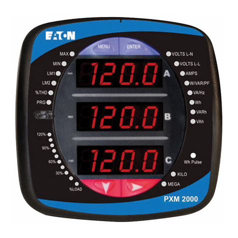
Eaton Power Xpert Meter 2000 User manual

Eaton

Eaton Power Xpert Meter 2000 User manual

Eaton Crouse-hinds series User manual

Eaton

Eaton Crouse-hinds series User manual

Eaton Cutler-Hammer TD 17530A Programming manual

Eaton

Eaton Cutler-Hammer TD 17530A Programming manual

Eaton KK650 User manual

Eaton

Eaton KK650 User manual

Eaton IQ 150S Guide

Eaton

Eaton IQ 150S Guide

Eaton K1650 User manual

Eaton

Eaton K1650 User manual

Eaton Power Xpert PXM 4000 User manual

Eaton

Eaton Power Xpert PXM 4000 User manual

Eaton Crouse-Hinds Z130 User manual

Eaton

Eaton Crouse-Hinds Z130 User manual

Eaton Crouse-hinds series User manual

Eaton

Eaton Crouse-hinds series User manual

Eaton SONiX Pm10 User manual

Eaton

Eaton SONiX Pm10 User manual

Eaton PXBCM-MB Manual

Eaton

Eaton PXBCM-MB Manual

Eaton Power Xpert C445 Manual

Eaton

Eaton Power Xpert C445 Manual

Popular Measuring Instrument manuals by other brands

PCE Instruments PCE-228LIQ manual

PCE Instruments

PCE Instruments PCE-228LIQ manual

Sekonic FLASHMATE L-308BII operating instructions

Sekonic

Sekonic FLASHMATE L-308BII operating instructions

Keysight SR101EDUA user guide

Keysight

Keysight SR101EDUA user guide

BIRD Thruline 43 Instruction book

BIRD

BIRD Thruline 43 Instruction book

Johnson Controls EMCOMMS Series installation instructions

Johnson Controls

Johnson Controls EMCOMMS Series installation instructions

Newport INFINITY INFCR Operator's manual

Newport

Newport INFINITY INFCR Operator's manual

Tektronix 6 series instructions

Tektronix

Tektronix 6 series instructions

Motorola R-2200 Operator's manual

Motorola

Motorola R-2200 Operator's manual

Keithley SourceMeter 2600B Series quick start guide

Keithley

Keithley SourceMeter 2600B Series quick start guide

LDG TW-1 user manual

LDG

LDG TW-1 user manual

Agilent Technologies ICP-MS Series Troubleshooting

Agilent Technologies

Agilent Technologies ICP-MS Series Troubleshooting

Bosworth SapCheck user guide

Bosworth

Bosworth SapCheck user guide

PRGR RED EYES POCKET HS-120A user manual

PRGR

PRGR RED EYES POCKET HS-120A user manual

Endress+Hauser Promag 300 instructions

Endress+Hauser

Endress+Hauser Promag 300 instructions

Lorrca MaxSis user manual

Lorrca

Lorrca MaxSis user manual

IFM Electronic efector300 SI5000 operating instructions

IFM Electronic

IFM Electronic efector300 SI5000 operating instructions

Chauvin Arnoux C.A 6549 user manual

Chauvin Arnoux

Chauvin Arnoux C.A 6549 user manual

Conrad 67 25 06 operating instructions

Conrad

Conrad 67 25 06 operating instructions

manuals.online logo
manuals.online logoBrands
  • About & Mission
  • Contact us
  • Privacy Policy
  • Terms and Conditions

Copyright 2025 Manuals.Online. All Rights Reserved.