manuals.online logo
Brands
  1. Home
  2. •
  3. Brands
  4. •
  5. MARTINDALE
  6. •
  7. Measuring Instrument
  8. •
  9. MARTINDALE FD650/R User manual

MARTINDALE FD650/R User manual

ELITE FUSE FINDER KIT
MARTINDALE
ELECTRIC
Trusted by professionals
INSTRUCTIONS
SAFETY INFORMATION: Always read before proceeding.
WARNING
These instructions contain both information and warnings that are
necessary for the safe operation and maintenance of the FD650/R and
FD500/T or FD600/T. It is recommended that you read the instructions
carefully and ensure that the contents are fully understood. Failure to
understand the instructions and to comply with the warnings and
instructions contained herein can result in serious injury, damage or
even death.
In order to avoid the danger of electrical shock, it is important that
proper safety measures are taken when working with voltages
exceeding 30 V AC rms, 42 V AC peak or 60 V DC.
The FD650/R and FD500/T FD600/T must only be used under the
conditions and for the purposes for which they have been
constructed. Particular attention should be paid to the safety
instructions, the technical specifications and the use of the FD650/R
and FD500/T or FD600/T in dry surroundings.
Always check the FD650/R and FD500/T or FD600/T are in good
working order before use and that there are no signs of damage to
any unit. Do not use if damaged.
Keep these instructions for future reference. Updated instructions
and product information are available on our website:
www.martindale-electric.co.uk
Symbols AC (alternating current)
Earth ground
Safety information (refer to the manual)
Equipment complies with relevant EU directives
2
CONTENTS
1. Introduction
1.1 Description
1.2 Unpacking and Inspection
1.3 Battery Installation
2. Technical Specification
2.1 Transmitter
2.2 Receiver
3. Operation
3.1 Precautions
3.2 Description of Functions and Indicators
3.3 Using the FD650/R and FD500/T or FD600/T as a
Fuse Finder
3.3.1 Pre-Check of the FD650/R and FD500/T or FD600/T
3.3.2 Locating a Fuse or Circuit Breaker
3.3.3 Using in Manual Threshold Mode
3.3.4 Using in Automatic Threshold Mode
3.3.5 Connecting the FD600/T using TL83 & TL88 Leads
3.4 Using the FD650/R as a Voltage Detector
3.4.1 Pre-Check of the FD650/R
3.4.2 Locating Live Wiring/Cabling
4. Maintenance
4.1 Battery Replacement
4.2 Cleaning
4.3 Repair & Service
4.4 Storage Conditions
4.5 Warranty
N.B. The unit defaults to Manual Mode when switched on (see
sections 3.3.3 and 3.3.4).
3
1. INTRODUCTION
1.1 Description
The FD650/R is a combined AC voltage detector and fuse finder receiver
(when used in combination with the FD500/T or FD600/T transmitter).
As a fuse finder the FD650/R can be operated with either manual or
automatic setting of its sensitivity threshold to find the fuse or circuit
breaker that produces the maximum signal.
In manual mode the press of a push-button will set the sensitivity threshold
to bring the detected signal to mid scale on the bar graph.
In automatic mode the FD650/R will automatically set the sensitivity
threshold every time a signal of a greater magnitude is detected, to bring it
onto the bar graph scale.
In either mode the buzzer will continue to sound when a signal is present,
even when the signal is too small to be shown on the bar graph due to the
sensitivity setting.
When in the voltage detector mode the FD650/R employs the bar graph to
show the detected signal, and at the same time activates the buzzer. The
voltage detector function also has a built in test signal to check the
operation of its circuitry.
Other features of the FD650/R are Auto Power-down and Low Battery
Indication.
A three-position switch sets the FD650/R from OFF to either the Fuse
Finder or the Voltage Detector functions. A single push-button switch
controls all other operations of the FD650/R.
4
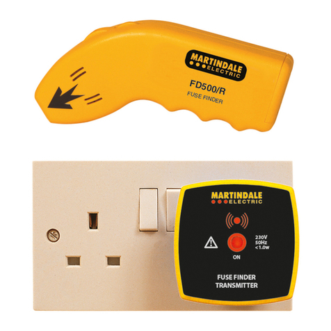
Fig. 1. FD500/T Fig. 2. FD600/T with EX332
Mains Lead
Fig. 3. FD650/R
1.2 Unpacking and Inspection
Before unpacking the FD650/R and FD500/T or FD600/T, examine the
shipping carton for any sign of damage. Unpack and inspect the FD650/R
and FD500/T or FD600/T for any damage. If there is any damage then
consult your distributor immediately.
1.3 Battery Installation
Refer to Section 4.1 for battery installation instructions for the FD650/R.
5
2. TECHNICAL SPECIFICATION
2.1 Transmitter (FD500/T & FD600/T)
Nominal supply voltage: 230 V.
Frequency range: 30 - 70 Hz.
Switching frequency: Approx 5 Hz.
Temperature Range: -10 to 40C non-condensing.
Dimensions: Approx 65 x 65 x 50mm.
Weight: Approx 60g.
Earth leakage: Nil.
Power supply: From mains.
Power consumption: Approx 1 W.
Fuse rating 500 mA.
Overvoltage category: Cat III/300V.
Pollution degree: 2.
Protection class: IP20.
Safety: Complies to BS EN 61010-1:1993
2.2 Receiver (FD650/R)
Fuse Finder Function
Tracing depth for fuse assignment: Up to 10cm, depending on local
conditions.
Sensitivity threshold setting: Automatic, or manual push button.
Voltage Detector Function
Voltage range: 40V - 600 V AC.
Frequency range: 50 Hz - 1 kHz.
Voltage sensitivity: Table 1 below gives the typical distance at
which the FD650 will illuminate the first bar
graph segment and activate the buzzer.
6
Table 1. Typical Sensing Distance of Energised Cable
Cable Type 115V, 50Hz 230V, 50Hz
Flat 1mm2Twin & Earth 3mm 23mm
2.5mm2Twin & Earth 3mm 23mm
Round 1.5mm22mm 18mm
General
Temperature Range: -10 to 40C, non-condensing.
Dimensions: 202 x 32 x 22mm.
Weight: Approx 135g (including battery).
Protection class: IP20.
Power supply: 9V battery, MN1604/PP3, IEC 6LA61
(alkaline only).
Low battery level: Approx 6.9V.
Auto power down current drain: Typically 20 μA.
3. OPERATION
3.1 Precautions
Warning Before use check the FD650/R and FD500/T or FD600/T for
cracks or any other damage, and make sure the units are free from dust,
grease and moisture.
Warning Hold the FD650/R by the bottom of the unit. Do not allow your
fingers to go beyond the LED indicators.
Warning Do not use if the battery cover is not fitted.
Warning Always perform a pre-check on the FD650/R and FD500/T or
FD600/T (see sections 3.3.1 and 3.4.1) before use.
7
Caution Where users have a Martindale kit that includes an E-Ze Check
Xtra or an E-Ze Test, do not have these or similar types of unit plugged in
when fuse finding.
Caution Avoid severe mechanical shock or vibration and extreme
temperature.
Caution Remove the batteries from the FD650/R when not in use for an
extended period to avoid corrosion from leaking batteries.
3.2 Description of Functions and Indicators
Auto Power Down:- The power down is activated after approximately 5
minutes without a valid signal. The power down mode can only be reset by
switching the unit OFF and then on again. In power down mode the typical
current drawn is 20μA.
The power down function can be deactivated by holding down the press
button when switching the unit on.
Buzzer:- An internal buzzer is used to inform the user when a signal has
been detected. In the fuse finder function the buzzer will continue to sound
even if the LED’s are not illuminated, provided that a signal is present.
Function Selection:- The required function is selected by sliding the three-
position slide switch from OFF to FIND (Fuse Finder) or VAC (Voltage
indicator).
1.1. LED’s:- There are two status LED’s on the LHS of the unit. The top
one is green and shows battery status. Continuous illumination means that
the battery level is acceptable. Flashing means that the battery should be
replaced.
1.2. The red LED is only used for the FIND function and indicates that the
unit is in automatic sensitivity mode.
8
A bar graph of 6 red LED’s on the RHS of the unit is used in both FIND and
VAC functions to display the signal strength.
1.3. Low Battery:- If the battery voltage is lower than a pre-set level of
6.9V the Green status LED flashes every 500ms. The battery should be
replaced (see section 4.1).
1.4. Push -button Switch:- Used to activate the following functions:-
1.5. Activation of test signal in VAC function.
1.6. Automatic threshold mode – in FIND function hold down push-button
for 2 seconds.
Auto mode bar graph centring – momentarily press to set the bar graph
indication to the centre of the scale when using the FIND function.
Deactivation of battery power down – hold down while switching from OFF
to FIND or VAC.
Manual mode threshold – momentarily press to set a new threshold when
using the FIND function in presence of signal.
Resetting sensitivity threshold - When out of signal range momentarily
press to set the sensitivity threshold to the power-up default level when
using the FIND function.
9
3.3 Using the FD650/R and FD500/T or FD600/T as a
Fuse Finder
Ensure you have read the precautions (Section 3.1) before proceeding.
3.3.1 Pre-Check of the FD650/R and FD500/T or FD600/T
Plug the FD500/T or FD600/T transmitter into a known socket and ensure
the red ON indicator is illuminated.
Switch the FD650/R receiver to FIND and verify the green battery indicator
is continuously illuminated. If the green battery indicator is flashing the
battery is low and should be replaced (see section 4.1).
Hold the FD650/R in close proximity to the transmitter and verify
illumination of the FD650/R SIGNAL bar graph and that an audible tone is
present. The number of illuminated segments of the bar graph will depend
on the FD650/R position and orientation with respect to the transmitter.
Do not use if the pre-check fails.
3.3.2 Locating a Fuse or Circuit Breaker
Plug the FD500/T or FD600/T into a socket of the circuit to be traced and
ensure the red ON indicator is illuminated. If you are using the FD600/T
with TL83 or TL88 leads refer to section 3.3.5.
Switch the FD650/R to FIND and verify the green battery indicator is
continuously illuminated.
When switched to FIND, the FD650/R defaults to the manual threshold
mode (see section 3.3.3). The FD650/R can alternatively be operated in the
automatic threshold mode (see section 3.3.4).
N.B. The unit defaults to Manual Mode when switched on (see
sections 3.3.3 and 3.3.4).
10
3.3.3 Using in Manual Threshold Mode
Hold the FD650/R receiver in close proximity to the box suspected of
housing the fuse or circuit breaker being sought. If the signal is present an
audible tone will be emitted from the FD650/R.
Hold the FD650/R against the first fuse or circuit breaker of the box as
shown in figure 4. The orientation of the FD650/R in relation to the fuse /
breaker must be as shown in figure 4 and it should be held in the centre of
the fuse or circuit breaker.
Depending on the signal strength the bar graph may be activated. Press
the SET button to set the sensitivity and the lower 3 to 4 segments of the
bar graph will be illuminated.
Move along the row of fuses/circuit breakers, stopping at the centre of each
fuse/circuit breaker and noting the signal strength on the bar graph display.
Every time this signal causes the bar graph to exceed 3 to 4 segments,
press the SET button to set the new sensitivity threshold.
Be sure to check all the fuses/circuit breakers, and then go back over all
the fuses/circuit breakers. Only one fuse/circuit breaker should now show a
signal strength indication on the bar graph. If this is not the case then
repeat the above procedure, until only a single fuse/circuit breaker causes
an indication.
Switch off/remove the fuse/circuit breaker that shows the maximum signal
strength and check that the FD650/R bar graph is no longer illuminated and
the audible tone is no longer present when the fuse / circuit breaker
location is re-checked.
Go to the transmitter, if the correct fuse/circuit breaker has been switched
off/removed then the red ON indicator should no longer be illuminated.
11
Figure 4. Correct
The receiver must be held
in this orientation in relation
to the breaker to find the
correct fuse/circuit breaker.
If the individual breakers
were horizontal, the
receiver would have to
rotated through 90° (in
either direction).
Figure 5. Wrong
12


3.3.4 Using in Automatic Threshold Mode
With the selector switch set to FIND, hold down the SET button for
approximately 2 seconds until the red MODE indicator is illuminated.
Hold the FD650/R receiver in close proximity to the box suspected of
housing the fuse, or circuit breaker, being sought. If the signal is present an
audible tone will be emitted from the FD650/R.
Hold the FD650/R against the first fuse or circuit breaker of the box as
shown in figure 4. The orientation of the FD650/R in relation to the fuse /
breaker must be as shown in figure 4 and it should be held in the centre of
the fuse or circuit breaker.
The FD650/R will automatically set the sensitivity threshold to show a
signal strength indication on the bar graph. The signal strength indication
on the bar graph may be centred to display 3 to 4 segments at any time by
pressing the SET button.
Be sure to check all the fuses/circuit breakers, and then go back over all
the fuses/circuit breakers maintaining uniform proximity during and after
each pass to prevent incorrect re-setting of the receiver sensitivity. Only
one fuse/circuit breaker should now show a signal strength indication on
the bar graph. If this is not the case then repeat the above procedure, until
only a single fuse/circuit breaker causes an indication.
Switch off/remove the fuse/circuit breaker that shows the maximum signal
strength and check that the FD650/R bar graph is no longer illuminated and
the audible tone is no longer present. Go to the transmitter, if the correct
fuse/circuit breaker has been switched off/removed then the red ON
indicator should no longer be illuminated.
3.3.5 Connecting the FD600/T using TL83 or TL88 Leads
If you are using the FD600/T with TL83 leads to trace wiring, connect the
black crocodile clip to neutral and red to live in that order and then plug the
TL83 lead into the FD600/T IEC inlet socket.
13
Optionally TL88 leads can also be used with the FD600/T. Connect the
black crocodile clip to neutral and red to live in that order and then plug the
TL88 lead into the FD600/T IEC inlet socket. The green crocodile clip
should be clipped to earth as a safety measure.
Fig. 6. TL83 Leads Fig. 7. TL88 Leads
3.4 Using the FD650/R as a Voltage Detector
Ensure you have read the precautions (section 3.1) before proceeding.
3.4.1 Pre-Check of the FD650/R
Switch the FD650/R to VAC and verify the green battery indicator is
continuously illuminated. If the green battery indicator is flashing the battery
is low and should be replaced (see section 4.1).
Press the FD650/R TEST button and verify all the segments of the
FD650/R VAC bar graph are illuminated and an audible tone is present.
Do not use if the pre-check fails.
14
3.4.2 Locating Live Wiring/Cabling
Switch the FD650/R to VAC and verify the green battery indicator is
continuously illuminated.
Hold the tip of the FD650/R to the cabling to be tested. Where multi-core
cabling is being tested run the tip of the FD650/R along a short length of
the cable to overcome the electrical effects of the natural twist in the
conductors.
If the wiring/cabling is live the VAC bar graph will display an indication and
an audible tone will be emitted from the FD650/R.
4. MAINTENANCE
4.1 Battery Replacement
Remove the rear battery cover of the FD650/R by unscrewing the battery
cover retaining screw. The cover will now lift off.
Fit a new 9V, MN1604/PP3 alkaline battery, observing correct polarity.
Replace the battery cover and secure with the battery cover retaining
screw.
4.2 Cleaning
The FD650/R and FD500/T or FD600/T may be cleaned using a soft damp
cloth and mild detergent.
Do not use abrasives or solvents. Allow to completely dry before using.
4.3 Repair & Service
There are no user serviceable parts in this unit. Return to Martindale
Electric Company Ltd if faulty. Our service department will promptly quote
to repair any faults that occur outside the warranty period.
15
4.4 Storage Conditions
The FD650/R and FD500/T or FD600/T should be kept in warm dry
conditions away from direct sources of heat or sunlight, with the battery
removed and in such a manner as to preserve the working life of the
FD650/R and FD500/T or FD600/T. It is strongly advised that the unit is not
kept in a tool box where other tools may damage it.
4.5 Warranty
Faults in manufacture and materials are fully guaranteed for 2 years from
date of invoice and will be rectified by us free of charge, provided the unit
has not been tampered with, and is returned to us with its housing
unopened. Damage due to dropping, abuse or misuse is not covered by the
guarantee. Nothing in these instructions reduces your statutory rights.
Other products from Martindale:
Martindale Electric Company Limited
Metrohm House, Imperial Park, Imperial Way,
Watford, Herts, WD24 4PP, UK
Tel: +44(0)1923 441717 Fax: +44(0)1923 446900
E-mail:[email protected]
Website: www.martindale-electric.co.uk
© Martindale Electric Company Ltd. 2016Registered in England No. 3387451. Rev 2.
G18th Edition Testers
GAll-in-one’s
GCalibration Equipment
GContinuity Testers
GElectrician’s kits
GFull Calibration & Repair
Service
GFuse Finders
GDigital Clamp Meters
GDigital Multimeters
GMicrowave Leakage Detectors
GMotor Maintenance
Equipment
GNon-trip loop testers
GPat testers & Accessories
GPhase rotation
GProving units
GSocket Testers
GThermometers & Probes
GTest Leads
GVoltage Indicators
GSpecialist Metrohm testers
(4 & 5kV)
GSpecialist Drummond testers
This manual suits for next models

2

Other MARTINDALE Measuring Instrument manuals

MARTINDALE VIPD138 User manual

MARTINDALE

MARTINDALE VIPD138 User manual

MARTINDALE PSI4000 User manual

MARTINDALE

MARTINDALE PSI4000 User manual

MARTINDALE CM58 User manual

MARTINDALE

MARTINDALE CM58 User manual

MARTINDALE FD500 User manual

MARTINDALE

MARTINDALE FD500 User manual

MARTINDALE PD430 User manual

MARTINDALE

MARTINDALE PD430 User manual

MARTINDALE AV90 User manual

MARTINDALE

MARTINDALE AV90 User manual

MARTINDALE CO90 User manual

MARTINDALE

MARTINDALE CO90 User manual

MARTINDALE CB12 User manual

MARTINDALE

MARTINDALE CB12 User manual

MARTINDALE FD500 User manual

MARTINDALE

MARTINDALE FD500 User manual

MARTINDALE VR2230 Operator's manual

MARTINDALE

MARTINDALE VR2230 Operator's manual

MARTINDALE CM87 User manual

MARTINDALE

MARTINDALE CM87 User manual

MARTINDALE CMi210 User manual

MARTINDALE

MARTINDALE CMi210 User manual

MARTINDALE CO190 User manual

MARTINDALE

MARTINDALE CO190 User manual

MARTINDALE RT80 User manual

MARTINDALE

MARTINDALE RT80 User manual

MARTINDALE VT7 User manual

MARTINDALE

MARTINDALE VT7 User manual

MARTINDALE VI13700G User manual

MARTINDALE

MARTINDALE VI13700G User manual

MARTINDALE SP75 User manual

MARTINDALE

MARTINDALE SP75 User manual

MARTINDALE DC50 User manual

MARTINDALE

MARTINDALE DC50 User manual

MARTINDALE CM79 User manual

MARTINDALE

MARTINDALE CM79 User manual

MARTINDALE LM82 User manual

MARTINDALE

MARTINDALE LM82 User manual

MARTINDALE LM192 User manual

MARTINDALE

MARTINDALE LM192 User manual

MARTINDALE LM90 User manual

MARTINDALE

MARTINDALE LM90 User manual

MARTINDALE CT60 User manual

MARTINDALE

MARTINDALE CT60 User manual

MARTINDALE CM82 User manual

MARTINDALE

MARTINDALE CM82 User manual

Popular Measuring Instrument manuals by other brands

Elvaco CMi6140 quick start guide

Elvaco

Elvaco CMi6140 quick start guide

SKF MicroVibe P CMVL 3860-ML user manual

SKF

SKF MicroVibe P CMVL 3860-ML user manual

BIRD Termaline 8930 Series Operation manual

BIRD

BIRD Termaline 8930 Series Operation manual

Ankom ANKOM200 FIBER ANALYZER Operator's manual

Ankom

Ankom ANKOM200 FIBER ANALYZER Operator's manual

Hach sensION+ pH3 manual

Hach

Hach sensION+ pH3 manual

Hanna Instruments HI 718 manual

Hanna Instruments

Hanna Instruments HI 718 manual

Crowcon M07630 user manual

Crowcon

Crowcon M07630 user manual

Eastron SDM230-LoRaWAN user manual

Eastron

Eastron SDM230-LoRaWAN user manual

PCB Piezotronics 357B83 Installation and operating manual

PCB Piezotronics

PCB Piezotronics 357B83 Installation and operating manual

ThermoWorks ThermaQ Blue operating instructions

ThermoWorks

ThermoWorks ThermaQ Blue operating instructions

natus Madsen Astera 2 user guide

natus

natus Madsen Astera 2 user guide

Fluke SONOCHEK operating instructions

Fluke

Fluke SONOCHEK operating instructions

Reed Instruments SMART Series instruction manual

Reed Instruments

Reed Instruments SMART Series instruction manual

PASCO PASPORT PS-2152 instruction manual

PASCO

PASCO PASPORT PS-2152 instruction manual

Contrel EMA-90N user manual

Contrel

Contrel EMA-90N user manual

DayTronic 3000 series instruction manual

DayTronic

DayTronic 3000 series instruction manual

Blue-White industries F-1000 instruction manual

Blue-White industries

Blue-White industries F-1000 instruction manual

Presys DMY-2030 Light Technical manual

Presys

Presys DMY-2030 Light Technical manual

manuals.online logo
manuals.online logoBrands
  • About & Mission
  • Contact us
  • Privacy Policy
  • Terms and Conditions

Copyright 2025 Manuals.Online. All Rights Reserved.