Concoa Advantium 16 User manual

ADI 9531-H
Advantium 16 System
Monitor
INSTALLATION AND OPERATING INSTRUCTIONS
Carefully Read These Instructions Before Operating
Carefully Read These
Controls Corporation of America
1501 Harpers Road • Virginia Beach, VA 23454
Telephone 1-800-225-0473 or 757-422-8330 • Fax 757-422-3125
www.concoa.com
March 2020
Revision H

SAFETY
BASIC SAFETY PRECAUTIONS MUST BE FOLLOWED TO REDUCE THE RISK OF
FIRE, ELECTRICAL SHOCK OR INJURY.
While the Advantium16 is dust and moisture resistant, it is NOT water-proof or
completely sealed. It should be installed where it will not be subjected to rain or
high concentrations of dust. Never pour or spray liquids directly onto the product.
Install the Advantium16 where the ambient temperature range is between 0° F and
140° F.
THIS PRODUCT IS NOT INTENDED FOR USE IN EXPLOSIVE
ENVIRONMENTS.
DO NOT INSTALL THIS PRODUCT IN ANY HAZARDOUS ENVIRONMENT.
If product appears damaged in any way, do not use and request service from
CONCOA.
USER RESPONSIBILITY
Service to this product should only be performed by CONCOA or an authorized
CONCOA agent. Requests for service may be made through CONCOA CUSTOMER
SERVICE at 1-800-225-0473. Written requests may be made using CONCOA’s FAX
CONCOA accepts no responsibility for damage or injury if this product is modified in
any way.
CONCOA assumes/accepts no liability or responsibility for damage to individuals or
equipment that may occur when using this product

1
Index
Power Requirements............................................................................................................2
Alarm Relay Specifications .................................................................................................2
Understanding Alarm Operation..........................................................................................3
Mounting Requirements.......................................................................................................5
Installation Instructions........................................................................................................6
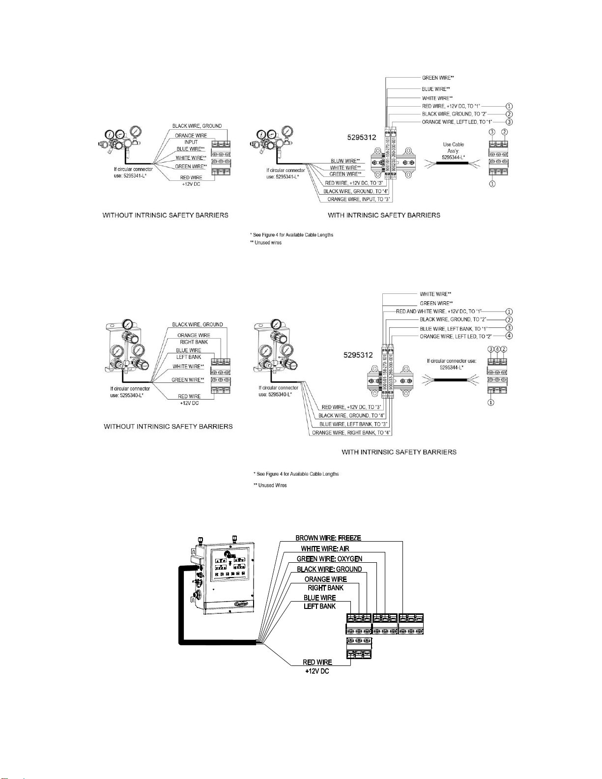
Connecting External Input Devices to the Advantium 16...................................................6
Connecting Alarm Outputs................................................................................................11
Setting Remote Alarm Outputs..........................................................................................12
Muting Audible Alarm.......................................................................................................14
Real Time Clock................................................................................................................14
Configuration using the WebServer...................................................................................15
Status Page.........................................................................................................................15
View Settings Page............................................................................................................16
Change Settings Tab..........................................................................................................17
Configuration Page ....................................................................................................17
Inputs Page.................................................................................................................18
Input Groups Page......................................................................................................19
Output Relays Page....................................................................................................21
E-mail Alerts Page.....................................................................................................22
Security Page .....................................................................................................................24
Networking Page................................................................................................................25
Warranty Information ........................................................................................................26

2
POWER REQUIREMENTS
Input Voltage: External Power Supply
Universal input voltage 100-240 VAC, 50/60Hz.
Power Consumption: 8 watts
ALARM OUTPUT RELAY SPECIFICATIONS:
Contacts: Normally Open/ Normally Closed (selectable) Dry Contact
Contact Rating: 24 volts DC @.5 amps Max.

3
UNDERSTANDING ALARM OPERATION
Figure 1
Figure 1 shows the location of the various inputs, outputs and indicators for the
Advantium 16. The Advantium 16 has a universal power supply.
Input signals coming from external devices are connected to the Advantium 16 via
individual wires through a ¾” conduit connection to a terminal strip.
The Advantium 16 provides output relay signals to indicate the state of 18 user defined
alarms . These signals are brought out through relay contacts terminal connector. The
relay contacts terminal section consists of 9 terminal blocks. Each terminal block
contains two relay output signals and a shared common voltage input. The Advantium 16
is factory set so that these output signals are brought out through Normally Closed (N.C.)
contacts.
Output relay signals are routed from the Advantium 16’s terminal strip via individual
wires through a ¾” conduit connection on the left side.
These contacts can be changed, if needed, to Normally Open. Refer to the section in this
manual “Changing Output Relay Contacts”.
Figure 1 shows a view of the front panel. It is laid out with sixteen status lights
representing 16 signal inputs. The indicator lights are bi-colored LEDs. This means that
the same light can be turned ON as either a green indicator or a red indicator. A green
LED indicates a normal condition while a red LED indicates an alarm condition. A

4
blinking red LED indicates and alarm condition for all members of the group for which
the input is configured.
On the left side of the front panel is an audible speaker. This speaker is used to provide
an audible indication of an alarm condition. In the upper right portion of the front panel
is a button labeled “alarm silence”. This button allows the operator to silence the audible
alarm even though an alarm condition still exists. This button is also used to permanently
enable or disable the audible alarm. The button must be pressed for 5 seconds to
permanently enable or disable the audible alarm.
The Advantium16 supplies a +12vdc signal to the Input terminal connectors. This serves
as a common supply voltage for the external inputs. The Advantium16 uses Normally
Closed (N.C.) contact signals by default from the external inputs to determine the state of
the alarms. The normal-conditions of these alarms are customizable via the web
interface.
If there are no alarm conditions, the Advantium16 will turn ON the green indicator next
to the status being monitored. When an alarm condition occurs, the corresponding contact
inside the Advantium 16 opens. This “open” is sensed by the Advantium16, changing the
color of the indicator next to its status from Green to Red. If enabled, at the same time
the audible buzzer in the Advantium 16 will begin to sound. The set of contacts
representing this alarm condition will alarm in the relay output section of the Advantium
16. The corresponding status LED’s will turn RED. If the corresponding Input is a
member of a group (see Input Groups Page for details) and all the other members of the
group are also in alarm, the LED will blink RED.

5
MOUNTING REQUIREMENTS
Figure 2

6
INSTALLATION INSTRUCTIONS
After mounting the Advantium16 to the wall, wire any monitored devices through the
conduit connection and to the input terminal blocks (see Figures 3-9). If using the output
of the Advantium16 to connect to another alarm or system, attach wires to the output
terminal blocks (see Figure 10).
Turn Advantium16 ON by plugging the unit directly into a wall outlet and turning the
power switch in the inside of the front cover to the ON position. The system may be
tested once it is connected to an external device by tripping the external alarm seeing the
corresponding input LED turn red.
Figure 3
CONNECTING EXTERNAL INPUT DEVICES TO THE
ADVANTIUM 16
The Advantium 16 is designed to interface with up to 16 external pressure switches or
any dry contact inputs. The external device wires (+12Vdc out, signal in) are brought in
through a conduit connector on the left side of the box and connected to terminal blocks
on the left hand side of the circuit board. Figures 3-9 outline how to connect various
CONOCA products to the Advantium 16.
The recommended cable for this assembly is 14-26 AWG wire (Alpha # 1176C or
equivalent). The length of each cable should be limited to 1500 feet.
Cut the cable to length. Remove the outer jacket of the cable to expose approximately 3/4
inch of the internal conductors on both sides of the cable. Strip away 1/4-inch of the
insulation on each of the conductors
Note: Older revisions of the 522, 523, 536, 537, 636, 637, and 638 series AutoSwitch
units are not compatible with the Advantium 16 without a special cable assembly.
Please contact CONCOA for details.

7
Figure
4

8
Figure 5
Figure 6
Figure 7
* SeeFigure 4 for Available
Cable Lengths
CableAss’y: 5295349-L*
Figure 8

9
Figure 9

10
CONNECTING ALARM OUTPUTS
The Advantium 16 provides output signals corresponding to the alarm conditions that it
senses. These signals are presented through relay contacts and are brought out to
terminal connectors on the right hand side of the circuit board connector at the bottom of
the alarm. They are then routed through the conduit connector on the left side of the box
(See Figure 10 below). The relay contacts are configurable. They are factory set as
Normally Closed (N.C.) but may be changed to Normally Open (N.O.) if needed. Refer
to the Section “Setting Remote Alarm Outputs” in the manual for the procedure.
The recommended cable for making an output cable assembly is 14-26 AWG. The length
of each cable should be limited to 1500 feet.
Cut the cable to length. Remove the outer jacket of the cable to expose approximately 3/4
inch of the internal conductors on both sides of the cable. Strip away 1/4-inch of the
insulation on each of the conductors.
Figure 10

11
SETTING REMOTE ALARM OUTPUTS
The output signals from the Advantium 16 are brought out of the alarm through relay
contacts. These contacts are set as Normally Closed (N.C.) FACTORY DEFAULT. The
relay contacts can be reconfigured as Normally Open (N.O.). To change the relay
configuration perform the following steps:
1. Unplug the alarm from AC power.
2. Open the unit by loosening the 6 screws located on the front of the enclosure.
3. Figure 11 shows the location of the jumpers on the circuit board for setting the
contacts.
4. Using Table 1 and Figure 11 set the jumpers to the desired contact arrangement.
5. Reattach the two sections of the enclosure with the screws previously removed.
6. Make the necessary connections to the alarm and plug the alarm cable into the
alarm connector on the bottom of the cabinet.
7. Plug the alarm back into the AC power.
Figure 11

12
Table 1
Jumper
Function
J4
Relay Output 1
J8
Relay Output 2
J9
Relay Output 3
J13
Relay Output 4
J16
Relay Output 5
J18
Relay Output 6
J21
Relay Output 7
J23
Relay Output 8
J26
Relay Output 9
J28
Relay Output 10
J31
Relay Output 11
J33
Relay Output 12
J36
Relay Output 13
J40
Relay Output 14
J41
Relay Output 15
J43
Relay Output 16
J44
Relay Output 17
J46
Relay Output 18

13
MUTING AUDIBLE ALARM
It is sometimes desirable to silence the audible alarm on the Advantium 16. This can be
accomplished in one of two ways.
1) Temporarily silence the alarm simply pressing the alarm silence button on the top
right hand side of the front panel. In this mode the audible alarm will
automatically sound on the next asserted alarm
2) Permanently silence the alarm by pressing and holding the alarm silence for five
seconds. The speaker will sound twice indicating alarm disable state. In this mode
the audible alarm will never sound. In order to re-enable the audio alarm, press
and hold the alarm for five seconds again. The speaker will sound once indicating
the audio alarm is enabled.
REAL TIME CLOCK
The Advantium 16 has a battery backed real-time clock (RTC). The Advantium 16 uses
a 357 coin battery with a nominal voltage of 1.55 V. Using typical current capacity, the
RTC is expected to have 120,000 backup hours. The battery is mounted inside a holder
attached to the board to allow battery replacement or remova1. To set the date and time,
click the Change Settings tab in the Advantium 16’s webserver. On the Configuration
page, enter the date in the format YYYY/MM/DD. The time should be entered as
HH:MM, with a leading zero for the first nine hours. Click “SET” to submit.
Figure 12

14
CONFIGURATION USING THE WEBSERVER
The Advantium 16 is equipped with an integral web server as a means for remote
monitoring and configuration of the system. Connection to the webserver is achieved
through an RJ45 connector located on the left hand side of the unit. Refer to the
Advantium 16 Webserver Configuration Instructions for connection instructions,
including factory default network and security settings. The internal reset button is used
to restore factory network settings if necessary.
The Advantium 16 webserver has a number of useful status and configuration pages that
will be explained in greater detail in the subsequent tabs/pages.
STATUS PAGE
The Advantium 16 webserver Status screen is essentially a copy of the front panel of the
Advantium 16 unit. Each of the front panel LED’s and labels are represented and colored
RED or GREEN based on alarm status. Also a copy of the last 20 events in the on board
event log are displayed at the bottom of the screen. An Export Log button at the bottom
also allows for exporting of the entire event log in csv format.
The system event log has a maximum size of 500 Kb. When the event log reaches 90% of
the maximum size, a warning email will be sent to all enabled email recipients. When the
event log reaches capacity, no new items will be added to the log. New events will
continue to be displayed in the “Recent Events”portion of the Status page and every
subsequent email sent from the Advantium 16 will have “(Event Log full)” appended to
the subject line.
Figure 13

15
VIEW SETTINGS PAGE
The Advantium 16 webserver view settings screen displays two system parameters:
Webserver Software version and FPGA version. An export settings button on the page
allows for exporting data into a text file. This includes all of the Advantium 16 system
parameters in addition to the text boxes displayed on this page.
Figure 14

16
CHANGE SETTINGS TAB
The Advantium 16 “Change Settings”tab contains five pages comprising of all the
system I/O configuration information. These five pages are: Configuration, Inputs, Input
Groups, Output Relays and Email Alerts.
CONFIGURATION PAGE
The Advantium 16 Configuration page shows the current settings for the date, time and
system ID. When utilizing more than one Advantium 16 control system, the System ID
can be used to differentiate the units in the email subject line. The settings are changed by
entering the appropriate values in the text box and clicking the set button. The cancel
button will restore the current settings if any have been made in the browser but not
committed. The Clear Log button will permanently erase the event log.
Figure 15

17
INPUTS PAGE
The Advantium 16 Inputs page shows the current settings for each of the sixteen system
inputs. The settings may be changed by entering the appropriate value in the text box,
selecting the appropriate value from the drop-down box, or by clicking the appropriate
check box and clicking the set button. The cancel button will restore the current settings
if any have been made in the browser but not committed.
If an input is enabled, the status of that input will be shown on the alarm panel, reported
on the status page, used for output relays and reported in email events. If an input is
disabled, it will be ignored and the LED will be turned off.
The name of the input is used on the status page and in any generated emails.
The normal condition of the input indicates the expected circuit continuity of the input.
When an input is in normal condition, its associated LED (on the front panel and status
page) will show green. When the input exits its normal condition the indicator will show
red. All inputs are configured at the factory for normally closed operation.
If all the inputs in an enabled group exit normal condition, the multi-color LED on the
alarm panel will blink red. Each inputs may be a member of only one group and may be a
member of no group, in which case its multi-color LED will never blink red. (See the
Input Groups settings page for more information.)
Figure 16

18
INPUT GROUPS PAGE
The Advantium 16 Input Groups page shows the current configuration for Input groups.
Each row represents the configuration for the Input Group of that number. The settings
may be changed by clicking the appropriate check box and clicking the set button. The
cancel button will restore the current settings if any have been made in the browser but
not committed.
If ALL of the enabled members of an input group enter an alarm condition, then the
multi-color LED for each input will blink red. Input groups may also be referenced in the
configuration of output relays. To be used, an input group must have at least one
member.
If an input group is disabled, none of the multi-color LEDs for member inputs will blink
red when all enter alarm condition. Additionally, if the input group is referenced for an
output event, it (and all members) will be ignored. Please note, however, that disabling an
input group does not disable input group members. Inputs may only be disabled on the
Inputs configuration page.
The name of the input group is used on the status page of this website and in any e-mails
generated.
A group would typically be created for each continuous gas delivery system. For
example, a group entitled "Carbon Dioxide Switchover" might contain a "Right Side"
input and "Left Side" input.
Figure 17
Table of contents
Other Concoa Measuring Instrument manuals
Popular Measuring Instrument manuals by other brands

Lorentz
Lorentz PV Combiner 1000-125-4 Manual for installation and operation

Circutor
Circutor DH96-CPP manual

PCB Piezotronics
PCB Piezotronics IMI Sensors M603C11 Installation and operating manual

Camille Bauer
Camille Bauer LINAX PQ5000MOBCL MULTI-PQ System handbook

National Instruments
National Instruments NI PXIe-1491 Getting started guide

Nikon
Nikon Retinomax instructions