© Airow - we reserve the right to make changes without prior notice
Uno hab PSF Switching Power Supply-Flush Installation and Operating Instructions
INSTALLATION AND OPERATING INSTRUCTIONS
1.0 Important information
In order to ensure complete and effective
operation and for your own safety, all of the
following instructions should be read carefully
and observed.
This document should be regarded as part
of the product and as such should be kept
accessible and durable to ensure the safe
operation of the fan. All product-related
safety regulations must be observed.
These installation instructions cannot
take all installation, operating and
maintenance conditions into account. You
can obtain further information from your local
dealer or the product data sheet, which can
be downloaded on the internet.
1.1 SAFETY INSTRUCTIONS
Special regulations apply for use,
connection and operation; consultation
is required in case of doubt. Further
information can be found in the relevant
standards and legal texts.
mThe following points must be
observed before any cleaning,
maintenance and installation work:
• Isolate device from the mains power
supply and secure against being
switched on again!
•After switching off, a waiting time
of 5 min. must be observed, as
dangerous voltages may be present
after disconnection from the mains due
to internal capacitors!
•Non-observance, touching live electrical
parts or improper use of this power
supply unit can result in death, serious
injuries or significant material damage.
•All product-related safety reg.must be
observed! Further country-specific
regulations must also be observed.
1.2 Application
This compact, fully encapsulated switching
power supply is solely designed as a
decentral power supply for the Uno hab unit for
installation in a flush-mounted box.
Further information can be found in section 3.0
“Installation”.
– Normal use:
The Uno hab PSF power supply unit is only
approved for fixed installation inside buildings in
a flush-mounted box. The maximum permissible
ambient temperature can be found on the type
plate.
– Reasonably foreseeable misuse:
The power supply unit is not suitable for
operation under difficult conditions, such as
high levels of humidity, aggressive media,
long standstill periods, heavy contamination,
excessive loads due to climatic, technical or
electronic influences. The same applies for the
mobile use of fans (vehicles, aircraft, ships,
etc.). Usage under these conditions is only
possible with approval from Airflow, as the
standard version is not suitable in this case.
– Improper, prohibited use:
Any use other than the intended use is not
permitted! The conveying of solid matter or
solid matter content > 10µm in air and liquid is
not permitted!
1.4 Personnel qualication
m DANGER!
The electrical connection and start-up must only
be carried out by qualied electricians.
Installation, servicing and maintenance of the
fan must only be carried out by qualified
electricians. Uno hab individual room ventilation
units can be used by children over the age of
8 as well as persons with physical, sensory,
or mental disabilities or lack of experience
and knowledge, if they are supervised or
instructed with regard to the safe use of the
unit and they understand the resulting risks.
Children must not play with the unit. Cleaning
or user maintenance must not be carried out by
unsupervised children.
1.4 Scope of delivery
The delivery includes the switching power supply
Uno hab PSF / Part Number: 90000996
2.0 Warranty claims – exclusion of liability
If the following instructions are not observed, our
warranty shall be invalidated. The same applies
to liability claims against Airflow. The use of
accessory parts, which are not recommended
or offered by Airflow, is not permitted. Any
possible damages are not covered by the
warranty.
2.1 Certicates - guidelines
If the product is installed correctly and used to its
intended purpose, it conforms to all applicable
EU guidelines at its date of manufacture.
2.2 Shipping
The power supply unit is packed ex-works
in such a way that it is protected against
normal transport strain. Carry out the shipping
carefully. It is recommended to leave the power
supply unit in the original packaging until
required.
2.3 Receipt
The shipment must be checked for damage and
correctness immediately upon delivery. If there
is any damage, promptly report the damage
with the assistance of the transport company.
If complaints are not made within the agreed
period, any claims could be lost.
3.0 Installation
-During operation, the power supply unit must
not be accessible.
- A suitable flameproof casing must be
provided in the end product.
-Sufficient cooling must be ensured.
-The maximum surface temperature must not
be exceeded.
The casing fulls the requirements of IP 67 and
it is fully protected against dust and penetrating
humidity.
The power supply units are intended for
installation in deep (61 mm) ush-mounted
boxes with a 68 mm diameter (re resistance
850°C according to VDE 0606).
The connection can be made via the connecting
wires with suitable terminals.
Connecting cables:
Input side: 0.8 mm² (black - white) with outer
sheath, wire end ferrule
Output side: 0.52 mm² (black - red) tin-plated
3.1 Electrical connection / start-up
mDANGER
Touching live parts will result in electric
shock. Only connect with no voltage
present!
–The electrical connection and initial start-up
are to be carried out in accordance with the
relevant wiring diagrams and are only to be
carried out by a certified electrician.
–The relevant standards, safety
regulations (e.g. DIN VDE 0100, EN
50178), as well as the technical
connection conditions of energy suppliers
are to be adhered to!
–A multipole mains section switch/isolator, with
a minimum contact opening of 3 mm (VDE
0700 T1 7.12.2 / EN 60335-1) is mandatory!
–The power supply and the supply network
must be sufficiently fused.
–The network connection must comply with
IEC 62103, EN 50178 and IEC 60364, VDE
100
– Network configuration, voltage and frequency
must be consistent with the rating plate
information.
–The supply cable must be introduced, so
that no water can get in along the cable in
case of water exposure.
–Never work on the power supply unit when it is
live! There is a risk of electric arcs and electric
shock which can result in death, serious
injuries or significant material damage.
m Warning:
Dangerous voltages and components with
signicant amounts of stored energy may
be present during normal power supply unit
operating conditions. However, they are not
accessible.
Improper use can result in electrical shock
or significant burns! Keep away from fire
and water!
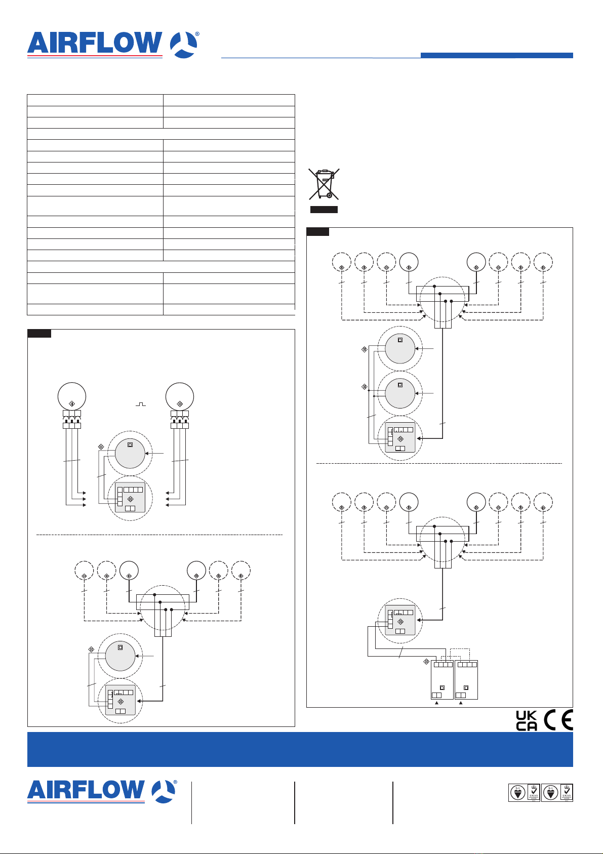
The power supply unit must be connected
according to wiring diagram SD-3 (1 power
supply unit), or SD-4 (2 parallel power
supply units) depending on the conguration.
m Attention!
A ferrite is mounted on the output side of
the power supply unit. This is a component
of the power supply unit and it is required
to ensure correct functionality. The ferrite
must not be removed.
The input and output cables must be installed
so that they are clearly separated from one
another (see Fig. 1). Ideally, position the ferrite
at a distance of approximately 1 cm behind the
power supply unit. Install the cables without
twisting. The cables must not cross each other
and must be shortened accordingly.
All wiring terminals must comply with DIN EN
60998. These terminals must be designed for
a temperature range from 85 °C and a voltage
of 300 V.
Terminal recommendation: Wago Type 221
Fig.1