AIRINNOVATIONS Wine Guardian WG15 Technical Document

1
Wine Cellar Cooling Systems
Through-the-Wall
Wine Cellar CoolingSystems
Installation, Operation and Maintenance Guide
Models: WG15 and WG25
50Hz
Manufactured by:
Syracuse, NY
www.wineguardian.com www.airinnovations.com
Wine Guardian reserves the right, without notice, to make changes to this document at its sole discretion.
Please visit out web site for the most current version of the Wine Guardian manual and other literature.
Wine Guardian is a registered trademark (2,972,262) of Air Innovations, Inc.
Edition 1/2012
© Air Innovations, 2012

2
TABLE OF CONTENTS
Directory of Terms.........................................................................................4
Introduction
...................................................................................................5
Receiving, Inspecting and Unpacking the Wine Guardian System ..............5
Review the Packing Slip to Verify:...............................................................................6
Check the unit for ........................................................................................................6
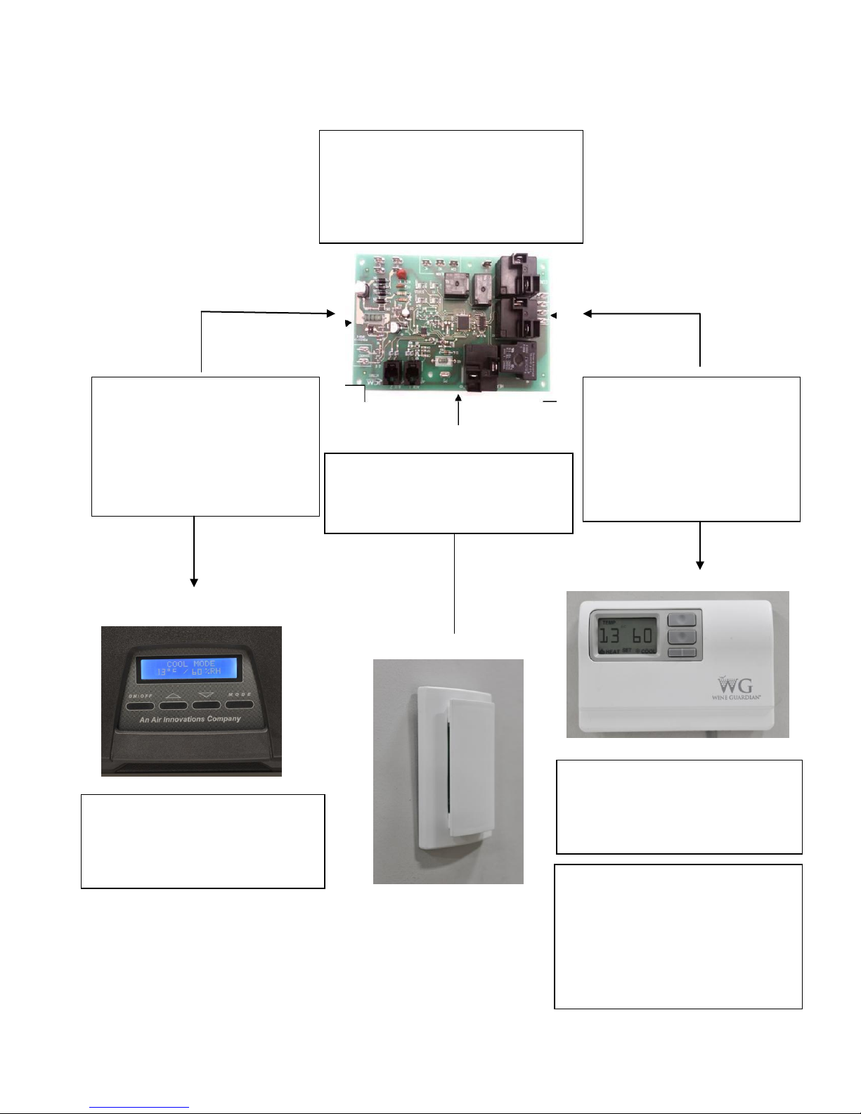
General Description.......................................................................................6
Wine Guardian Controls ..............................................................................................7
Wine Guardian Controls ..............................................................................................8
Standard Specifications
.............................................................................................9
The Wine Guardian System Contains
...................................................................9
Accessories and Optional Equipment
.....................................................................10
Installation Sleeve
.................................................................................................10
Extended
Compressor
Warranty
..........................................................................10
Duct Collar Adapter
..............................................................................................10
Remote Temperature/Humidity Controller
..........................................................10
Remote Temperature/
Humidity
Sensor
...............................................................10
Humidit
y Option.....................................................................................................10
Overview of the Wine Guardian Unit
.......................................................................11
Overview
...................................................................................................................12
Safety ..........................................................................................................13
Safety Message Conventions
..................................................................................13
Danger
...................................................................................................................13
Warning
.................................................................................................................13
Caution
..................................................................................................................13
Lockout/Tagout Procedure
...................................................................................14
Safety Considerations
..........................................................................................14
Safety Hazards
.....................................................................................................14
Electrical Hazards
.................................................................................................14
Electrical Shock Hazards
.....................................................................................14
Hot Parts Haz
a
rds
................................................................................................15
Moving Parts Hazards
..........................................................................................15
Equipment Safety Interlocks
................................................................................15
On/Off Switch.........................................................................................................15
Installation ...................................................................................................17
Pre-installation Test...................................................................................................17
Air Flow Illustration ....................................................................................................17
Planning the Installation.............................................................................................18
Performing a Pre-installation Check
....................................................................19
Locating the System
.............................................................................................19
Power Cord Location
............................................................................................19
Grilles
....................................................................................................................20
Mounting the System
............................................................................................20
Installing the Condensate Overflow...........................................................................22
Installing the Drain Line.............................................................................................22
Priming the Drain Trap
.............................................................................................22

3
Wiring the System for Power
...................................................................................23
Electrical Plug Configuration..................................................................................23
Installing the Thermostat and Communication Cable................................24
Mounting the Optional Remote Interface Controller ...................................24
Installation of the Optional Wine Guardian Remote Sensor......................26
Mounting the Remote Sensor .....................................................................26
Joining Communication Cable ....................................................................28
Changing Jumper Positions (Averaging readings from Remote Sensor)...28
Standard Controller Functions ....................................................................29
Starting-up and Operating the Wine Guardian ...........................................34
Control
Settings ........................................................................................................34
Controller Functions
.............................................................................................34
Regulating the Wine Cellar Temperature
............................................................35
Changing the Air Flow Direction.............................................................................35
Maintenance..............................................................................................357
Maintenance Schedule
............................................................................................36
Monthly
..................................................................................................................36
Yearly
....................................................................................................................36
High Pressure Switch has Shut the System Down
.................................37
Instructions to Reset High Pressure Switch
...........................................................37
Alarm Annunciation................................................................................................37
Troubleshooting...........................................................................................38
Typical Start-up Problems .........................................................................................38
Unit Does not Start-up
.............................................................................................38
Unit is Operating and Blows Evaporator Air, but the Supply Air is not Colder than
the Return Air from the Cellar
..................................................................................39
Problems Controlling Cellar Temperature..................................................................39
Problems Controlling Cellar Humidity
.....................................................................40
Other Miscellaneous Problems..................................................................................41

4
Directory of Terms
Ambient Air –The surrounding area outside the cellar such as a room, basement, garage or
outdoors.
CACLS –Cubic feet per second. A unit of measurement for the amount of air handled by the
fan.
Condensate / Condensation –The water formed out of the air when it is cooled below a certain
temperature (called dew point). Often referred to as “sweating” on pipes and cold surfaces. This
water collects at the bottom of the evaporator or cooling coil and drains out of the unit through
the drain line.
Condenser (Heat Rejection) Section / Coil –The Condenser Section uses the compressor,
condenser coil and fan to remove heat from the refrigerant to the ambient air outside the wine
cellar. The word condenser refers to the condensation of the refrigerant from gas to liquid phase.
CE –Certificate of European conformity
Exhaust Air –The air leaving the evaporator or condenser section of the Wine Guardian unit.
Evaporator (Cooling) Section / Coil –The Evaporator Section uses the cooling coil and the
fan to remove heat from the air inside the wine cellar to the refrigerant, cooling the air and
condensing moisture out of the air. The word evaporator refers to the evaporation of the
refrigerant from liquid to gas phase in the coil. The Evaporator Section is connected to or inside
the wine cellar.
Heat Gain / Loss –The amount of cooling or heating expressed in watts transferred
between the wine cellar and the ambient space. The Wine Guardian must offset this load.
Inlet Air –The air entering the evaporator and condenser sections of the Wine
Guardian unit.
NEC –National Electrical Code
Recovery –The amount of cooling the unit does to return the cellar to its set point
temperature after some new load is introduced, such as people or new cases of warm wine
entering the cellar.
Return Air - The air leaving the cellar and returning to the inlet of the evaporator coil.
SP –Static pressure. Unit of measurement (inches of water column) of the pressure of the air
handled by the fan.
Set Point –The desired temperature or humidity set on the thermostat or humidistat.
Supply Air - The air entering the cellar from the discharge of the evaporator coil.

5
Introduction
Dear Customer,
Congratulations and thank you for purchasing a Wine Guardian cooling system. We believe
it to be the best wine cellar cooling system on the market and hope that you will agree.
This guide is intended to help the installer and owner of the Wine Guardian cooling system
to properly install and maintain the equipment. In order to ensure a long and trouble-free
operation, please read this manual carefully, especially the safety instructions, and keep it
for future reference.
Receiving, Inspecting and Unpacking the Wine
Guardian System
NOTE: Wine Guardian systems are factory assembled and tested prior to
shipment.
Wine Guardian systems are shipped individually in corrugated boxes specially designed to
protect the equipment during shipment.
Before opening the container, inspect the packing crates or boxes for obvious signs
of damage or mishandling.
Write any discrepancy or visual damage on the bill of lading before signing.
Inspect all equipment for any sign of damage caused during transit.
Report all visual or concealed damage to the carrier and file a claim immediately.
WARNING
* DO NOT LIFT THE UNIT UP FROM ITS PLASTIC FRONT PIECES
TO AVOID DAMAGING THEM
**THE UNIT SHOULD BE LIFTED FROM UNDERNEATH ITS BASE AT
BOTH ENDS OF THE SYSTEM.
IMPORTANT
If this procedure is not followed, the shipping company may reject the
claim and the consignee may suffer the loss. Do not return the shipment
to the factory
.

6
Review the Packing Slip to Verify:
Model number
Factory-installed options
System accessories
If any items listed on the packing slip do not match your order information, contact the place
of purchase immediately.
Check the unit for:
An electricalpower cord (factory installed on condenser side)
The Easy Mount™ Through-the-Wall mounting sleeve.
Accessories such ascondenser air duct collar or duct collar kit, and optional controls, if
ordered.
The EasyMount™Through-the-Wall mounting sleeve.
General Description
The Through-the-Wall Wine Guardian cooling system is a professional grade, self-contained
climate control system designed specifically for the storage of wine at cellar temperatures. It is
designed for easy installation and operation. Wine Guardian uses digital electronic controls and
environmentally friendly R-134a refrigerant. All 50Hz Wine Guardian equipment is CE certified.
Each system is factory installed with a sealed, CE-approved power cord and plug that can be
mounted on either end of the cooling system. Wine Guardian products are made in the USA.
The Wine Guardian Through-the-Wall system is completely self-contained and includes an
integral air cooled condenser. The system is functionally divided into two sections, the evaporator
or cooling section, and the condenser or heat rejection section. Each section contains a coil to add
or remove heat and a fan to move the air through the coil and into our or out of the cellar or
adjacent space.
Air from the cellar first enters the cooling coil. Air passes through the cooling coil and is cooled
by the refrigerant inside the coil. This causes any excess humidity in the air to condense and be
captured in the drain pan and internally evaporates as it comes in contact with the integral
condensate removal coil. Air then enters the fan where it is pressured and discharged out of the
system. The thermostat, located on the system, or through the optional remote interface controller,
turns the cooling on and off as needed to maintain its set point.
The compressor and condenser section are activated whenever the system is cooling. The
condenser fan draws air from the surrounding or ambient space. The airflows through the
condenser coil where it absorbs heat from the refrigerant in the coil. The air is finally discharged
out of the system by the condenser fan, and can be ducted outside or to an unused space by an
optional condenser duct kit.

7
CAUTI
ON
THEAIREXHAUSTFORMTHECONDENSERFANISWARMANDCANBE20DEGREESF
ABOVETHEENTERINGAIR TEMPERATURE.
Wine Guardian Controls
Wine Guardian’s digital electronic control series offers a versatile solution for controlling and
monitoring your wine cellar temperature and humidity. This series consists of four controls; a
main control board; a local user interface; a remote user interface; and a remote temperature and
humidity sensor. The system only required the use of the main control board and one of the user
interfaces (local or remote) to function. However, users have the following options to customize
the control capabilities for their application: (See pg. 8 for description of control boards and
optional sensors).
The Wine Guardian’s digital electronic controls are designed to control the operation of the
compressor, condenser fan, evaporator fan, and optional humidifier. There also is pressure switch
monitoring with a dry contact alarm output that will energize in the event of a pressure switch
fault or a high/low temperature or humidity alarm. The local and remote user interface controls
employ user-friendly, menu-driven programming features that can easily be accessed by holding
the mode button on the control for five seconds. Once in the program menu, the user can scroll
through the setting by pressing the mode button and can adjust each setting by using the up and
down arrows. The programming mode allows the user to customize features such as °F or °C
temperature scale, high/low temperature and humidity alarm set points, an adjustable 0-10
minute compressor anti-short cycle delay, sensor averaging options, enable or disable the defrost
feature, an optional keypad lockout code, differential and dead band adjustments, room
temperature calibration, enable or disable the humidifier, and automatic or continuous fan option.
To exit the programming mode the user may either hold the mode button for 5 seconds or the
control will automatically store the settings and exit the programming mode after 10 seconds of
inactivity. Each user interface control will also employ an ON/OFF button that turns the system
on or off respectively.

8
Wine Guardian Controls
Main Control: Performs all switching
functions and interfaces with inputs and
outputs. It can connect to local or remote
user interface, as well as remote
temperature/humidity sensor.
Two way communications: local
user interface reports settings back
to main control, main control
energizes outputs and reports alarms
and temp/humidity readings to local
user interface.
Two way communications: remote
user interface reports settings back
to main control, main control
energizes outputs and reports
alarms and temp/humidity
readings to remote user interface.
One way communication: remote
temp/humidity sensor reports temp and
humidity readings to main control.
Local User Interface: Can be used with
Main Control for adjusting settings,
reading temp/humidity, and reading
fault codes at the unit.
Remote User Interface: Can be with
Main Control for adjusting settings,
reading temp/humidity, and reading
fault codes in a remote location away
from the unit.
Temperature/Humidity Sensor: Can be
used in conjunction with the Main
Control to report temp/humidity from
inside the wine cellar without requiring
a user interface to be located inside the
wine cellar.

9
Standard Specifications
The Wine Guardian System Contains
A capillary tube expansion to control the flow of refrigeration into the evaporator coil
A filter dryer to keep the refrigerant clean and free of contaminants
Dual factory mounted plastic supply/return air grilles for evaporator and condenser air
movement
Movable supply air louvers for side-to-side directing of cold air into the wine cellar
A manually reset, high-pressure switch on the condenser discharge to protect the
compressor from high pressures
Environmentally friendly-134a refrigerant
An internally/externally mounted digital electronic control with many user-controlled
settings
Auxiliary drain port connection at condenser end of unit
All exterior framing of the Wine Guardian is powder coated, 0.063" gauge aluminum to prevent
rust and corrosion. All coils are copper tubes with aluminum fins. The evaporator is coated with
an “E” coat finish to prevent premature corrosion. The system uses an internal drain system to
remove excess moisture and does not reintroduce it back into the cellar. An auxiliary drain port
is located at the condenser end of the unit should there be a need to physically remove the
excessive moisture.
Each system is provided with a pre-wired and tested electronic digital thermostat (local user
interface) as standard, or an optional remote mounted thermostat (remote user interface) in the
wine cellar. The thermostat has multiple control functions for the fan, operation, cooling (if
equipped), and maintaining humidity.
Compressors are self-lubricating, permanently sealed, hermetic reciprocating type compressors,
with internal overload protection and capacity start with a minimum of one-year manufacturer’s
warranty and an optional five-year warranty. Compressors are mounted on rubber-in-shear
isolators to reduce noise and vibration.
Electric power is supplied by a single, factory-furnished cord and plug that can be connected on
the cellar side or the condenser side of the unit. Units are shipped from the factory with a plug
attached on the condenser side. All controls are 24-volt supplied from an internal transformer.
IMPORTANT
Design and specifications are subject to change without notice

10
Accessories and Optional Equipment
Installation Sleeve
Each Wine Guardian system includes an EasyMount™installation sleeve to be used in the
mounting of the system through-the-wall at the desired location. The sleeve is essential for the
proper support of the Wine Guardian system and ease of installation. The maximum dimensions
of the wall opening should be 386mm wide by 413mm high.
For proper operation of the system, including drainage and undue noise and vibration, the
Installation Sleeve must be mounted level within the wall cutout and securely fastened to the
wall studs on either side of the sleeve as shown on page 18.
Extended
Compressor
Warranty
The Wine Guardian uses only the best commercially available compressors on the market.
However, since the compressor is the single most expensive component in the system, it is
recommended that you purchase the extended, five-year warranty option.
Duct Collar Adapter
An optional duct collar kit is available for ease in directing the warm condenser air away from
the through-the-wall unit mounting. The kit includes one (1) duct collar, 15-feet of 6-inches
round flexible ductwork and two (2) tie wraps for connection of the ductwork to the duct collar.
The kit does not include connections at the tie-in point to the remote location or outdoors.
Remote Temperature/Humidity Controller
The remote temperature/humidity controller (Remote Interface Controller) is intended to provide
a means for user interface at a remote location. The controller can be used as a remote
sensor/controller mounted within the wine cellar remote from the Through-the-Wall system. The
controller can also be used as a remote indicator (without sensor) mounted directly outside of the
wine cellar of the residence or building. The Remote Interface Controller includes a backlit face
for temperature and humidity indication along with controller set-up and operational functions.
Remote Temperature/
Humidity
Sensor
The remote temperature/humidity sensor is intended to provide a means of sensing one or more
locations within the wine cellar ands designed to work in conjunction with the Remote Interface
Controller or Local Interface Controller integral to the Wine Guardian Through-the-Wall system.
Multiple sensor readings are averaged and controlled to a single point. The sensors do not have
any temperature or humidity indication and must be mounted within the wine cellar.
Humidit
y Option
An optional stand-alone humidifier comes fully assembled and tested for field installation. It
automatically adds moisture into the cellar by the evaporation of water over a distribution pad.
See page 21-22 for key installation information.
Humidifier Connection: You can locate the low voltage connection for field
optional remote humidifier on side of control panel on the wine cellar side of
the WG cooling unit. The optional humidifier comes pre-wired to fit directly to
this connection for the WG unit to control cellar humidity level desired.

11
Overview of the Wine Guardian Unit
Refer to illustrations on page 10
Cabinet
–
The cabinet is constructed of aluminum with a powder coated finish for corrosion
protection and an attractive, maintenance-free appearance. Areas in contact with cold
temperatures are lined with insulation to prevent condensation.
Condensing Section -
Ambient air is circulated through the condenser section by a direct drive,
permanently lubricated, motorized impeller blower. This section also contains the compressor
and the electrical controls.
EvaporatorSection–
Wine cellar air is circulated through the evaporator section by a direct drive,
permanently or lubricated motorized impeller blower. The large evaporator coil face area
eliminates condensate carry-over, reduces air pressure drop and optimizes heat transfer. A drain
pan is located directly below the coil to capture condensate and is fabricated from aluminum to
prevent rust and corrosion.
Electrical Controls –
All solid state electronic controls are connected internally and/or externally
through a phone cord-type connection. There is no need to open the chassis to access the factory
mounted and wired control. All internal wiring is in accordance with the National Electrical
Code. Wires are numbered and color coded to match the wiring diagrams.
FactoryTested–
All Wine Guardian units are factory run-tested and checked for operational
performance.
Internal Drain
–
Condensate from the evaporator coil is directed to the condensate removal system
at the condenser end of the unit. This allows the drain pan to drain freely. No external trap is
required.
RefrigerantCircuit–
The factory-charged circuit includes a capillary tube expansion device, a filter
dryer, and a manual reset high pressure switch. See Refrigeration Illustration on page 10.
Supply/returngrilles
–
These are made of rugged ABS plastic and factory mounted to automatically
seal to the chassis. Air is introduced through the sides and bottom and discharged through the
front perforated section.
Directional Louvers
–
Two directional louvers are located within the evaporator supply air dis-
charge opening on the Wine Guardian unit and can be accessed by removal of the wine cellar
side faceplate. The louvers are designed to be manually adjusted to direct air flow from side-to-
side or straight on. The louvers can help direct cold air into the center of the wine cellar should
the Through-the-Wall unit be mounted in a corner of the room.

12
Overview

13
Safety
The following is suggested before installing or maintaining the Wine Guardian System:
1)
Read these instructions
2)
Keep these instructions
3)
Heed all warnings
4)
Follow all instructions
Safety Message Conventions
Safety messages contained in this manual, DANGER, WARNING, and CAUTION are bold and
highlighted in red for quick identification.
Danger
A DANGER message indicates an imminently hazardous situation which, if not avoided, results
in death or serious injury. Messages identified by the word DANGER are used sparingly and
only for those situations presenting the most serious hazards.
DANGER
HIGH VOLTAGE - RISK OF SERIOUS INJURY OR DEATH
High voltages are present in the cabinets
TURN OFF ALL POWER BEFORE OPENING PANELS
USE THE LOCKOUT/TAGOUT PROCEDURE
Warning
A WARNING message indicates a potentially hazardous situation which, if not avoided, could
result in death or serious injury.
Following is a typical example of a WARNING message as it could appear in the manual:
WARNING
RISKOFPERSONALINJURYORDAMAGETOEQUIPMENT
Modification to the equipment may cause
injury.
Caution
A CAUTION message indicates a potentially hazardous situation which, if not avoided, could
result in minor or moderate injury. It may also be used to alert against unsafe practices.

14
Following is a typical example of a CAUTION message as it could appear in the manual:
CAUTION
RISK OF PERSONAL INJURY OR DAMAGE TO EQUIPMENT
Improper installation may result in the equipment malfunctioning and a safety hazard. Read all of
the installation instructions before installing the Wine Guardian.
Lockout/Tagout Procedure
1)
Turn the system to off at the local interface controller (the display will
indicate the system is off).
2)
Unplug the unit from the electrical outlet and cover the outlet to prevent
accidently plugging in the system
.
Safety Considerations
The equipment covered by this manual is designed for safe and reliable operation when installed
and operated within its designed specifications. To avoid personal injury or damage to equipment
or property when installing or operating this equipment, it is essential that qualified, experienced
personnel perform these functions using good judgment and safe practices. See the following
cautionary statements.
Installation and maintenance of this equipment is to be performed only by qualified personnel
who are familiar with local codes and regulations, and are experienced with this type of
equipment.
Safety Hazards
Exposure to safety hazards is limited to maintenance personnel working in and around the
system. When performing maintenance, always use the Lockout/Tagout procedure, which is
described in this chapter. Observe the maintenance safety guidelines in the Wine Guardian
manual.
Electrical Hazards
Working on the equipment may involve exposure to dangerously high voltage. Make sure you
are aware of the level of electrical hazard when working on the system. Observe all electrical
warning labels on the system.
Electrical Shock Hazards
All power must be disconnected prior to installation and servicing this equipment. More than
one source of power may be present. Disconnect all power sources to avoid electrocution or
shock injuries.
IMPORTANT
The equipment described in this manual uses electricity. When using this
equipment, be sure to follow the safety procedures outlined in the
Wine Guardian manual.

15
Hot Parts Haz
a
rds
Electric Resistance heating elements (if equipped) must be disconnected prior to servicing.
Electric heaters may start automatically, disconnect all power and control circuits prior to
servicing the system to avoid burns.
Moving Parts Hazards
The Motor and Blower must be disconnected prior to opening access panels. The motor can start
automatically. Disconnect all power and control circuits prior to servicing to avoid serious
injuries or possible dismemberment.
The fans are free-wheeling after the power is disconnected. Allow the fans to stop completely
before servicing the system to avoid cuts or dismemberment.
Rotating Fan Blades are present in the Wine Guardian system. Sticking a hand into an exposed
fan while under power could result in serious injury. Be sure to use the Lockout/Tagout procedure
when working in this area or remove the power cord.
Equipment Safety Interlocks
There are no electrical safety lockouts installed within the system. The power cord attached to the
control box must be disconnected from the power sources prior to working on any part of the
electrical system.
On/Off Switch
To shut down all high volt power internally, the power cord must be removed from power outlet.
Energy
Type Voltage
Hazard ....................................................................Electrocution, electrical burns and shock
Magnitude................................................................................. 230 Vac, 1 phase, 50 cycles
Control Method.................................................... Disconnect power cord and On/Off Switch
DANGER
Never reach into the system while the fan is running.
Avoid risk of fire or electric shock. Do not expose the system to rain or moisture.
WARNING
All supports for the system must be capable of safely supporting the equipment’s weight
and any additional live or dead loads encountered.
All supports for the system must be designed to meet applicable local codes and ordi-
nances.
Do notremove access panels until fan impellers have completely stopped. Pressure
developed by moving impellers can cause excessive force against the access panels.
Fan impellers continue to turn (free-wheel) after the power is shut off.

16
CAUTION
Do not block any supply or return air opening. Install in accordance with the
instructions in the Wine Guardian manual.
Protect the power cord from being walked on or pinched, particularly at the outlet
plug, convenience receptacles, and the point where it exits the system.
Only use attachments/accessories specified by the manufacturer.
Always operate this equipment from a 220/240Vac, 1 phase 50Hz power sources only.
Always ground the outlet to provide adequate protections against voltage surges and
built-up static charges (see Section 810 of the National Electric Code).
Refer all servicing to qualified service personnel. Servicing is required when the
system has been damaged in any way, such as:
Power supply cord or plug is damaged
Liquid has been spilled or objects have fallen into the system
The system has been exposed to rain or moisture
The system does not operate normally
The system has been dropped

17
Installation
CAUTION
SHARP EDGES
RISK OF SERIOUS INJURY
Sharp edges are present inside the Wine Guardian system.
Pre-installation Test
Test the system before installing it to check for non-visible shipping damage.
To test the system:
Set the system on the floor or a sturdy level surface
Plug in the system
Press the on/off switch, control illuminates. This indicates the system has power.
The built in timer prevents short cycling and keeps the system from
turning on right away. The system comes on and runs as long as the
temperature of the space is above the thermostat set point. After several
minutes, cold air comes out of the system from the evaporator section side and
hot air comes from the condenser section. Listen for any unusual noise or
vibration.
Air Flow Illustration
COLD WINE CELLAR
AIR OUT
WARM WINE
CELLAR AIR IN
WARM AMBIENT
AIR OUT
COLD AMBIENT
AIR IN

18
WARNING
RISKOFPERSONALINJURYORDAMAGETOEQUIPMENT
Modification to the equipment may cause injury or damage
to the equipment
.
DANGER
This equipment is heavy. Place the unit on the floor or on a level and stable
surface that can support the full weight of the unit.
Do not modify the equipment, it may cause damage to the equipment and
voids the warranty.
Never place anything on top of the unit.
Never block or cover any of the openings or outlets to the unit.
Never allow anything to rest on or roll over the power cord.
Never place the unit where the power cord is subject to wear or abuse.
Do not use extension cords.
Never overload wall outlets.
Do not remove or open any cover unless the unit is turned off and the power
cord is plugged in.
Use only dedicated power outlet boxes of the correct capacity and
configuration for the unit model.
CAUTION
RISKOFPERSONALINJURYORDAMAGETOEQUIPMENT
Improper installation may result in the equipment malfunctioning and a safety hazard. Read
all of the installation instructions before installing theWine Guardian unit
Planning the Installation
Tools required
Drill/Phillips head Level Stud finder Tape measure Square Drywall screws
Urethane caulk Hand saw Drywall saw Heavy duty
snap knife

19
Where to locate the unit? It can be mounted flush with the racking or flush with
the wall on the wine cellar side.
How to mount the unit? A mounting EasyMount™ kit is supplied.
Locate the electrical power outlet close to the unit, in cellar or out. Do not use
an extension cord!
Factory supplied power cord on condenser side of the unit. It is preferred to be
on the condenser side of the unit, the cord can be moved to accommodate wine
cellar side if need be.
Does the condenser heat exhaust need to be ducted away? An optional kit is
available.
Where to locate the thermostat, if remote interface control is ordered?
Thermostat should be located midpoint on a wall within the wine cellar and
provide sufficient access and exposure to airflow.
How to install the drain line. Run to an open floor drain, container, or
condensate pump.
Are all the parts here to complete the installation? Installation sleeve, gasket,
sealant fasteners
Performing a Pre-installation Check
Check for the properly sized breaker as dictated by the system rating plate data.
Locating the System
Wine Guardian systems are typically installed at the user’s eye level for ease of operation. The
Through-the-Wall system discharges warm air from its condenser end so this should be
considered when determining the location for the system. Locating the system adjacent to a
mechanical room or in close proximity to an exterior wall may be required if ducting the warm
condenser air is being considered. The warmer condenser air can be ducted up to 4.5 meters
away. Be sure to install wire nuts onto the black and white wire leads at the condenser end, once
the cord is removed.
Power Cord Location
As previously noted, the power cord is factory wired on the
condenser side of the system. If you require the cord on the wine
cellar side for plugging into an available outlet, this can be
accomplished by removing the 3-wire leads (ground included) and
moving the cord with connector to the opposite side control bracket
and wire nutting the black and white wires to the factory supplied
leads. The wires must have the terminations cut off and stripped
first. Then screw the ground lead to the hole supplied in the control bracket.
17

20
You must then move the red voltage switch in the opposite direction as from the factory to move
the internal power from the condenser side to the wine cellar side. (See Illustrations)
Grilles
Factory supplied and installed for proper air intake and discharge for optimal system
performance
.
Mounting the System
Follow the steps below for installation of the Wine Guardian Through-the-Wall unit.
Step 1
Find wall stud locations. If both wine cellar side and finished basement
side of walls have drywall already installed it is important to locate the
wall studs in the area chosen to mount the Through-the-Wall system. Use
of any high quality stud finder is recommended for locating the center and
edges of the wall studs on the wine cellar wall. Once located, the stud
edges should be clearly marked prior to following Step 2 below.
Step 2
Preparing wall penetration for Installation Sleeve. Mark the penetration
dimensions on the wall (wine cellar and finished basement side) at the
desired mounting location for the Wine Guardian Through-the-Wall unit.
Keep in mind the ideal height should be at eye level to the user. The unit
controls should be reachable upon installation completion. The wall
penetration should be no more than 368mm wide by 413mm high stud-to-
stud dimension so modifying stud locations is not required.
CAUTION
RISKOFPERSONALINJURYORDAMAGETOEQUIPMENT
Ensure that the area chosen does not have electrical or plumbing interference within the wall
or along the outside of the wall. Failure to do so could cause property damage or personal
injury. If the wall doesinclude electrical wiring or plumbing DO NOT CONTINUE. Contact a
qualified electrician or plumber to relocate these services or choose an alternate location for
mountingtheWGsystem.
Voltage Switch: It is set from factory to supply power to the
line cord wired to condenser side of unit. If you need power
cord moved to wine cellar side of unit, you must move the
switch to the opposite direction from factory setting, which
now will be facing the evaporator side fo the unit (in wine
cellar).
This manual suits for next models
1
Table of contents
Other AIRINNOVATIONS Wine Cooler manuals

AIRINNOVATIONS
AIRINNOVATIONS WINE GUARDIAN DS025 Technical Document

AIRINNOVATIONS
AIRINNOVATIONS WINE GUARDIAN Sentinel Series User manual

AIRINNOVATIONS
AIRINNOVATIONS Wine Guardian D025 User manual

AIRINNOVATIONS
AIRINNOVATIONS WINE GUARDIAN CAB018 Technical Document

AIRINNOVATIONS
AIRINNOVATIONS SENTINEL Series User manual
Popular Wine Cooler manuals by other brands

KooIR
KooIR WineKoolR 120 user guide

Omcan
Omcan JCS-370-A24A instruction manual

Haier
Haier HVZ040ABH5S - Dual-Zone Wine Cooler user manual

La Sommeliere
La Sommeliere SLS117 use instructions

Nordcap
Nordcap W 185 Service manual

Indel Webasto Marine
Indel Webasto Marine Isotherm Divino The One Installation and usage instructions