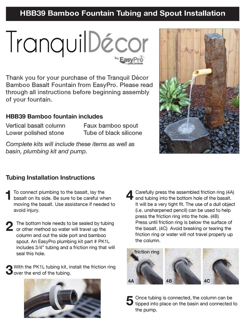
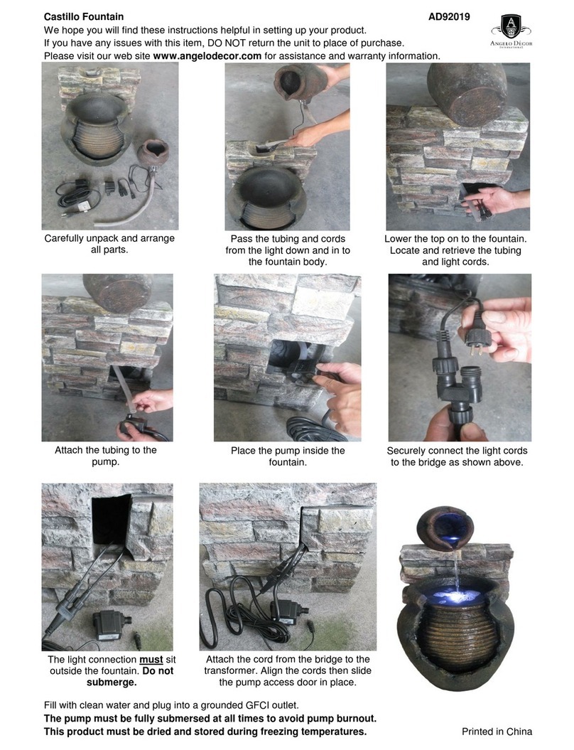
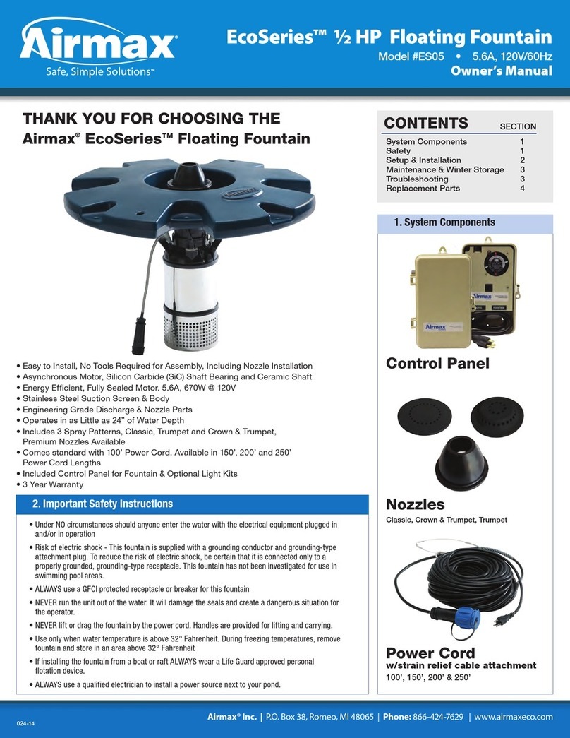
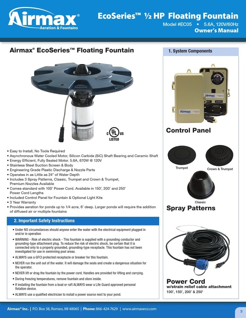
Airmax SolarSeries 654814 User manual

SolarSeries™
Floating Fountain
Owner’s Manual
#654814
Trumpet
Classic
Crown & Trumpet

Airmax, Inc. | 15425Chet'sWay,Armada,MI48005 | Phone: 866-424-7629 | www.airmaxeco.com
THANK YOU FOR CHOOSING
The Airmax®SolarSeries
Floating Fountain
SolarSeries Floating Fountain
OWNER’S MANUAL FOR:
SECTION
TABLE OF CONTENTS
PAGE
1 System Components 3-4
2 Safety 5
3 System Installation 5-15
A.) Tools Required 5
B.) Post Installation 6-7
C.) EasyMount Main 7-9
Assembly Installation
D.) Solar Panel Installation 9-12
& Grounding
E.) Disconnect Switch, 13
Controller, and Fountain
Power Cord Installation
F. ) Fountain Set Up & Installation 14-15
4 Initial Start-Up 15
5 Maintenance & Winter Storage 15
6 Troubleshooting - Fountain 16
7 Replacement Parts 17-18
8 Warranty 19
Trumpet
See Video Instructions of the
Airmax SolarSeries Fountain
Installation Online
2

SolarSeries Floating Fountain
Owner’s Manual
SolarSeries Fountain Components
SolarSeries Solar Panel Components
SolarSeries Power Cord
w/strain relief cable attachment
(Available in 100’– 300’ Lengths)
SolarSeries Fountain
with power unit and float
SolarSeries
Solar Panels (4)
MC4 Cables
(pre-wired leads on back
of each panel)
SolarSeries Fountain
Disconnect Switch &
Controller Assembly
Spray Patterns
(3 Included)
Crown & Trumpet
Trumpet
1. System Components
Classic
(No nozzle required)
3

Airmax EasyMount™ Assembly Components
Grounding Hardware
1. System Components - Continued
1
5
2
6
4
3
1. EasyMount Main Assembly (2)
2. Panel Support Rail Extension
with Hardware (4)
3. Tilt Support Hardware (4)
4. U-Bolts with Hardware (4)
5. Solar Panel Clamp, Single-Sided (8)
6. Solar Panel Clamp, Double-Sided (4)
Grounding Wire
12’ Grounding Wire (2)
8’ Grounding Wire (1)
Grounding Lugs (4) Ground Rod Clamps
1/2” Ground Rod Clamps (4)
Cable Ties (24)
4

2. Important Safety Instructions
3. System Installation
• Read all assembly and operating instructions carefully.
• Under NO circumstances should anyone enter the water with the fountain
plugged in and/or in operation.
• Warning – Risk of electric shock. This fountain is supplied with a grounding
conductor. The fountain has not been approved for use in swimming pool
areas.
• Do not modify the switch or controller wiring.
• Only use Airmax components provided.
• Never run the unit out of the water. It will damage the seals and create a
dangerous situation for the operator.
• NEVER lift or drag the fountain by the power cord.
• During freezing temperatures, remove the fountain and store inside.
• If installing the fountain from a boat or raft, ALWAYS wear a Coast Guard
approved personal floatation device.
• ALWAYS follow instructions provided in the manual for proper installation of
electrical components.
• ALWAYS make sure your hands are dry before performing any maintenance
or troubleshooting of the electrical components.
• Always turn the disconnect switch to the OFF position before removing the
fountain for maintenance or storage.
• ALWAYS wait 48 hours between post installation and solar panel
installation to ensure that concrete is properly cured.
• Avoid installation in windy conditions to prevent damage to solar panels or
mounting hardware.
• Be sure to check for any local underground utilities before digging holes for
solar mounting systems.
• Avoid installation in areas where solar mounting systems could come in
contact with utility poles or wires.
• System must be properly grounded according to the procedure included in
the installation instructions.
• Airmax is not responsible for equipment damage or failure, losses, injury or
death resulting from failure to follow safety precautions, misuse or abuse
of equipment.
GROUNDING: This product must be grounded according to the procedures
outlined in the installation section(s). Grounding reduces the risk of electric
shock by providing an escape wire for the electric current. This product is
supplied with a grounding wire and harnesses with appropriate grounding
features.
WARNING: Check with a qualified electrician or serviceman when
grounding instructions are not completely understood or when in doubt as
to whether the product is properly grounded. Do not modify the grounding
equipment provided with the system.
A) Tools & Hardware Required: (Not included with system)
See Video Instructions of the
Airmax SolarSeries Fountain
Installation Online
TOOLS
• Post Pounder
• Sledge Hammer
• Post hole digger or auger
• Wheelbarrow
• Shovel
• Rake
• Step Ladder
• 1/2" Drill (cordless or electric)
• 1/4" x 6" drill bit
• 5/8" x 6" drill bit
• 3/16" Allen wrench
• 7/16" socket and ratchet
• 7/16" wrench
• 1/2" wrench
• 3/4" deep-well socket and ratchet
• 3/4" wrench
• #2 Phillips screwdriver
• #2 slotted screwdriver
• Tape measure
• Marker or pencil
• 4' level
• Cable cutters
• C-clamps or bar clamps (2 with a minimum 4" throat depth)
• Waders and Coast Guard-approved life jacket
• Compass (or smart phone with compass app)
• Cardboard/blankets/towels to block solar panel energy during installation)
• 10-15 gallons of cold water (bucket or hose)
HARDWARE
• TWO 2-1/2" dia. x 10' (min) Schedule 40 Galvanized Steel Pole
(2.875" O.D. / 2.47" I.D.)
• TWO 1/2" dia. x 8' copper grounding rods
• 4" (I.D.) Schedule 20 PVC pipe (recommended if burying fountain
power cord between solar panels & shore - quantities will vary.
NOTE: Schedule 40 PVC pipe should be used if burying
under a roadway)
• 1/2" dia. x 8" rebar (2) (recommended)
• Concrete bags - 60 lb (10) or 80 lb (8)
• 2 x 4 wooden block (6" - 8" long)
• 2 x 4 x 8' wooden studs for bracing posts during concrete
cure time (4)
• 24" wooden stakes (4)
• 3" wood screws w/ appropriate drill tip (Torx, Phillips, etc)
• Airmax Mooring Kit (recommended)
• Electrical or duct tape
5

3. System Installation - Continued
B) Post Installation
1) Ensure that holes for the solar mounting pole will not interfere with any
underground utilities.
2) Locate the system away from irrigation sprinklers.
3) Select a solar panel mounting location well above the high-water mark of the
pond/lake with optimum southern exposure. Be sure that mounting location
is clear of anything that may obstruct exposure such as trees & shrubbery,
buildings, privacy fences, etc. (Fig 3).
4) Before marking out your two post-hole locations, be sure to establish a plane
that is perpendicular to solar south (Step 4a). Solar south is determined by
the pivot angle needed to achieve optimum southern exposure based on
geographical regions. Establishing this plane will ensure both sets of solar panels
can be installed so that one assembly does not interfere with exposure to the
second solar panel assembly as shown in the overhead view (Fig. 4).
a) Offset from Magnetic South: Often referred to as magnetic declination,
your east/west pivot is determined by the difference between magnetic south
(compass) and solar south (true south/south pole). First, start by using the
National Oceanic and Atmospheric Administration (NOAA) website below to
determine your declination (Fig. 4A).
https://www.ngdc.noaa.gov/geomag/calculators/magcalc.shtml
Simply enter the site zip code in the Location field, click Get & Add Lat/Lon.
Once the information auto-fills, click Calculate to find your declination. Be
sure to note your latitude, as it will be used in a later step.
For example, zip code 48005 (Armada, MI):
Latitude = 42°, Declination = 7° 45’ W.
b) Post Alignment: Lay one of the 10’ galvanized poles on the ground and use
a compass or compass app as a reference to position the pole perpendicular
to magnetic south. Then pivot one end of the post in the appropriate direction
based on your region. The image below (Fig. 4B) uses zip code 48005 as
an example. Here we will pivot 7° west to account for the difference between
magnetic south (compass) and solar south (true south).
c) Post Spacing: Use a post-hole digger or auger to create TWO 10”–12”
diameter holes along the line established in the previous step, 36” deep (min).
This depth should leave you with approximately 84” above grade for your
EasyMount Assembly. The posts should be approximately 76”–80” apart
to leave 8”–10” between each set of solar panels (Fig. 4C). This spacing will
help prevent human traffic that could potentially interfere with solar
panel wiring.
Note: The hole can be bell-shaped at the bottom, but never at the top.
Fig. 3
Fig. 4B
Fig. 4A
Fig. 4C
Fig. 4
Overhead View - Incorrect Overhead View - Correct
Isogonic Lines Show the Pattern of Magnetic Declination
Obstruction Line
Magnetic South
Pole
10 - 12" Holes
Solar South
Pole
Solar South
Winter Production
@ 45º Latitude
50' Tall
Obstruction
Winter Production
@ 30º Latitude
Solar Panels
Solar Panels
80' Clearance Minimum
160' Clearance Minimum
45º
West
45º
East
6

5) Use a 5/8” drill bit to drill a hole through each pole 8”–10” up from the bottom
(it may be helpful to pre-drill a pilot hole with a smaller drill bit first). Insert 1/2”
rebar into each hole so that an equal amount shows out each side. Keep the
rebar in place with electrical tape/duct tape or a zip tie to keep it centered until
post is set. This step is important to keep the post from rotating in the concrete
under high wind conditions. We also advise against use of pre-cut cardboard
tubes inside the holes for the same reason; the use of such tubes can lead to the
entire cylinder of concrete rotating under windy conditions (Fig. 5).
6) Mix concrete and water in wheelbarrow according to the manufacturer's
specifications.
7) Place a post in the center of the first hole and pour concrete into the hole until it
is 4”–6” inches below grade; keeping concrete slightly below grade will prevent
curbing, which can lead to heaving during springtime frost in colder climates.
Repeat for second post.
8) Plumb posts with a level and brace using 2x4 studs, clamps and stakes
(recommended). Allow a minimum of 48 hours’ cure time before installing
the Airmax EasyMount Assemblies and solar panels.
9) Before moving on to the installation of the EasyMount system, drive an 8’
grounding rod into the ground 6”–8” away from the inside edge of the concrete
(Fig. 9), leaving approximately 6” exposed above grade. REPEAT for the second
grounding rod. Grounding wire will be installed later in the grounding section of
the installation procedure.
Note: Grounding rods can be driven below grade after the rest of the system
is installed and properly grounded.
10) If burying the power cord between the solar panels and shoreline, the power
cord should be run in 4" schedule 20 PVC pipe. If burying under a driveway
or roadway, 4" schedule 40 should be used. Conduit should be buried 6”–8”
below grade (Fig. 10). If conduit installation method is not needed,
PROCEED to the next section.
C) EasyMount Main Assembly Installation
1) Using a pencil or permanent marker, mark the post approximately 3” down from
the top on the south side.
2) If installing with one person, we recommend clamping a 2x4 block to the post
at the 3” mark using a large clamp. This block will provide a shoulder/shelf for
the upper beam of the EasyMount Main Assembly to rest on while installing the
U-bolts in Step 3 (Fig. 2).
3) First, rest the EasyMount Main Assembly upper beam on your clamp/block and
secure in place using the two U-bolts, washers, lock washers and nuts. Tighten
one half turn past hand tight using a 3/4" deep-well socket wrench. Secure the
lower pole mount beam with the second U-bolt and tighten one half turn past
hand tight. Leave U-bolts loose enough to pivot the assembly when
re-establishing solar south (Fig. 3).
3. System Installation - Continued
Grounding Rods 6" From Inside Edge of Concrete
Concrete
10 - 12"
8 - 10"
84"
36"
1/2"
Rebar
Fig. 5
Fig. 2
Fig. 3
Fig. 10
Fig. 9
7

Fig. 6A
4) Next, pivot EasyMount Assembly in the desired direction to face solar south,
based on the recommended angle for your region, and tighten all four U-bolts
securely using a 3/4” deep well socket wrench.
Note: This is the same angle established in the previous section during post
hole alignment.
5) Use the latitude of your region to set the optimal tilt angle (Fig. 5). Some smart
phone compass apps will include your latitude and longitude on the screen,
OR you can refer back to the NOAA website from the previous section to find
your latitude.
a) Refer to the table for recommended tilt angle (Fig. 5A).
b) If you will not be running your system in winter months, then simply use
your latitude as your reference point and set your tilt angle to the angle closest
to your latitude (i.e. 42° latitude = 40° tilt angle setting).
c) If you plan to run your system all year, use your latitude and add
between 10º–15º when setting your tilt angle to get optimum performance
when daylight hours are at their shortest. For example, 42° latitude could be
set to the 55° or 60° setting on the EasyMount support rail; this will give
you the optimum tilt angle in winter months when daytime hours are
considerably shorter.
Note: Airmax recommends leaving your tilt angle set for optimum
performance during the winter months when daylight hours are
reduced by nearly 50%. The solar panels will receive ample sunlight in
the other seasons to effectively power the system even when adjusted
for winter operation.
6) Next, remove the tilt support hardware from the temporary location on the
support rail, and attach your tilt support strut to the appropriate hole in the panel
support rail to set your angle. The angles below are based off the difference from
the horizontal plane (Fig. 6A). Secure in place using the tilt support hardware
provided. Tighten completely using two 3/4” wrenches. Repeat for the opposite
side (Fig. 6B).
3. System Installation - Continued
Fig. 6B
Direct Sunlight
Solar Panel
(side view)
45º Tilt20º Tilt
Panel Support Rail
25º
30º
35º
40º
45º
50º
55º
60º
Tilt Support Strut
RECOMMENDED TILT ANGLE
Latitude Tilt Angle Setting
0° to 19° (Vietnam – Thailand) 25° or 30°
20° to 25° (Hawaii – S. Florida) 35° or 40°
26° to 30° (S.Texas – N. Florida) 40° or 45°
31° to 35° (Mid-Texas – N. Georgia) 45° or 50°
36° to 40° (S. Nevada – New Jersey) 50° or 55°
41° to 45° (S. Idaho – Northern Michigan) 55° or 60°
46° to 50° (S. Washington – S. Canada) 60°
51° to 65° (S. Canada - Northern Alaska) 60°
Fig. 5
Fig. 5A
8

7) Continue by installing a panel support rail extension. First, remove the bolts, lock
washers and nuts from the end of the rail extension connector to attach to the
panel support rail. Tighten using one 7/16” wrench and one 7/16” socket wrench
(Fig. 7). Repeat for the opposite side.
8) Lastly, tighten the four pivot bracket bolts using a 3/4” socket wrench (Fig. 8).
9) REPEAT Steps 1–8 for the second post and EasyMount Assembly.
D) Solar Panel Installation & Grounding
CAUTION: To prevent possible injury, cover solar panels with either
cardboard, blankets, or towels to prevent any voltage transmission through
solar panel cables during installation.
Avoid installing solar panels on windy days to prevent possible accidental
damage to equipment.
1) First, position a single-sided solar panel clamp at the bottom edge of one panel
support rail extension and tighten using a 7/16” wrench. Do not tighten the top hex
bolt as you will need room to slip the bottom edge of the solar panel frame into the
clamp (Fig. 1). Repeat for the second panel support rail extension.
2) Temporarily position a double-sided solar panel clamp at the joint between the
support rail and support rail extension; hand tighten only at this time. (Fig. 2).
Repeat for the second panel support rail extension.
3. System Installation - Continued
Fig. 7
Fig. 8
Fig. 2
Fig. 1
9

3) Next, position a single-sided solar panel clamp at the top edge of one panel
support rail and hand tighten only (Fig. 3). Repeat for the second panel support
rail extension.
4) Position the first solar panel so that the wiring junction will face the interior,
ensuring all junction boxes face the solar panels on the adjacent solar post mount
assembly once completed. See orientation in (Fig. 4). Rest one panel on the two
lower single-sided clamps ensuring that the face of the solar panel frame is
beneath the clamp. Hand tighten each clamp.
Note: We recommend using two people when handling and installing
solar panels.
5) Next, loosen the double-sided clamp from the rail on each side. Then position the
clamps so that they seat against the top frame of the solar panel. Secure clamps
to the rail but leave the top hex bolt loose to allow for positioning of the next solar
panel (Fig. 5).
6) Position the second solar panel atop the double-sided clamps, making sure that the
wiring junction box faces the same direction as the lower panel and hand tighten.
Then slide the top two single-sided clamps down until they seat against the top
frame of the upper solar panel. Secure the clamp to the rail with a 7/16” wrench,
but leave the top hex bolts only hand tight (Fig. 6).
3. System Installation - Continued
Fig. 4
Fig. 3
Fig. 5
Fig. 6
10

7) Use your tape measure to center both the upper and lower solar panel widthwise
on the panel support rails. It should measure approximately 17-1/2" from panel
support rail to the edge of the solar panel on each side. Once the panels are
properly centered, secure all clamps using a 7/16” wrench but do not over tighten.
Ensure that you have tightened all bolts securing the clamps to the rail as well as
the upper bolts securing the solar panels in place (Fig. 7).
8) REPEAT Steps 1–7 for second set of solar panels.
Grounding Your System
9) First, attach a grounding lug to the center grounding location of each solar
panel using the screw and nut provided (Fig. 9). Tighten each using a Phillips
screwdriver.
10) Feed one end of the 12’ copper grounding wire through each of the solar panel
grounding lugs and secure using a slotted screwdriver (Fig. 10).
11) Next, slide one ground rod clamp onto the opposite end of the 12' copper
grounding wire. Loosen the bolt on the ground rod lamp, attach it to one of the
upper U-bolts on the EasyMount assembly and secure in place, making sure the
grounding wire is making good contact with the U-bolt. Be sure to leave
some slack in the cable in case the solar panel tilt angle should ever be
changed. (Fig. 11).
3. System Installation - Continued
Fig. 7
Fig. 9
Fig. 10
Fig. 11
11

3. System Installation - Continued
12) Feed the remainder of the grounding cable down the pole and attach in
3–4 places using the cable ties provided (Fig. 12). Be sure to run the grounding
cable down the south side of the pole (facing the solar panels) so that it does not
interfere with installation of the Disconnect Switch and Controller Assembly in
Section E.
13) Next, feed the grounding cable through a ground rod clamp and temporarily
secure in place on top of the grounding rod. Any excess cable can be cut and
discarded, or it can simply be buried alongside the grounding rod.
14) REPEAT Steps 9–13 for the second EasyMount Assembly.
15) Finally, run the 8’ grounding cable from the first to the second grounding rod.
Loosen the ground rod clamp on one ground rod, feed one end of the cable into
the clamp and re-secure to the ground rod. REPEAT for the opposite grounding
rod. (Fig. 15).
Fig. 12
Fig. 15
12

E) Disconnect Switch, Controller, and Fountain
Power Cord Installation
1) Measure down 10"–12" from the bottom beam of the EasyMount Main Assembly
and make a mark on the post. Then, use a 3/16" Allen wrench to remove the 4
bolts holding the controller and disconnect switch mounting brackets together.
Note: The Disconnect Switch & Controller Assembly can be mounted to
either post.
2) Position the top of the disconnect switch mounting bracket at the mark, then attach
the controller mounting bracket to the disconnect switch mounting bracket using
FOUR Allen bolts (Fig. 2A). Secure in place using a 3/16” Allen wrench. When
secured, the switch and controller should be parallel to the solar panels, making
each easily accessible (Fig. 2B).
3) Be sure to leave the switch in the OFF position until after all wiring is complete and
the fountain has been moored in the water.
4) Using MC4 cables and connectors provided, wire the four panels in series based on
the diagram provided (Fig. 4), making sure to connect the negative lead from the
first solar panel to the corresponding connector on the disconnect switch. Next, wire
each subsequent panel so that the wire exits on the + and flows to the – on the
next panel. The + terminal on the last panel will then provide the connection back to
the corresponding connector at the shut-off switch.
Note: Solar panel cables are labeled with + and - symbols. Diagram shows the
control panel on the 'right' pole. Flip wiring if control panel is mounted on the
'left' pole.
5) Use a rope or fish tape to pull the power cord through the pipe, from the shore
to the solar panel mounting pole. Be sure to feed the correct power cord quick
disconnect into the PVC pipe to ensure a proper connection to the controller whip.
6) The power cord disconnect can now be connected to the output side of the
controller whip (Fig. 6).
7) We recommend using a cable tie to secure the power cord to the pole to serve as a
strain relief and prevent any strain on the disconnect.
Recommended Final Grade and Surface Prep: To prevent possible damage to
equipment during lawn maintenance AND to prevent vegetation growth from
obstructing exposure, the immediate areas beneath and around your Airmax
SolarSeries assembly can be prepped with ground fabric and finished with stone
or mulch.
Note: We recommend using the zip ties provided to secure the MC4 cables to
the solar panels. This will help prevent possible wear or chafing to the cable
sheathing during windy conditions.
3. System Installation - Continued
Fig. 4
Fig. 2A
Fig. 2B
Fig. 6
13

Power Cord
Cord Strain
Relief Attachment
Carabiner
Mooring Line
(Vinyl Coated Galvanized Cable)
SolarSeries Fountain
Solar
Panel
Mooring Stake
F) Fountain Set Up & Installation
1) Choose Your Spray Pattern (Fig. 1)
a) The SolarSeries fountain automatically creates the classic pattern without
a nozzle installed. The SolarSeries includes two additional spray patterns
(Trumpet and Crown & Trumpet).
b) To change a pattern, simply unscrew the nozzle nut, replace the pattern
and reinstall the nozzle nut (hand tighten only). We recommend removing
the nozzle nut while displaying the classic pattern.
Note: If you are unable to perform installation of your SolarSeries fountain,
please contact your Certified Airmax Service Technician and they can perform
this installation for you.
2) Assembling the Unit (Fig. 2)
a) Lay the float flat on the ground with Airmax logo facing up. Place the fountain
pump assembly into the center of the float. Lift the float straight up and ensure
that the fountain pump lead power cord passes through the center hole. Gently
lay the fountain to one side.
b) Securely attach the power cord to the fountain pump lead quick disconnect.
Attach the power cord strain relief to the D-ring on the lower intake basket
assembly.
c) Attach a mooring cable (not included) using two outside mounting locations on
opposite sides of the fountain float.
3) Installing the SolarSeries Fountain in Your Pond or Lake (Fig. 3)
a) Pick up the fountain by the float and place it into the water.
Note: A minimum of 36” of water is required for proper operation.
b) Tie one side of the mooring cable to a stake and drive the stake securely
into the ground. Take the other stake and mooring cable and walk around
the pond, carefully pulling the fountain across the water. Once the fountain
is in position, tie the second mooring cable to the second stake and drive it
securely into the ground.
Trumpet Crown & Trumpet
Unscrew Nozzle Nut to
Change Patterns
Fig. 1
3. System Installation - Continued
• 2 stakes
• 2 carabiners
• 2 cable clamps
• 150’, 250’ or 500’ black vinyl
coated galvanized cable
(Mooring Line)
Recommended Mooring Kit
Fig. 3
Mooring Kit Options:
#651052 – 150’ Mooring Kit
#651054 – 250’ Mooring Kit
* Mooring Kit Not Included with Fountain
D-Ring
Fig. 2
14

c) Ensure both mooring cabels are snug to prevent the fountain from twisting
and shifting during operation.
d) Center Mooring Fountain (alternative): To anchor the fountain to the pond floor
using blocks, spread the blocks far enough apart so the mooring lines are
snug and the fountain cannot spin from the force of the motor, which could
cause the lines to become tangled.
e) At this time, after all connections have been made and the system has been
properly grounded, you can test the fountain by turning the disconnect switch
to the ON position.
4. Initial Start-Up
1) Depending on the quality of sunlight, a pattern should slowly emerge from
the fountain.
Note: The Fountain takes approx. 10-15 seconds to start after powering on.
2) The height of each spray pattern will be entirely dependent on the time of day
and the amount of cloud cover that is present. Each spray pattern will reach its
maximum advertised height and width when solar panels are exposed to maximum
sunlight. Fluctuations in pattern size throughout the day are perfectly normal and
should be expected (Fig. 2).
3) If the fountain does not produce a pattern upon initial start-up, refer to the
troubleshooting section in this manual.
5. Maintenance & Winter Storage
1) Maintenance
a) Turn external disconnect switch to the OFF position before attempting
any maintenance.
b) Periodically clean the fountain intake screen of debris, algae, and/or
aquatic weeds.
c) Periodically clean solar panels with a damp, soft cloth. DO NOT use abrasive
sponges or cleaners.
.2) Winter Removal and Storage
a) Remove the fountain from the pond before ice begins to form.
b) Install the winterization cap provided with the power cord quick disconnect.
The power cord can be coiled up either on the shore or in the water near the
pond’s edge after installing the winterization cap. We recommend keeping at
least the disconnect out of the water to avoid damage from shifting ice.
c) Fountain removal is the perfect time to clean or power wash any debris from
the unit before storing.
d) It is recommended to store the fountain and float indoors whenever possible.
3) Spring Installation/Inspection
a) Before reinstalling the fountain in the spring, check the condition of the power
cord and quick disconnect connectors, and replace any o-rings that may be
cracked or missing.
b) Contact your local Airmax Certified Repair Center for annual inspection,
preventative maintenance and cleaning of the fountain motor assembly.
3. System Installation - Continued
Fig. 2
15

6. Troubleshooting
IF FOUNTAIN WILL NOT TURN ON
ISSUE CORRECTION
Not enough sunlight Check when sunlight exposure has improved
Power Cord Cut Repair or replace power cord
Power turned off Turn external disconnect switch to ON
Poor connection at MC4 cables Check all connections between solar
panel cables and disconnect switch
Not enough water in reservoir Bring water level up to at least 36” at fountain
Fountain impeller stuck Remove fountain, clean or replace impeller
Intake plugged Clean intake
IF NOZZLE HAS POOR QUALITY STREAMS
ISSUE CORRECTION
Intake plugged Clean intake
Not enough sunlight Check when sunlight exposure has improved
Debris caught in nozzle holes Remove nozzle, clean, replace
Water coming over the float Check fountain float for water
Spray pattern looks incorrect Check O-Ring on discharge horn assembly
IF FOUNTAIN STARTS AND STOPS
ISSUE CORRECTION
Intake plugged Clean intake
Not enough water in reservoir Bring water level up to minimum depth required
IF STREAMS RAISE AND LOWER
ISSUE CORRECTION
Not enough water in reservoir Bring water level up to minimum depth required
Water coming over the float Check fountain float for water, replace if any
Changes in sunlight conditions None
IF FOUNTAIN IS HUMMING - RUNNING
ISSUE CORRECTION
Normal running None
IF FOUNTAIN IS HUMMING - NOT RUNNING
ISSUE CORRECTION
Intake plugged Clean intake
Voltage not high enough for starting Check when sunlight exposure has improved
Fountain impeller stuck Remove fountain, clean or replace impeller
* If your issue persists or is not covered in the troubleshooting guide above, please contact your Certified Airmax Service Technician to perform any troubleshooting
measures you are uncomfortable with or are unable to perform yourself.
16

7. Replacement Parts & Accessories
1
2
3
4
5
6
7
8
9
11
10
ITEM NO.
PART NUMBER
DESCRIPTION
QTY.
1
653109 - Half HP Intake Basket
Assemblies
1
2
651262-PS_Stainless_Cooling_Shroud-
Half_HP
1
3
652159 - Half HP 230V Pond Series Power
Unit Assy
1
4
653108 - 750 Shaft Stainless Coupler Assy
1
5
651174 SS Shaft-Part-1
1
6
653107 - Thrust Bearing Assy
1
7
653104 - Half HP Impeller and Clip
1
8
651620_lower_shroud_28FEB2015#1-
Part-1
1
9
653103 - Upper Shroud with Bearing Assy
1
10
653102 - Discharge Horn Assy
1
11
653100 - Float Mount Ring Assy,12in
1
12
651500 FLOAT 02-11-13_SMD
1
1/2 HP, 230V
Pond Series Fountain
B
DO NOT SCALE DRAWING
652596- Half HP 230V FNT
SHEET 1 OF 6
5/1/19
MM
UNLESS OTHERWISE SPECIFIED:
SCALE: 1:8
WEIGHT:
REV
DWG. NO.
C
SIZE
TITLE:
NAME
DATE
COMMENTS:
Q.A.
MFG APPR.
ENG APPR.
CHECKED
DRAWN
FINISH
MATERIAL
INTERPRET GEOMETRIC
TOLERANCING PER:
DIMENSIONS ARE IN INCHES
TOLERANCES:
ANGULAR: MACH
1.0 BEND
TWO PLACE DECIMAL
0.010
THREE PLACE DECIMAL
0.005
PROPRIETARY AND CONFIDENTIAL
THE INFORMATION CONTAINED IN THIS
DRAWING IS THE SOLE PROPERTY OF
THE POND GUY INC. ANY
REPRODUCTION IN PART OR AS A WHOLE
WITHOUT THE WRITTEN PERMISSION OF
THE POND GUY INC. IS
PROHIBITED.
A
B
C C
D
4 3
1
1
3
4
5
6
7
8
10
11
12
9
2
SolarSeries Fountain
Replacement Parts
#654815 – Power Unit
1. #653100 – Float Mount Ring Assembly, 12”
2. #652164 – Float Mount Ring Hardware Assembly
3. #653102 – Discharge Horn Assembly
4. #653103 – Upper Shroud with Bearing Assembly
5. #651620 – Lower Shroud, 4”
6. #653105 – Impeller and Clip Assembly, 3/4 – 1 HP
7. #653107 – Thrust Bearing Assembly
8. #653215 – 3/4” Stainless Coated Shaft 1/2 – 5 HP
9. #653213 – Stainless Shaft Coupler Assembly
10. #232561 – Sacrificial Anode
11. #654816 – Motor Assembly
12. #651861 – Stainless Cooling Shroud Assembly,
1/2 –3/4 HP
13. #653209 – Intake Basket Assembly, 3/4 – 1 HP
14. #651500 – Float, 34”, Blue w/Airmax Logo
32" FLOAT
2
1
FLOAT MOUNT RING, 12"
ASSEMBLY
ITEM NO.
PART NUMBER
DESCRIPTION
QTY.
1
651500-R FLOAT 02-11-13_SMD-
Part-1
1
ITEM NO.
PART NUMBER
DESCRIPTION
QTY.
1
651324_FLOAT_MOUNT
_RING-Part-1-1
2
2
94070A540
4
1/2HP POND SERIES
FOUNTAIN
A
DO NOT SCALE DRAWING
652597- Half HP 120V FNT External
SHEET 5 OF 6
UNLESS OTHERWISE SPECIFIED:
SCALE: 1:8
WEIGHT:
REV
DWG. NO.
C
SIZE
TITLE:
NAME
DATE
COMMENTS:
Q.A.
MFG APPR.
ENG APPR.
CHECKED
DRAWN
FINISH
MATERIAL
INTERPRET GEOMETRIC
TOLERANCING PER:
DIMENSIONS ARE IN INCHES
TOLERANCES:
ANGULAR: MACH
1.0 BEND
TWO PLACE DECIMAL
0.010
THREE PLACE DECIMAL
0.005
PROPRIETARY AND CONFIDENTIAL
THE INFORMATION CONTAINED IN THIS
DRAWING IS THE SOLE PROPERTY OF
THE POND GUY INC. ANY
REPRODUCTION IN PART OR AS A WHOLE
WITHOUT THE WRITTEN PERMISSION OF
THE POND GUY INC. IS
PROHIBITED.
A A
B B
C C
D D
4
4
3
3
2
2
1
1
14
1
2
3
4
5
6
7
8
9
11
10
12
13
17

7. Replacement Parts & Accessories - Continued
SEE NOTES
A
DO NOT SCALE DRAWING
_SOLAR FOUNTAIN ASM
SHEET 3 OF 3
UNLESS OTHERWISE SPECIFIED:
SCALE: 1:4
WEIGHT:
REV
DWG. NO.
C
SIZE
TITLE:
NAME
DATE
COMMENTS:
Q.A.
MFG APPR.
ENG APPR.
CHECKED
DRAWN
SEE NOTES
FINISH
MATERIAL
INTERPRET GEOMETRIC
TOLERANCING PER:
ASME Y14.5 - 2018
DIMENSIONS ARE IN INCHES
TOLERANCES:
ANGULAR: MACH
0.1
BEND:
1.0
TWO PLACE DECIMAL:
0.010
THREE PLACE DECIMAL:
0.005
PROPRIETARY AND CONFIDENTIAL
THE INFORMATION CONTAINED IN THIS
DRAWING IS THE SOLE PROPERTY OF
THE POND GUY INC. ANY
REPRODUCTION IN PART OR AS A WHOLE
WITHOUT THE WRITTEN PERMISSION OF
THE POND GUY INC. IS
PROHIBITED.
A A
B B
C C
D D
4
4
3
3
2
2
1
1
THIRD ANGLE PROJECTION
SolarSeries Disconnect Switch
& Controller Assembly
SolarSeries EasyMount
Assembly Replacement Parts
1. #654817 – Fountain Disconnect Switch
&ControllerAssembly Complete
2. #654812 – Replacement Disconnect Switch
3. #654813 – Replacement Fuse for Disconnect Switch
4. #654819 – Fountain Disconnect Switch
&ControllerMountingAssembly
1. #653911 – Solar Panel
2. #654117 – EasyMount Assembly Complete
3. #654116 – EasyMount Post-Mount Assembly
4. #654119 – EasyMount Rail Extension
5. #654126 – EasyMount Support Rail & Support Strut
6. #654127 – EasyMount Single-Sided Clamp (2 pack)
7. #654128 – EasyMount Double-Sided Clamp (2 pack)
1
3
4
2
2
67
5
1
3
4
18

Airmax, Inc.
Airmax SolarSeries Fountain
Limited Warranty
Airmax, Inc. warrants to the original purchaser (the end user) of any Airmax SolarSeries Fountain
manufactured by Airmax, Inc. that any component which proves to be defective in materials or
workmanship, as determined by the factory within 3 years (fountain, electrical components & mounting
hardware) / 25 years* (solar panels) from the original purchased date, will be repaired or replaced at no
charge with a new or remanufactured part, and returned freight prepaid. The end user shall assume all
theresponsibilityandexpenseforremoval,packaging,andfreighttoshiptoAirmax,Inc.todeterminethe
warranty claim andfor allreinstallation expenses.
Thewarrantyisvoidincaseswheredamageresultsfrom:improperinstallation,improperwiring,alteration,
lightning, careless handling, misuse, abuse, disassembly of motor or failure to follow maintenance or
operating instructions.Modication or repairby an unauthorizedrepair facility willvoid the warranty.
In no case will Airmax, Inc. or its dealers accept responsibility for any costs incurred by the user during
installation, removal, inspection, evaluation, repair, parts replacement, or for return freight. Nor will any
liabilitybeacceptedforlossofuse,lossofprots,lossofgoodwill,forconsequentialdamage,orforpersonal
injuriestothepurchaseroranyperson.
In the event of problems believed to be covered under warranty, it will be necessary to notify the dealer
who will try to help resolve the problem and who may contact the factory for additional assistance. If it is
concluded that there may be a defect which may be covered under warranty, it will be necessary to get a
Return Material Authorization (RMA) from the dealer before shipment. Freight collect shipments will not
be accepted bythe factory on warranties or repairs.
The product or part(s) must be returned freight prepaid, to the factory, as directed, and in its original
packaging or in a container which will prevent damage. Parts returned under warranty and damaged
during shipping will not be covered under warranty for the shipping damage. If the factory evaluation of
the returned goods concludes that the failure is due to defects in materials or workmanship, the part or
partsinquestionwillbereplacedunderwarrantywithnewparts,remanufacturedparts,orwillberepaired
at thefactory’s option.Thewarranty period forall parts suppliedunder warranty will terminate at theend
oftheoriginalproduct’swarranty.Allwarrantyshipmentsfromthefactorywillbeshippedfreightprepaid.
Warranty registration isHIGHLY recommended.
No implied warranties of any kind are made by Airmax, Inc. for its products, and no other warranties,
whether expressed or implied, including implied warranties of merchantability and tness for a particular
purpose,shallapply.ShouldanAirmax,Inc.productprovetobedefectiveinmaterialsorworkmanship,the
retail purchaser’s sole remedyshall be repairor replacementof the product as expresslyprovided above.
The manufacturer’s warranty will begin from the dealer’s original purchase date if the product is not
registered.To register a product, you are required to ll out the warranty registration form at airmaxeco.
com/warranty.WarrantyregistrationmustbesubmitteddirectlytoAirmaxwithin30daysoftheend-user’s
purchasedate.
*Degradation ofsolar panels notto exceed 2% inyear one and0.58% annually fromyears 2to 30.
19

Crown &Trumpet Pattern
Optional Double Arch Pattern Optional Double Arch & Geyser Pattern
For Information on Spray Patterns,
Visit Us Online at airmaxeco.com
#652318 V1
Optional Single Arch Pattern
Airmax, Inc.
15425 ChetsWay Street
Armada, MI 48005
(866) 4-AIRMAX
airmaxeco.com
Table of contents
Other Airmax Outdoor Fountain manuals
Popular Outdoor Fountain manuals by other brands

Sunnydaze Decor
Sunnydaze Decor GSI-298 quick guide

Oase
Oase UST 150 operating instructions

Angelo Decor
Angelo Decor AD93121 instructions

Ritchie
Ritchie Thrifty King CT Series installation instructions

Serenity Health
Serenity Health F802 Series quick start guide

Kelkay
Kelkay easyfountain 45067L instructions

Kelkay
Kelkay Easy Fountain 45004L instructions

Ritchie
Ritchie Thrifty King CT Series installation instructions

Campania International
Campania International Navonna Fountain quick start guide

Meet PAT
Meet PAT THE ONE Information booklet

Gainsborough
Gainsborough 11453 Instructions for use

Angelo Decor
Angelo Decor AD93707 quick guide