6
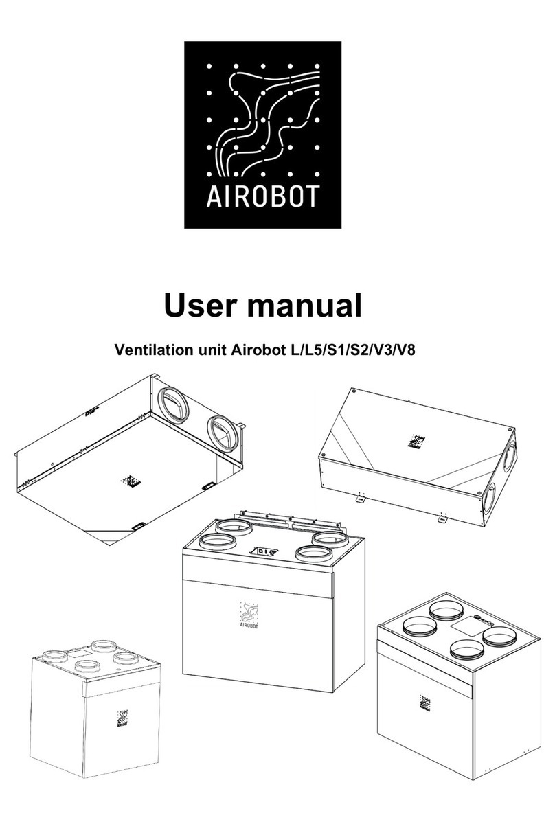
Installing the Airobot S1 / S2
The device must be installed indoors. When selecting a location for your device, note:
●The device shall be installed in the required environmental conditions:
1) The ambient temperature must be between + 5 ° C and + 30 ° C and the humidity up to
80%.
a. The device has 70mm EPS insulation. It is allowed to install the device in an
unheated but dry room (for example, in the attic), but this must be specified with
the dealer when ordering the device. Care must be taken to insulate the
condensate outlet so that it cannot freeze and to use a special heating cable
inside the pipe. The appliance must not be stopped if the ambient temperature is
below 0 ° C, otherwise the appliance may freeze (condensation inside the
appliance).
2) The device does not come into contact with steam or liquids.
●The device makes noise while working and may interfere with life. It is recommended to install
the device in a technical room or other auxiliary room.
●The device must be serviced regularly, so the device must be easily accessible.
Dimensions
Silencers must be installed between the supply,
exhaust and exhaust air ducts and the unit,
otherwise the noise from the fans will reach the
ductwork. When connecting the appliance to the
ventilation duct, make sure that the connections
are properly tightened, airtight and insulated.
Make sure that the insulation covers the fittings
on the appliance, otherwise condensation will
form on the outside of the fittings and damage the
appliance.


