10
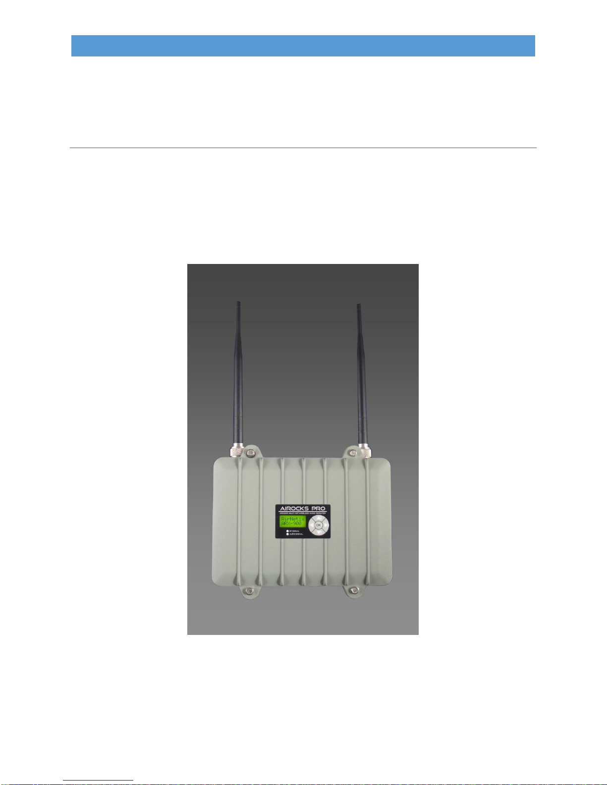
AIROCKS PRO ARX-900 USER GUIDE V1.0
2.5.2 Key Features of the AiRocks Pro System
The AiRocks Pro system is the most feature-rich pro-audio wireless system on the market. These
powerful features give the user a broad array of tools for managing the system in every the most
challenging venues.
2.5.2.1 Multi-Hop Transceiver Architecture
The AiRocks system is the world’s first “multi-hop transceiver” architecture targeting the pro-audio
market. As mentioned earlier, traditional wireless audio systems include separate, inflexible transmitters
and receivers with a transmit range limited by their FCC allowable transmit power. The AiRocks
transceiver architecture gives vastly superior range and coverage of large outdoor venues by virtue of its
“multi-hop” transmission technology.
2.5.2.2 Automatic Link Optimization (ALO)
The AiRocks system includes a novel feature called Automatic Link Optimization (ALO) which
continuously monitors the quality of the link between units (Master->Relay or Relay->Relay) and
automatically selects a new transmission channel if the interference level is too high. If the Packet Error
Rate (PER) of a link exceeds a user-settable limit, the downlink unit will temporarily go off-line, perform
a scan of the local interference environment, determine which of the local channels contains the least
interference, sort the channels by best-to-worst, then send the sorted list of channels to its current
uplink node. If ALO is enabled in the uplink node, the uplink unit will change it transmit channel to one
of the most desirable channel in the list received from the down link node. Thus, if interference appears
after the initial installation has taken place, the links continue to self-optimize to avoid any new or
transient local interference. The entire ALO scan and optimization takes approximately 2 seconds during
which the audio output from the unit is muted.
2.5.2.3 Powerful Network Management System
The AiRocks system includes a powerful Network Management System (NMS) which gives the user a
broad array of tools for monitoring and controlling the network. NMS is built into every ARX-900 unit
and provides a two-way control channel the gives the user a window into the detailed performance of
any remote unit from one central location. Critical functions such as Receive Signal Strength Indicator
(RSSI or receive signal level), Packet Error Rate (PER), Remote Spectrum Analysis (RSA), Audio Level,
Audio Delay, can all be monitored AND controlled from the NMS GUI screen.
2.5.2.4 Network Security
The AiRocks Pro system implements network security through the use of Globally Unique IDs (GUID),
which are similar to MAC addresses in Ethernet network equipment. If the GUID has not been registered
in the NMS database, the unit will not be granted access to the network audio or control information.
2.5.2.5 Automatic or Manual Channel Selection
The AiRocks system is easily deployed by virtue of its automatic transmit and receive channel selection
functions. In the Automatic Channel Selection mode the unit will automatically scan for an uplink
AiRocks transmission. If found the unit will begin receiving the signal and immediately scan its local RF
spectrum for the most desirable downstream channel. Once found, the Relay unit will begin sending the
signal it has received from its uplink source to any downstream units within range. For venues with very
closely spaced AiRocks units (due to speaker placement) a Manual Channel Selection mode is available
which gives the user full control over selection of TX and RX channels.