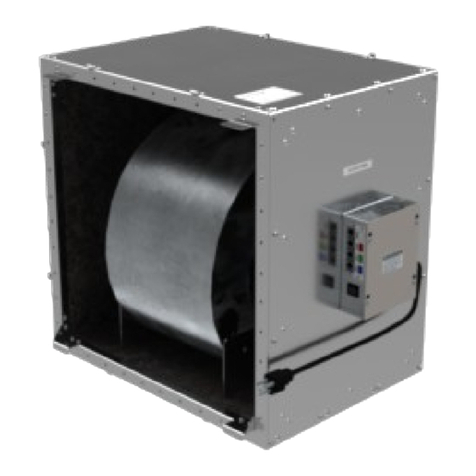
AirScape 3.5E User manual

ORDER # ____________
S/N:___________________
MAC: ____________________
3.5E/3.5E XR AND 4.4E/4.4E XR
WHOLE HOUSE FAN
INSTALLATION AND OPERATION MANUAL
© ALL RIGHTS RESERVED | AIRSCAPE INC.
Congratulations on your AirScape Whole House an purchase. This fan is designed to
provide you with quiet, natural, energy-efficient cooling for many years.
Please take a few minutes to read over this manual to make sure you are prepared for the
installation. The building owner/occupant should read the "Theory of Operation" insert so that
the 3.5e/4.4e WH will be correctly located to maximize effectiveness and efficiency of
operation. Attic venting recommendations and calculations are also included in that insert.
If you (or your installer) have any questions regarding the installation, operation, or
maintenance of this fan, please call 1.866.448.4187 or email e [email protected].
Airscape 3.5e/4.4e WHF I stallatio Ma ual 07/14 Page 1

WHAT’S INCLUDED
Prior to beginning installation, please verify that you received all the accessories with the
whole house fan. The packages should include:
•BOX 1 of 3: damper door enclosure with damper assembly kit, grille, IOM, metal and
wood screws, collar screws, S-hooks, eye bolts and hanging hardware, and the 2nd
Generation Control Package - including 1 hard wired wall control, 1 wall mounting
bracket, and 1 red 50' CAT5 cable.
•BOX 2 of 3: fan assembly, chain, duct tape
•BOX 3 of 3: 20” diameter insulated acoustical flex duct
WHAT YOU WILL NEED
•flat head screwdriver
•scissors or knife
•hammer
•pliers
•cordless screwdriver w/ Philips head and misc drill bits
•lumber matching dimensions of the attic joists
•high quality latex caulk
SAFETY INFORMATION
Not So Obvious - Please Read:
•NEVER operate your whole house fan without a window or door open.
•This fan is meant for general ventilation. It has NOT been designed to vent particle
laden and/or explosive mixtures of air.
•NOT for use in kitchens.
•NEVER force open the damper doors. Always use the yellow clutch releases located on
the actuators before attempting to manually open or close damper doors.
Airscape 3.5e/4.4e WHF I stallatio Ma ual 07/14 Page 2

UNIT PARTS & DIMENSIONS
Parts & Dime sio s
DAMPER BOX ASSEMBLY
The damper box should be assembled before it is moved into the attic. 37 damper screws, 8
plastic rivets, 12 collar screws and 2 inch foil tape are included in the damper assembly kit
that came with your unit.
We recommend installing wireless remotes before putting the unit in the attic – see page 12
All part identification labels (A through E) will be facing the interior of the damper box. Once
assembled, you should not see any of the labels.
Airscape 3.5e/4.4e WHF I stallatio Ma ual 07/14 Page 3

1. Pull out all sections of damper box until you have the base. Set all pieces off to the side
with the label identifying their assembly order facing up. Position base so that the
electrical box and actuators are facing you.
2. Slide both the side panels labeled A into the base as shown. Be sure panels slide into
the locking tabs on the base. The “A” label must be facing the interior of the damper on
both sides.
3. Attach the bottom seams of side panels to the base using the provided screws (5 per
side). Do not over torque. NOTE: We recommended using a manual flat head
screwdriver instead of a cordless screwdriver to avoid over-tightening & stripping.
Airscape 3.5e/4.4e WHF I stallatio Ma ual 07/14 Page 4

4. Slide back panel B onto base, making sure the panel fits securely into the locking tabs
of the base. The B label must face the interior of the unit. The flanges of the side
panels are placed to the inside of the back panel so that they are not seen once the
back panel is in position.
5. Attach the bottom seam of back panel to the base using 5 of the provided screws.
6. Insert 2 plastic rivets along each side seam. Press rivets in by hand, then use a
hammer to completely set each rivet shaft as shown below.
Airscape 3.5e/4.4e WHF I stallatio Ma ual 07/14 Page 5

7. Slide front panel C onto base and into the locking tabs of the base. Make sure the C
label faces inward and the warning and model stickers face outward. The front panel
should sit outside the flanges of the side panel once in position.
8. Insert 2 plastic rivets along each side seam. Use a hammer to set as before. Remove
the electrical box cover and attach the front panel to base using 2 of the provided
screws at pre-drilled holes located inside the electrical box.
9. Using the provided 2 inch wide foil tape, firmly tape along the bottom seam and all 4
side seams on the interior of the unit. Make sure tape is securely attached and will not
interfere with the operation of the damper doors when they open.
Airscape 3.5e/4.4e WHF I stallatio Ma ual 07/14 Page 6

10. Set the top panel D onto the sides on the unit, making sure that the flange sits outside
the side panels and all side panels fit securely into the locking tabs of the top panel.
Attach the top using 20 of the provided screws (5 per side).
11. Place the damper Collar E over the opening on top of the damper and align the screw
holes. Attach the collar using the 12 provided collar screws.
Use the remaining 2 inch foil tape to tape around the outside of the upper seam of the
box and around the base of the damper collar.
Airscape 3.5e/4.4e WHF I stallatio Ma ual 07/14 Page 7

INSTALLATION – CARPENTRY
The 3.5e/4.4e WH has been designed to fit a 22½" x 26½" wall or ceiling opening, which
corresponds to 24” on-center (O/C) framing. With a few extra steps, the 3.5e/4.4e WH can
be installed in situations with 16" O/C framing.
The first step is to construct a simple "box" with inside dimensions of 22½" x 26½". The
3.5e/4.4e WH damper enclosure can be mounted in any orientation, so the following
directions can apply to both ceiling and wall mounting.
For 24" o -ce ter frami g:
The first example below shows the framing using 2x8 joists. The joists are 24" O/C and have
a net space between them of 22½". Two 2x8's, 22½" long have been nailed in place to form
the box. If your joists or trusses are 2x4, 2x6, 2x10, etc., please substitute the appropriate
depth pieces.
For 16" o -ce ter frami g:
The second example below shows the framing using 2x8 joists. The joists are 16" O/C and
have a net space between them of 14½". 2x8's (4 qty @ 14½" long, 1 qty @ 26½" long) have
been nailed in place to form the box. If your joists or trusses are 2x4, 2x6, 2x10, etc., please
substitute the appropriate depth pieces. Note that you will end up with a box with inside
dimensions of 22½" x 26½" with a joist running through it. The "extra" joist will not significantly
disturb the airflow.
Frami g
Airscape 3.5e/4.4e WHF I stallatio Ma ual 07/14 Page 8

Use a stud finder to locate the studs from below or drill pilot holes from above to outline the
grille opening in the drywall ceiling. Cut the opening with a drywall cutter. The opening should
be 22½" x 26½".
Position the 3.5e/4.4e WH damper enclosure on top of the joists. Rotate the enclosure as
required so that there is easy access to the electrical box and so that the damper doors are
centered over the opening (this can be checked from below by depressing the yellow clutch
releases located on the side of the actuators and opening the damper doors manually). The
actuator end of the damper box has two keyholes which are used to attach the damper box to
the joists. Mark the location of the keyholes on the joists by placing the damper box over the
rough opening.
Remove the damper box and fasten two of the provided wood screws so that the screw head
is slightly above the joist. Position damper box over the keyholes and slide to lock into
position.
Use the remaining wood screws to finish attaching the damper box to the joists. or vertical
installations, we advise using longer wood screws than those provided to hold the unit
securely in place.
rom the living area use a good quality latex caulk to seal all wood-to-wood and wood-to-
metal joints to create an airtight enclosure. This is important to ensure that all air drawn in by
the fan will be from inside the house.
Attach the interior grille to the joists with the included white head screws. We advise pre-
drilling these holes. If you have 16" O/C framing, you may need to trim or cut a small section
of the grille flange to accommodate the middle stud.
Grille Notch – 16” O/C I stallatio s ONLY.
Airscape 3.5e/4.4e WHF I stallatio Ma ual 07/14 Page 9

FAN AND DUCT INSTALLATION
Attach provided eye bolts to four locations on attic rafters. The eye bolts should be attached
as close to the center of the width of the rafter as possible.
Attach 4 S-hooks to 4 of the D-rings attached on the fan housing. Hang the fan from the eye
bolts placed on the attic rafters using 4 lengths of the supplied chain. The 4 lengths of chain
are used to support the weight of the fan and to eliminate any swaying motion. Once the fan is
balanced and secure, use pliers to close all S-hooks to ensure stability. Tape down any
unused D-hooks to avoid excess rattling.
Ha gi g the fa
Slide one end of the flexible duct over the damper box collar and fasten with 4 sheet metal
screws (see image below).
Attach the other end of the flexible duct to the fan collar using the remaining sheet metal
screws.
inish by wrapping the damper/duct and fan/duct connections with the provided tape to make
the seams airtight.
The duct should be gently bent 90 degrees for maximum sound attenuation and airflow.
Avoid sharp bends in the duct or contact with metal fixtures, pipes, or conduits. The duct
section immediately before the fan should be as straight as possible to ensure smooth airflow
to the fan. The duct can be supported under the bend if desired using extra chain wrapped
with a protective material.
Airscape 3.5e/4.4e WHF I stallatio Ma ual 07/14 Page 10

Duct to Damper a d Duct to Fa Co ectio s
Fully I stalled View
Airscape 3.5e/4.4e WHF I stallatio Ma ual 07/14 Page 11

INSTALLATION – WIRING
Step 1: Locate the electrical box mounted on the side of the damper box. Look for a series of 5
RJ45 ports on the side of the electrical box with this label:
Step 2: Run the green CAT5 cable from either connector port on the fan mounted electrical box
(it does not matter which one) down to the factory installed fan control adapter connected to the
green AN port.
Step 3: Run the supplied red CAT5 cable down the wall to the desired wall switch location. A
50ft cable is provided. Plug the cable into the red W/S port on the electrical box.
Step 4: Using the provided mounting bracket as a template, trace an outline on the wall where
you want the wall switch located. Cut out the hole for the mounting bracket.
Step 5: Place the mounting bracket in the hole and secure with the locking tabs by tightening
the silver screws.
Step 6: Connect the red CAT5 cable to the back of the wall switch and set the wall switch in
place on the mounting bracket. Secure face plate to the mounting bracket using the attached
white screws.
Step 7: Plug in the two power cords (one from the fan module and one from the damper unit)
into 120-volt outlets with uninterrupted power.
OPTIONAL STEPS:
WEB CONTROL
Visit our blog: blog.airscapefa s.com and type “web control” into the search field.
Email [email protected] or call AirScape at 866-448-4187 for additional questions.
WIRELESS REMOTE
(see remote manual for complete instructions)
Step 1: Plug the blue CAT5 cable into the remote receiver and into the blue RMT port on the
electrical box. Remove the top cover of the receiver.
Step 2: Press and release the black button on the receiver to begin the merge sequence. The
transmission LED on the receiver will illuminate.
Step 3: Press and release any button on the wireless transmitter while the LED is illuminated.
Step 4: Repeat steps 2 and 3 for any additional transmitters.
Airscape 3.5e/4.4e WHF I stallatio Ma ual 07/14 Page 12

Wiri g Diagram
START UP AND OPERATION
•A dedicated circuit is highly recommended. The power requirements of 120 volts, 9 amps
must be taken into account if allocating power from existing electrical circuits.
•Verify that there are two (2) plugs from the unit connected to uninterrupted 120v power.
One from the fan module and one from the damper unit.
•Make sure that all wiring and connections have been made per this manual and acceptable
wiring standards and that no tools or construction debris have been left in, on or around
the 3.5e/4.4e WH .
•Turn the unit ON using the arrow up button on the control. The damper doors will open and
there will be a slight delay before the fan turns on. Once the fan starts running, continue
turning the fan up until it is running at high speed to verify that the unit runs in all speeds.
Allow for a slight delay when changing speeds for the fan to adjust torque. When the fan is
turned off the doors will shut tightly within 60 seconds. Use the arrow up and down buttons
to increase or decrease speed. Both the 4.4e and the 3.5e WH s have 7 speed settings.
•Always turn the fan on using the UP button. Use the up and down arrows to change
between the speeds. Turn the unit on before pressing the timer button. Press the timer
button 1 time for 1 hour, up to 12 times for 12 hour operation. You can vary speeds while
the timer is programmed, but turning the unit off will cancel the remaining time on timer.
•or additional operating tips, maintenance information or troubleshooting tips, please see
the warranty card.
Airscape 3.5e/4.4e WHF I stallatio Ma ual 07/14 Page 13

UNIT SPECIFICATIONS
3.5e WHF
Speed Setti gs: 7
Fa E ergy Co sumptio : 20/40/70/90/180/240/385 watts min-max
Airflow 800/1300/1600/2050/2500/2900/3500 C M min-max
Acoustical: 39 - 51 dBA min-max @ 1 meter
4.4e WHF
Speed setti gs: 7
Fa E ergy Co sumptio : 25/65/120/175/340/440/700 watts min-max
Airflow 1100/1800/2200/2700/3300/3750/4400 C M min-max
Acoustical: 36 - 58 dBA min-max @ 1 meter
Damper Box Size: 28.75” x 25.75” x 16.75” -- L x W x H
Duct Le gth: 7 feet
Duct Diameter: 20”
Rough Ope i g: 22.5” x 26.5”
Grille Outer Dime sio s: 24.5” x 28.5”
Grille Build: Aluminum with cube core center - powder coated white
Electrical: 120 VAC, 60 Hz
I stallatio : Installs easily on 24” O/C joists. Can be installed on 16” O/C joists by
straddling joist.
Co trols: Wall mounted hardwired timer switch, Web interface capable,
Optional wireless remote
I sulatio : R-10 insulated damper doors
XR - R-49 insulated damper doors
Warra ty: 3 year parts warranty. 1 year controls warranty
*Due to our continual product improvement efforts, performance
ratings and specifications are subject to change without notice.
Airscape 3.5e/4.4e WHF I stallatio Ma ual 07/14 Page 14
This manual suits for next models
3
Table of contents
Other AirScape Fan manuals

AirScape
AirScape X9 VENTURA User manual

AirScape
AirScape AH2-CF-1600 User manual

AirScape
AirScape CVK-105 User manual

AirScape
AirScape SAF10R User manual

AirScape
AirScape 2.5 Setup guide

AirScape
AirScape 1.0 User manual

AirScape
AirScape 3200 User manual

AirScape
AirScape ventura 2.7 User manual

AirScape
AirScape 3200 User manual

AirScape
AirScape 3200 User manual