AirScape 3200 User manual

Order#:
S/N:
(Required for Warranty)
3200 Ventura X5
Whole House Fan
Installation and Operation Manual
3200 Ventura Whole House Fan with Gravity Air oor
Thank you for purchasing an AirScape® Whole House Fan.
Your fan has been designed to provide your home with natural, quiet, and energy-efficient cooling for many years.
Please take a few minutes to read over this manual and its accompanying documents to make sure you are
prepared to install the fan.
Before installing this fan, inspect it and all of its parts for any damage that may have been sustained during
shipping. O NOT INSTALL AMAGE EQUIPMENT. If you suspect this fan was damaged during shipping,
contact AirScape technical support by phone at 1.866.448.4187, or email at experts@airscapefans.com.
Whole House Fans are designed to be installed within a home’s attic, which makes them and their sub-
components extremely difficult to access once installed. Test this fan outside of the attic Before in-stalling it.
Connect the fan to its controls and to a power supply, and ensure it operates properly by turning it on and cycling
through its speed settings. If any difficulties are encountered, contact AirScape technical support
at
1.866.448.4187 or by email at experts@airscapefans.com
AirScape 3200 Ventura Whole House Fan Installation and Operation Manual, 05052021
©AirScape, Inc., 2020. All Rights Reser ed. Page 1

THEORY OF OPERATION
As a home heats up during the day, a large amount of heat is retained in its structure and contents. These
materials give off their heat slowly and continue to heat the home’s interior even if the outdoor temperature is
comfortable. Homeowners are then forced to endure either uncomfortable hot indoor temperatures, or the
expense of air conditioning. AirScape® and Ventura® whole house fans resolve this dilemma by exhausting hot
indoor air out of, and drawing cool outdoor air into, the home.
Each of our fans has been designed for quiet and efficient operation. As such, we strongly recommend running
this fan through the night to extract the maximum possible amount of heat from the home. This not only helps
maintain a comfortable indoor temperature, but essentially “pre-cools” the home ahead of the next day’s rise in
temperature, which reduces, or can even eliminate, the need for traditional air conditioning.
Fan Location Guidelines
• Locate this fan in a central location away from windows that will be opened to promote an even replacement
of air throughout the home and thus a greater cooling effect.
• Locate this fan at the highest point possible to exploit natural convection and help exhaust the hottest indoor
air from the home.
• In a two-story home, the ideal location for this fan is typically in the open area at the top of the stairs.
• Avoid locating this fan in a narrow space or over hard flooring as the reflection of sound off of hard surfaces
can amplify its perceived noise.
• We specifically recommend against locating this fan in a bedroom as humans’ perception of noise is far
greater when the surrounding environment is quiet (such as within a bedroom at night).
• Within the attic, locating the fan (within 18 feet) near an electrical outlet or power supply can minimize the
need for additional electrical work.
Required Attic Ventilation
It is critical that the attic be sufficiently ventilated for this fan to operate properly. Without adequate ventilation,
hot air cannot easily escape from the attic, which creates back-pressure that can substantially reduce the fan’s
performance. Specifically, operating this fan in an attic with less net free ventilation area than recommended will
decrease its airflow and energy efficiency.
Whole House Fan
Model
Lift-Lock
or entura
1700
AirScape or
entura
2500
AirScape or
entura
3200
AirScape or
entura
3400
AirScape or
entura
4300
AirScape or
entura
5300
AirScape
D S 5.0
CEC Required
Minimum Net Free
ent Area
2.3 ft24.3 ft24.3 ft24.6 ft25.8 ft27.1 ft27.1 ft2
AirScape
Recommended Net
Free ent Area
4 ft26 ft26 ft27 ft29 ft210 ft210 ft2
AirScape 3200 Ventura Whole House Fan Installation and Operation Manual, 05052021
©AirScape, Inc., 2020. All Rights Reser ed. Page 2

Venting requirements vary by fan. We recommend
a minimum
of 1 square feet of “net free” ventilation area per
500 cfm at a fan’s highest speed. The minimum attic venting requirements for each model of AirScape® and
Ventura® whole house fan is given in the chart at above.
Net free ventilation area can be provided by any combination of gable, eyebrow, roof cap, soffit, or ridge vents, or
any other method of ventilating the attic space.
However, the openings of most vents are partially obstructed by grilles, louvers, and/or screens. A vent’s “net
free” ventilation area is then the surface area of its opening minus the surface area of any grilles, louvers, or
screening covering it. ifferent types of vents have different ratios of net free area to total area.
Manufacturers typically publish their vents’ net free ventilation areas and/or ratios in their products’ specification
documents. If this information is unavailable, a ratio of 50% net free area to total area is usually a good rule of
thumb. The most notable exception to this rule of thumb are ridge vents. The industry standard net free ventilation
area for ridge vents is 13% of the vent’s length in feet. Thus, a ten foot ridge vent would provide 1.3 sq. ft. of net
free ventilation area.
While in our experience most properly constructed homes have adequately ventilated attics, not all do. Because
sufficient ventilation is so critical to this fan’s performance, it is important that the home’s existing ventilation be
verified before it is installed.
Since most attics have multiple vents, often of different types, it is necessary to count each vent, noting its type
and size. Apply the appropriate ratio to the dimensions of each vent to find its net free area, and sum these values
to find the attic’s total ventilation. An example of how these calculations are made is given in the chart below.
Vent Type imensions Total Area Net Free Area
Ratio (“NFA”)
Net Free Ventilation Area
(=Total Area x NFA)
Louver 24" × 24" 24" × 24" ÷ 144* = 4 ft250% 4 ft2 × .50 = 2 ft2
Ridge 10 feet n/a 13% 10 feet × .13 = 1.33 ft2
Round Soffit 10" diameter 3.14 × 5" × 5" ÷ 144* = 0.55 ft250% .55 ft2 × .50 = .28 ft2
* ÷ 144 = to convert inches into feet Total Net Free Ventilation Area: 3.6 ft2
SAFETY INFORMATION
Some of the principles of this product’s safe installation and operation
are not immediately obvious. Read the following safety information
before continuing further:
• Never
operate this fan without a Window or oor opened.
• This fan is meant for general ventilation.
It has NOT been designed to ventilate particle laden and / or explosive mixtures of air.
• This fan is not for use in kitchens.
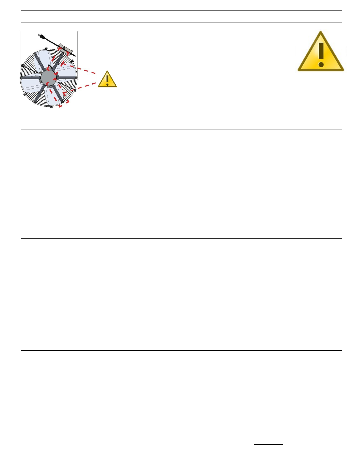
• Never
force open the damper door(s), this could severely damage the actuator.
Always
depress the
actuator’s yellow clutch release before manually opening or closing the damper door(s).
• Before installing or servicing this fan, switch power off at the home’s electrical panel or unplug the fan in the
attic, to reduce the risk of damaging circuit boards, fire, electrical shock, or injury.
AirScape 3200 Ventura Whole House Fan Installation and Operation Manual, 05052021
©AirScape, Inc., 2020. All Rights Reser ed. Page 3

HANDLING INSTRUCTIONS
This fan’s aluminum construction is corrosion-resistant and
extremely durable. However, this fan should NEVER be
handled using any of the Aerodynamic Wings that mount the
motor within the assembly. These Wings are highlighted in the
illustration. Always handle this fan by either its external
casing or the motor itself. You can also handle this fan by its
hanging straps, but be careful as their edges are sharp.
SUPPLIES INCLUDED
Prior to beginning installation, please verify all of the following items were received:
• 20” Fan Assembly. (see last pages for identification of parts)
• oor Assembly (Air- oor 14) (see last pages for identification of parts)
• 20” x 7’ uct Assembly (see last pages for identification of parts)
• Cube-Core Grille (incl. powder-coated wood screws)
• Hardware Kit with square bit driver (incl. Screws / tape / strain relief for interlock)
• igital Touch Controller package—including one igital Touch controller, one wall mounting bracket,
mounting screws and 50 feet of red shielded CAT5 cable.
Once all received parts are verified, perform an operational test BEFORE installing it in the attic.
See pages 9 and 10 for connections to be made.
This is a good time to write down the serial number(s) on this IOM, which will save you a trip to the attic if you
require Tech Support.
REQUIRED TOOLS & SUPPLIES NOT INCLUDED
In addition to the included items listed above, the following tools and supplies are required to install the fan:
• Safety Glasses
• Gloves
• rywall Cutter
• At least 8 wood screws (1½" min. length) and washers sized to fit.
• Cordless screwdriver with Phillips head and miscellaneous drill bits
• High quality caulk
• AirScape MAF (Metal Adjustable Framing 2x4, 2x6, Purchased Seperately) or Lumber matching dimensions of
the attic joists (e.g. 2"x6", 2"x8", etc.) and cut to fit according to the instructions in the Installation section
• Fishing tape or similar tool (to pull control cable through the wall)
ELECTRICAL REQUIREMENTS
The 3200 Ventura model requires a 120 volt, Single Phase, 60 Hz, 15A uninterrupted power supply. These
specifications must be taken into account when allocating power from existing circuits. We strongly recommend
providing a dedicated circuit.
This Circuit
MUST
be Ground Tested.
This can be done easily using a receptacle tester available at most hardware stores.
This fan has a factory-installed, 20 ft. power cord. Consider this length when choosing a location for this fan.
epending on the location of existing outlets in the attic, the installation of an additional outlet may be required.
All wiring and connections must be made according to this manual and acceptable wiring standards. All local
codes must be followed. Consult an electrician if necessary
.
AirScape 3200 Ventura Whole House Fan Installation and Operation Manual, 05052021
©AirScape, Inc., 2020. All Rights Reser ed. Page 4

INSTALLATION OF THE AIR DOOR
Begin by familiarizing yourself with the system. Plan the install in the attic, keeping an eye on the space required
for the components.
Air oor Install Options:
Ceiling or Wall?
AirScape doors can be mounted horizontally or vertically. We recommend installing this fan’s door in the ceiling in
a horizontal orientation, keeping in mind that locating the fan as high as possible helps exhaust the hottest indoor
air from the home. It is wise to check the units placement and fit with the framing
before
cutting the opening.
The Unit can be installed in a wall, however MUST be oriented as shown in Fig. 1
The Air oor 14 (see fig. 1.)
MUST be oriented this way for the gravity doors to function
Note: the angle, not over 40 degrees.
If you choose a wall install we recommend bracing
the underside of the unit with additional framing,
leaving enough room to access the electronics on
the top of the unit.
Fig.1
AirScape 3200 Ventura Whole House Fan Installation and Operation Manual, 05052021
©AirScape, Inc., 2020. All Rights Reser ed. Page 5

Frame in the opening yourself:
Although the design facilitates full install (without having to frame the opening), if this does not work for you, you
can frame the opening yourself.
First, using appropriately sized lumber (e.g. 2" × 6", 2" × 8", etc.) cut to fit, frame in a rough opening from the living
space into the attic as shown below. Make sure framing is installed square on the framing. Cut out the drywall
inside of the framing to create the rough opening. Best method is to drill holes in the inside corners of the created
framing and then saw out the piece from the living space. Clean-up can be made much easier by using a tarp
and/or box to catch the falling debris.
To ensure that all air drawn in by the fan will be from inside the house, use a good quality caulk to seal all wood-to-
wood and wood-to-metal joints to create an air-tight enclosure.
INSTALLING THE GRA ITY AIR DOOR (AD14-22) ASSEMBLY
epending on the configuration
chosen, remove the metal frames
from the Air oor Bottom edge as
needed. (see Image)
Position the Air oor centered
over the opening.
Fasten the unit to the framing
with the included mounting
screws. (8x)
Mounting Screws only need to
“hold” the unit in place, do not
over-tighten which may distort the
door unit.
NOTE: Your Configuration may look different due to installation options
AirScape 3200 Ventura Whole House Fan Installation and Operation Manual, 05052021
©AirScape, Inc., 2020. All Rights Reser ed. Page 6

Mounting Screws
From the living space install the mounting screws
Mounting Screws only need to “hold” the unit in place, do not over-tighten which may distort the door unit.
INSTALLING THE CUBE CORE GRILLE
Place the Grille in the opening
and mark the mounting holes
with a marker.
Pre- rill ALL the Grille mounting
holes.
Install the Grille with the
included screws.
AirScape 3200 Ventura Whole House Fan Installation and Operation Manual, 05052021
©AirScape, Inc., 2020. All Rights Reser ed. Page 7

INSTALLING THE FAN ASSEMBLY
The supplied uct has two ends, one is Conical and the other has a straight Collar. Place the Conical side over the
Fan’s rear edge and secure using the latches mounted on the Fan. Place the Collar side of the uct over the uct
Adapter on top of the Air oor and secure in place using the self-drilling screws as shown.
Routing of the uct and the Support of the bend in the uct influences the performance. A collapsed throat (bend
in the duct) can reduce Airflow substantially. This can be avoided by properly supporting the throat with the
supplied webbing (see image).
Avoid contact between the duct and any metal fixtures, pipes or conduits.
Support the uct under the bend using the provided polypropylene webbing. To fasten the webbing to the attic
joists, fold over the end of the webbing and screw at least two 1½" or longer wood screws include washers
(NOT provided) through multiple layers of webbing and into the joists.
Fan Hanging Straps
Fan Clips (6x)
Conical End
uct
Strap (webbing)
uct Collar
Collar Screws (5x)
(Low Torque Screws)
Put on Gloves and move the fan into the best possible position in your attic and as far away from the Air oor as
possible
while still allowing proper routing.
Note; Face of the Fan MUST remain unobstructed, 24 inch minimum clearance required. Route all wiring away
from the face of the Fan to prevent entanglement
Suspend fan from rafters using hanging strap. Secure hanging strap to rafters using wood screws
(at least 6 x 1½" (minimum length), NOT provided) through the pilot holes on the straps; washers recommended
between screw heads and straps. USE BOTH STRAPS AN KEEP FAN AS LEVEL AS POSSIBLE.
Once the Fan and uct have been hung, seal the joint between the Fan and the uct with the aluminum foil tape
provided. It is acceptable to mount the wiring to the uct with a small piece of tape. If the uct’s Mylar cover was
torn, a piece of tape can be used to seal the tear to seal the duct again.
AirScape 3200 Ventura Whole House Fan Installation and Operation Manual, 05052021
©AirScape, Inc., 2020. All Rights Reser ed. Page 8

INSTALLATION OF THE CONTROLLER
The igital Touch Controller provided with this fan is necessary
for operating it, and must be connected to it regardless of
whether the controller will be installed in a wall.
This fan will not function if not connected to a digital touch controller!
If it is not desired to be installed in a wall, the controller can be connected to the fan and kept in the attic with the
CAT5 cable kept spooled.
Note: you will need a remote to operate it.
The standard control package included with this fan contains 1 wall-mounted igital Touch Controller plus screws;
1 mounting bracket for the controller; and 50 ft. of Red Shielded CAT5 cable.
First, locate the desired location for the igital Touch controller.
Install the mounting bracket according to figures A–C below.
Return to the attic and connect the red CAT5 cable to the RJ45 port on the control box labeled W/S.
Run this cable from the electrical box to the location of the controller.
NOTE: this is a low-voltage cable, O NOT RUN IT PARALLEL TO HIGH-VOLTAGE WIRING; building codes
generally require low-voltage cable to be run through shielded conduit.
NOTE: Carefully unwind and run the CAT5 Cable down the wall,
AVOI kinks as this can damage the Cable conductors!
Connect the CAT5 cable to the RJ45 port on the back of the igital Touch controller.
Mount the controller to the mounting bracket with the provided white screws,
O NOT OVER-TIGHTEN
(figure )
Fig A: Fig. B: Fig. C: Fig. :
Use the mounting Cut out the hole. Place the mounting Connect the CAT5 cable.
bracket as a bracket and secure Mount the face plate to the
template to mark its locking tabs by bracket with the provided
the hole location. tightening the silver screws white screws (see Note 2:)
All wiring connections to the fan assembly are made at the fan-mounted electrical box. These are a 20 ft, black,
factory-installed power cord, and two RJ45 (“Ethernet”) ports for connecting the fan controls and accessories
(see below)
Color Match Cable and Jack Identification
Blue 5 ft CAT5 Ethernet Cable
Connect to RMT and Receiver
20 ft Power Cable Connect to Wall Outlet
RE 50 ft, CAT5 Shielded Ethernet
Cable Connect to W/S and TC
AirScape 3200 Ventura Whole House Fan Installation and Operation Manual, 05052021
©AirScape, Inc., 2020. All Rights Reser ed. Page 9

PURCHASE OPTIONS (not included)
A wireless remote is an available accessory option for this fan. The wireless remote is NOT included as part of this
fan’s standard control package. The yellow manual included with these accessories provides specific instructions
for the installation and operation of the remote.
If purchased
, the wireless remote receiver is connected to the fan-mounted electrical box at the blue RMT RJ45
port. (see Image above)
START-UP AND OPERATION
Before starting this Fan for the first time, verify that:
1. All wiring and connections have been made according to this manual and acceptable wiring standards, and that
this manual and all local codes and standards have been followed in this fan’s installation.
2. No tools or construction debris have been left in, on, or around the fan.
3. The fan’s power cord has been plugged into a ground tested, 120-volt outlet with uninterrupted power.
4. The area in front of the fan’s outlet is as unobstructed as possible, with no object closer than 24” to the face of
the fan.
When running this fan for the first time, make sure to observe it turning on, running at all of its speed settings, and
turning off. Observe from both the attic (to observe the fan(s) itself) and the living space (to observe its damper
door(s)), also verify Timer works at 1 Hour Setting.
As shown, there are four buttons on your fan’s control interface:
When the igital Touch Controller ( TC) is connected to the fan, and the fan to power, a red LE will illuminate.
See the Power Indicator shown above. If the Power Indicator is not illuminated; double-check the connections
between the fan and the controller, between the fan and the power outlet and power at the outlet.
AirScape 3200 Ventura Whole House Fan Installation and Operation Manual, 05052021
©AirScape, Inc., 2020. All Rights Reser ed. Page 10

The AirScape Unit has ten speed settings. Turn on the Fan by touching FAN UP or TIMER UP. The fan will start at
minimum speed. Green LE ’s will illuminate to indicate the speed setting.
Note: there is no delay on a unit with gravity doors.
If the Fan was turned on by TIMER UP, the timer will be set to one hour and blue LE ’s will illuminate to indicate
the timer setting. Press or hold FAN UP to increase the fan’s speed to maximum. Press or hold TIMER UP to
increase the length of time the Fan stays on in one hour increments until the desired time, or the maximum time of
12 hours, is achieved.
If the fan is already operating at minimum speed, touch FAN OWN/OFF to turn off the fan; any time remaining on
the timer will be canceled. If the fan is at maximum speed, press or hold FAN OWN/OFF to decrease the speed to
minimum and once again to turn the fan off.
Press or hold TIMER OWN/CANCEL to reduce the time on the timer by one hour increments until the desired time
is achieved or the timer is canceled. When the timer expires, the fan will turn off automatically. If the timer is
canceled, the fan will remain on at its current speed.
* Note: If untouched after a moment the selection LE ’s will dim.
** Note: If the Fan is on without a timer, the fan will run indefinitely.
OPERATING TIPS
• Never operate your whole house fan without also opening a window or door.
oing so can excessively depressurize your home.
• Only operate your whole house fan when the outdoor air temperature is cooler than the
indoor temperature.
• Make sure your air conditioner and furnace are off before you turn on your whole house
fan. Running either of these together with your whole house fan wastes energy and money
because the fan will force expensively conditioned or heated air out of your home.
• Use your whole house fan’s higher speed settings to cool your home quickly in the evening.
Then, switch to its lower settings to run it quietly and efficiently through the night.
• We recommend you run your whole house fan through the night.
Here’s why: The goal of using a whole house fan is to cool your entire home, not just the air inside it.
Once heated, your home’s structure and contents continue to radiate heat until reaching the
temperature of the surrounding air. By running your fan through the night, you speed up this cooling
process and can then further “pre-cool” your home, reducing or eliminating the need to use air
conditioning the next day. AirScape fans are extremely efficient, so operating your fan in this
way is very inexpensive, especially compared to the cost of air conditioning.
• If your home has a basement, extra cooling can be achieved by drawing in air through the
basement windows.
• You can control where your fan’s cooling effect is concentrated by adjusting the location of
the windows you open. Visualize the path air will travel from the windows to your fan’s opening.
Generally, the longer the path, the more cooling.
AirScape 3200 Ventura Whole House Fan Installation and Operation Manual, 05052021
©AirScape, Inc., 2020. All Rights Reser ed. Page 11

DIGITAL TOUCH CONTROLLER (DTC) CONFIGURATIONS
The function of the igital Touch Controller is dependent on the configuration of the IP switches and
pin jumper located on the back of the PCB. The jumper pins are located to the left of the RJ45 port, and
the IP switches are immediately below it.
The jumper is configured by placing it to connect two of the three pins, as shown. *
The IP switches are configured by switching them to the ON or OFF
position, depending on the switch number. A IP switch in the ON position
is set away from its number, and towards the side labeled ON, as shown.
MODEL JUMPER SETTING DIP SWITCH
SETTING
3200 Sierra (PAL) Pin 1-2*
(time delay**)
3200 entura (AD14-22) Pin 1-2*
(direct start)
*Pin 1-2 = 24V C 80 Hz, PWM Control Signal / Pin 2-3 = 0 – 10 V C Control Signal
** Time delay allows the door(s) to open before the fan starts
Rear View of the
igital Touch Controller
RJ45 Jack
Jumper
ip Switch
AirScape 3200 Ventura Whole House Fan Installation and Operation Manual, 05052021
©AirScape, Inc., 2020. All Rights Reser ed. Page 12

MAINTENANCE
There is no routine maintenance required for the Fan other than making sure the Fan and its damper door(s)
remain clear of dust or debris, and that the area in front of the F an remains as unobstructed as possible, with no
object closer than 24 " to the face of the F an .
A re-settable circuit breaker is located on the Fan-mounted electrical box to protect circuit boards from power
surges. In the case of a power surge, this breaker can be reset by simply pushing the button back in.
TROUBLESHOOTING
Before servicing your whole house fan, turn off power to it at your home’s electrical
panel to reduce the risk of electrical shock, injury, fire, and/or circuit board damage.
Your AirScape Whole House Fan has been factory tested. If you encounter problems with the unit,
please take a few minutes to run through the following troubleshooting procedures
before calling for technical support.
NOTE: a “kinked” CAT5E Cable may cause all of the listed symptoms. Use a second short cable and plug the wall
switch (controller) directly into the W/S port on the fan to rule out a cable issue before proceeding.
Symptom: Unit does not start
Possible causes: No power to unit or kinked Ethernet Cable
Suggestion 1: Is the Red LE on the TC** on? Reset the TC Power (see Start-Up & Operation).
Suggestion 2: Check the re-settable circuit breaker on fan’s electrical box.
Suggestion 3: Take TC into the attic and connect it to the W/S port using another CAT5 Cable.
Suggestion 4: Check power (115VAC) at the electrical outlet, inside the fan’s electrical box wiring at both the
power supply (115VAC) and the SCAB* (24V C inside the fan’s electrical box).
** TC = igital Touch Controller
Symptom: oor(s) does not open, but Fan starts ((PAL) actuated units only).
Possible causes: No power to damper, or damper shaft loose.
Suggestion 1: Operate door(s) manually using the
Actuator Clutch
. Verify that the Actuator rotates with
the door shaft and that the shaft rotates with the door.
Suggestion 2: Check for 24V C at the actuator(s) harness and at the SCAB* (fan’s electrical box)
Symptom: oor(s) open but Fan does not start ((PAL) actuated units only).
Possible causes: Wiring issue between SCAB* and Fan
Suggestion 1: Open Fan’s electrical box and check for power (115VAC) at the fan’s power wires.
Suggestion 2: Check for pwm (control 0-24V C, 80Hz PWM) signal at fan’s control wire connections on the SCAB*.
* SCAB = Simple Controller Attic Board / FAN BOX MOUNTE BOAR
Symptom: Wireless remote does not Operate.
Possible causes: Battery, RF interference.
Suggestion 1: Check transmitter’s battery for power. Replace if necessary.
Suggestion 2: Check to see if LE on the remote receiver in the attic is lit.
Open the cover and see if internal LE ’s respond by pressing a button on the remote.
Suggestion 3: Temporarily replace the CAT5 Ethernet cable.
Suggestion 4: Check for red LE response on TC when pressing the remote buttons.
If problems are encountered, please take a few moments to run through the troubleshooting procedures
described on the blue Warranty Card. If these suggestions do not work, contact AirScape technical support
at
1.866.448.4187 or by email at experts@airscapefans.com for further assistance.
AirScape 3200 Ventura Whole House Fan Installation and Operation Manual, 05052021
©AirScape, Inc., 2020. All Rights Reser ed. Page 13

SPECIFICATIONS – 3200 ENTURA WHOLE HOUSE FAN SYSTEM
imensions Fan: Ø 21.5" × 11" (diameter × depth)
Weight Fan: 25 lbs
Air oor14-22: 14.25” x 22.25” x 11.25” (WxLxH)
Weight A 14-22: 6 lbs
Acoustical uct: Ø 20" x 7 foot long
uct Weight: 11.5 lbs
Tested Airflow*: 9 / 3217 CFM (Low / High)
Tested Power*: 14 / 310 Watts (Low / High)
Tested Noise**: 43 / 60 dBA (Low / High)
Rough Opening: 14.5" × 22.5"
Electrical: 120 VAC, 60 Hz, 15 amps
Installation: 16" or 24" O/C joists
Controls: Low Voltage, igital Touch Controller,
optional wireless remote
Speed Settings: 10
Warranty: 3 years parts; 1 years controls
* Actual performance will vary from installation to installation.
** Tested at 45º and 1 meter from source.
ue to continual product improvement, performance ratings and specifications are subject to change without notice.
NOTES:
AirScape 3200 Ventura Whole House Fan Installation and Operation Manual, 05052021
©AirScape, Inc., 2020. All Rights Reser ed. Page 14

ELECTRICAL SCHEMATIC SIMPLIFIE
AirScape 3200 Ventura Whole House Fan Installation and Operation Manual, 05052021
©AirScape, Inc., 2020. All Rights Reser ed. Page 15
Digital Touch Controller
Optional Remote
Optional Remote
Receiver
Fan Motor
(incl. Wiring)
20 foot Power Cord
120 AC, 60Hz, 1 Phase, 2.5A
Power Supply
120
AC IN,
24DC OUT
FAN BOX BOARD
FAN BOX
24 DC
Motor Control Harness (24 PWM) Optional Blue CAT5E Cable (5ft)
Red CAT5E (Ethernet) Cable
Resetable
Circuit
Breaker
120
AC
EL-204
Shunt/Jumper
(actuator power)
Other manuals for 3200
3
Table of contents
Other AirScape Fan manuals

AirScape
AirScape 3.5E User manual

AirScape
AirScape ventura 2.7 User manual

AirScape
AirScape 2.5E Operating instructions

AirScape
AirScape 3400 VENTURA User manual

AirScape
AirScape CVK-105 User manual

AirScape
AirScape 3200 User manual

AirScape
AirScape 2.5 Setup guide

AirScape
AirScape 3200 User manual

AirScape
AirScape 1.0 User manual

AirScape
AirScape AH2-CF-1600 User manual