AirScape 3200 User manual

ORDER #:
S/N:
(Required for Warranty)
3200
WHOLE HOUSE FAN
INSTALLATION & OPERATION MANUAL
AirScape 3200 Whole House Fans Installation Manual, 03222017
©AirScape, Inc., 2017. All Rights Reserved.
Page 1
Thank you for purchasing this AirScape® whole house fan. Your fan has been designed to
provide your home with natural, quiet, and energy-efcient cooling for many years.
Before installing this fan, inspect it and all of its parts for any damage it may have sustained
during shipping. DO NOT INSTALL DAMAGED EQUIPMENT. If you suspect this fan
has been damaged during shipping, contact AirScape technical support by phone
Whole house fans are installed within a home’s attic, which makes them extremely difcult
to access once installed. TEST THIS FAN AND POWERED AIRLOCK™ OUTSIDE OF
THE ATTIC BEFORE INSTALLING THEM. Connect the fan and Powered AirLock to their
controls and to a power supply, and ensure they operate properly by turning the fan on, cy-
cling through its speed settings, and turning the fan off. If any difculties are encountered,
contact AirScape technical support at the numbers listed above.

SAFETY INFORMATION
• Never operate this fan without a window or door opened.
• This fan is meant for general ventilation. DO NOT USE THIS FAN TO VENTILATE PARTICLE-LADEN
AND/OR EXPLOSIVE MIXTURES OF AIR.
• Do not use this fan for kitchen ventilation.
• NEVER force open the Powered AirLock’s doors as this could severely damage its actuators. ALWAYS use
the yellow clutch releases located on the actuators before attempting to manually open or close
the doors.
• Before installing or servicing this fan, disconnect it from power to reduce the risk of damaging
circuitboards,re,electricalshock,orinjury.
• Install this fan in accordance with this manual and all local codes and standards.
Some of the principles of this product’s safe installation and operation
are not immediately obvious. Read the following safety information
before continuing further:
ELECTRICAL REQUIREMENTS
This fan requires a 120 volt uninterrupted electricity supply. We strongly recommend providing a dedi-
cated circuit for this fan.
This fan has a factory-installed, 10 ft. power cord that originates at the fan-mounted electrical box. Consider this
length when choosing a location for this fan. Depending on the location of existing outlets in the attic, the installation
of an additional outlet may be required.
All wiring and connections must be made according to this manual and acceptable wiring standards. All
local codes must be followed. Consult an electrician if necessary.
This fan’s aluminum construction is corrosion-resistant and extremely durable. However, this fan should never be
handled using any of the aerodynamc brackets that mount the motor within the assembly. These brackets are high-
lighted in the illustration below. Always handle this fan by either its external casing or the motor itself. You can also
handle this fan by its hanging straps, but be careful as their edges are sharp.
HANDLING INSTRUCTIONS
NEVER handle the
fan using any of
these brackets.
AirScape 3200 Whole House Fans Installation Manual, 03222017
©AirScape, Inc., 2017. All Rights Reserved.
Page 2

UNIT PARTS & DIMENSIONS
Fan Assembly Powered AirLock*
Flexible
Acoustic
Duct
*Powered AirLock is shown above as it appears once fully assembled.
AirScape 3200 Whole House Fans Installation Manual, 03222017
©AirScape, Inc., 2017. All Rights Reserved.
Page 3
SUPPLIES INCLUDED IN THE BOX
Prior to beginning installation, please verify all of the following items were recieved:
• Box 1 of 3: Powered AirLock assembly with assembly kit, including base, sides, transition, ¼" nutsetter*, 38 as-
sembly screws*, 6 collar screws*, 4 mounting screws*, and 40 ft. of aluminum tape*; Control package including
Digital Touch Controller*, mounting bracket*, 2 white, at-head controller screws*, and 50 ft. red CAT5 cable*;
White cube-core grille with 8 white wood screws; Installation and Operation Manual, green “Theory of Opera-
tion” insert, and blue “Warranty Card.”
• Box 2 of 3: Fan; 20 ft of aluminum tape; 20 ft. of 1¾" polypropylene webbing.
• Box 3 of 3: 20" diameter exible acoustic duct.
*Astericked items are packaged and shipped within the white "Controls" box within Box 1.
In addition to the included items listed above, the following tools and supplies are required to install the fan:
• Lumber matching dimensions of the attic joists (e.g. 2"× 6", 2"× 8", etc.) and cut to t according to this manual’s
INSTALLATION: FRAMING section, as well as any additional supplies needed to frame the fan’s rough opening.
• Cordless drill with phillips-head screwdriver and miscellaneous drill bits.
• At least 8 wood screws (1½" min. length) and washers sized to t.
• Socket wrench with ¼" and 9/16" sockets or standard wrenches in the same sizes.
• Phillips and at-head manual screwdrivers.
• Drywall Cutter.
• High quality latex caulk.
REQUIRED TOOLS & SUPPLIES NOT INCLUDED
19¼" 29½"
16¼"

INSTALLATION: FRAMING
Using appropriately sized lumber (e.g. 2"× 6", 2"× 8", etc.) cut to t, frame in a rough opening from the living space
into the attic as shown below. Cut out the drywall inside of the framing to create the rough opening.
AirScape 3200 Whole House Fans Installation Manual, 03222017
©AirScape, Inc., 2017. All Rights Reserved.
Page 4
INSTALLATION: POWERED AIRLOCK ASSEMBLY
PARTS
Attach the rst side to the base using 4 of the
provided assembly screws.
Start by placing the base on a at surface.
Find the provided ¼" nutsetter, it can be
used with a cordless drill to assist you in the
next steps (hand tools can also be used).
29½" × 19¼" × 4¾" (L × W × H) 24¾" × 19½" × 4" (L × W × H)

AirScape 3200 Whole House Fans Installation Manual, 03222017
©AirScape, Inc., 2017. All Rights Reserved.
Page 5
INSTALLATION POWERED AIRLOCK ASSEMBLY, cont.
Finish by sealing the seams between the
pieces with the provided aluminum tape at:
1) each corner; 2) around the base; and, 3)
around the transition.
DO NOT OVER-TIGHTEN SCREWS
Attach the next side to the base and to the
rst side using 5 assembly screws.
Once the sides have been fasten to base,
pass the partially-assembled unit into
the attic, without the transition.Pass the
transition into the attic seperately, and then
attach it to the sides using 12 assembly
screws. Attach the mounting brackets to the
base using the last 4 assembly screws.
Attach the remaining sides to base and other
sides using 13 assembly screws at the base
and corners.

AirScape 3200 Whole House Fans Installation Manual, 03222017
©AirScape, Inc., 2017. All Rights Reserved.
Page 6
Connect actuators to fan using factory-
installed, grey MOLEX cable originating
from the fan-mounted electrical box
Connect to fan to power using factory-
installed power cord (10 ft).
Suspend fan from rafters using hanging strap.
Secure hanging strap to rafters using wood screws
(1½" minimum length, NOT provided) through the
pilot holes on strap; washers recommended between
screw heads and straps. USE BOTH SIDES OF
STRAP AND KEEP FAN AS LEVEL AS POSSIBLE.
FAN INSTALLATION
All wiring connections to and from fan are
made at the fan-mounted electrical box.
Face of fan must remain unobstructed; 24-
INCH MINIMUM CLEARANCE REQUIRED.
Route all wiring away from face of fan to
prevent entanglement.
Center Powered AirLock over rough opening and mount it to
framing using the 4 provided mounting screws through the
mounting brackets (if your home's framing is 24" on-center) or
through the ange (if your home's framing is 16" on-center).
Use latches to fasten ductwork to fan.
Once the fan, ductwork, and Powered AirLock have been
successfully connected, seal these seams with the provided
aluminum tape.

AirScape 3200 Whole House Fans Installation Manual, 03222017
©AirScape, Inc., 2017. All Rights Reserved.
Page 7
Controller must be connected to fan
for unit to function, even if it is not
ultimately installed in a wall.
Use red CAT5e cable (50 ft) to connect Digital
Touch Controller to fan. NOTE: this cable is low
voltage, DO NOT run it parallel to to high-voltage
wiring; building codes generally require low-voltage
cables to be run through shielded conduit.
Once the fan has been hung and the ductwork attached
thereto, slide the collared end of the duct over the collar on
the Powered AirLock’s transition. Use the provided ¼" nut-
setter and a cordless drill to fasten the two collars together
using the 6 provided collar screws.
Once the fan, ductwork, and Powered AirLock have been
successfully connected, Finish by sealing this seam with
provided aluminum tape.
Support the ductwork under the bend using the provided poly-
propylene webbing. To fasten the webbing to the attic joists, fold
over the end of the webbing and screw at least two 1½" or longer
wood screws (NOT provided) through both layers of webbing and
into the joists.
Maintain ductwork’s 20" diameter throughout bend, keep the section of duct
immediately prior to the fan as straight as possible, and avoid contact with
any metal xture, pipes, or conduits.
FAN INSTALLATION

INSTALLATION: WIRING & CONTROLS
The standard control package included with this fan contains 1 wall-mounted Digital Touch Controller; 1 mounting
bracket for the controller; and 50 ft. of red CAT5 cable.
All wiring connections to the fan assembly are made at the fan-mounted electrical box. These include: a 10 ft, black,
factory-installed power cord; a 9 ft, grey, factory-installed MOLEX cord for connecting the Powered AirLock’s actua-
tors to the fan; and three RJ45 (“ethernet”) ports for connecting the fans controls and accessories, labled as follows:
The Digital Touch Controller provided with this fan is necessary for operating it, and
must be connected to it regardless of whether the controller will be installed in a
wall. THIS FAN WILL NOT FUNCTION IF NOT CONNECTED TO A DIGITAL
TOUCH CONTROLLER! If it is not desired to be installed in a wall, the controller
can be connected to the fan and kept in the attic with the CAT5 cable kept spooled.
AirScape 3200 Whole House Fans Installation Manual, 03222017
©AirScape, Inc., 2017. All Rights Reserved.
Page 8
First, locate the desired location for the Digital Touch Controller. Install the mounting bracket according to Figures
A–C below.
Return to the attic and connect the red CAT5 cable to the RJ45 port on the fan electrical box labled W/S. Run
this cable from the electrical box to the location of the controller. NOTE: this is a low-voltage cable, DO NOT RUN
IT PARALLEL TO HIGH-VOLTAGE WIRING; building codes generally require low-voltage cable to be run through
shielded conduit.
Connect the CAT5 cable to the RJ45 port on the back of the Digital Touch Controller. Mount the controller’s face-
plate to the mounting bracket with the provided white screws, as shown above in Figure D.
Next, connect the MOLEX cord from the fan-mounted electical box to the MOLEX cord from the Powered AirLock’s
actuators. Finish by plugging the power cord into an outlet with uninterrupted 120-volt power.
Use the mounting
bracket as a template to
mark the hole location.
Figure A
Cut out the hole. Place the mounting bracket
and secure its locking tabs
by tightening the silver
screws
Figure B Figure C Figure D
Connect the CAT5 cable.
Mount the faceplate to the
bracket with the provided
white screws
INSTALLATION: GRILLE
The cube-core grille is installed from within the living space after the fan, duct, and Powered AirLock have been in-
stalled in their nal location within the attic. Before mounting the grille, use a high-quality latex caulk to seal all wood-
to-wood and wood-to-metal seams within the space formed by the Powered AirLock and framing.
Next, mount the grille to the framing using the eight white wood screws provided. We strongly recommend pre-
drilling holes in the framing for these screws; be careful to prevent them from stripping.

AirScape 3200 Whole House Fans Installation Manual, 03222017
©AirScape, Inc., 2017. All Rights Reserved.
Page 9
START-UP & OPERATION
Before starting this fan for the rst time, verify that:
1. All wiring and connections have been made according to this manual and acceptable wiring standards, and that
this manual and all local codes and standards have been followed in this fan’s installation;
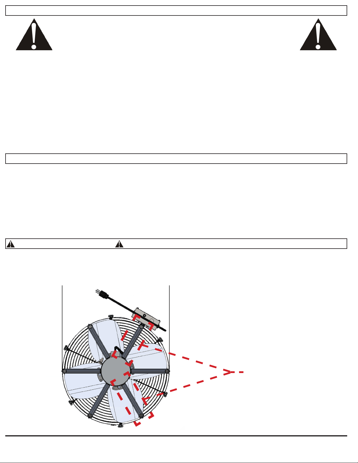
2. No tools or construction debris have been left in, on, or around the fan;
3. The fan’s power cord has been plugged into a 120-volt outlet with uninterupted power; and,
4. The area in front of the fan is as unobstructed as possible, with no object closer than 24” to the face of the fan.
Whenrunningthisfanforthersttime,makesuretoobserveitturningon,runningateachofitsspeed
settings, and turning off from both the attic (to observe the fan itself) and the living space (to observe the
Powered AirLock’s doors).
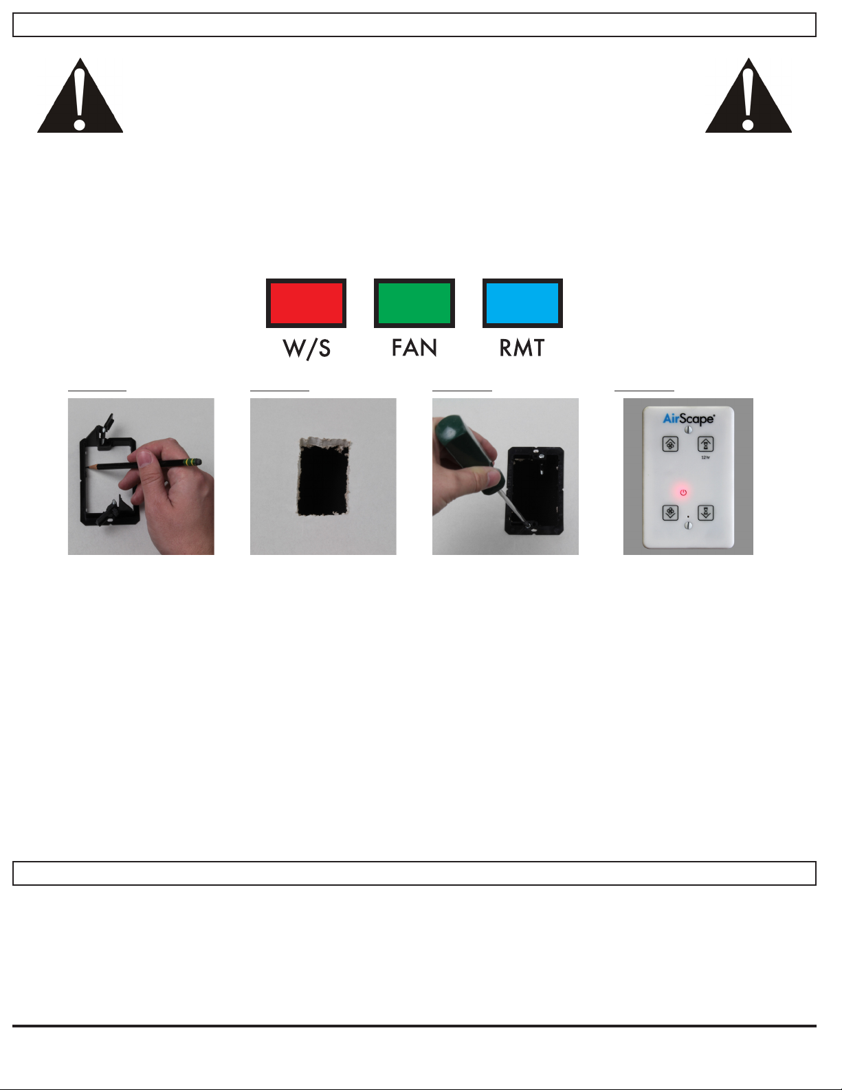
As shown below, there are four buttons on your fan’s control interface:
When the Digital Touch Controller is connected to the fan, and the fan to power, a red LED will illuminate beneath
the Power Indicator shown above. If the Power Indicator is not illuminated, double-check the connections between
the fan and the controller, and between the fan and the power outlet.
Turn on the fan by touching FAN UP or TIMER UP. The Powered AirLock’s doors will open and there will be a 10
second delay before the fan begins to operate. The fan will start at minimum speed. Green LEDs will illuminate to
indicate the speed setting. If the fan was turned on by TIMER UP, the timer will be set to one hour and blue LEDs
will illuminate to indicate the timer setting.
Press or hold FAN UP to increase the speed incrementally until reaching the desired or maximum speed. Press or
hold TIMER UP to increase the time on the timer in one hour increments until the desired time, or the maximum time
of 12 hours, is achieved.
If the fan is already operating at minimum speed, touch FAN DOWN/OFF to turn off the fan; any time remaing
on the timer will be canceled. If the fan is at any higher speed, press or hold FAN DOWN/OFF to incrementally
decrease the speed until reaching the desired speed or turning the fan off.
Press or hold TIMER DOWN/CANCEL to reduce the time on the timer in one hour increments until the desired
time is achieved or the timer is canceled. If the timer is canceled, the fan will remain on at its current speed. If the
timer expires, the fan will turn off.
Whenever the fan is turned off, the Powered AirLock’s doors will close tightly within about 60 seconds.
FAN UP
FAN DOWN
/OFF
TIMER DOWN/
CANCEL
TIMER UP
Power Indicator

MAINTENANCE, TROUBLESHOOTING, TECHNICAL SUPPORT
There is no routine maintenance required for this fan other than making sure the fan and Powered AirLock remain
clear of dust or debris, and that the area in front of the fan remains as unobstructed as possible, with no object
closer than 24" to the face of the fan.
A resettable circuit breaker is located on the fan-mounted electrical box to protect circuit boards from power surges.
In the case of a power surge, this breaker can be reset by simply pushing the button back in.
If problems are encountered, please take a few moments to run through the troubleshooting procedures
described on the blue Warranty Card. If these suggestions do not work, contact AirScape technical sup-
WIRELESS REMOTE (NOT INCLUDED)
A wireless remote is an available accessory for this fan. It is not included as part of this fan’s standard control pack-
age. The yellow manual included with the remote provides specic instructions for this accessory’s installation and
operartion. Briey, the steps for installing the remote are as follows:
• Remove the top cover of the remote receiver. Plug the provided blue CAT5 cable into the remote receiver
and into the blue RMT port on the fan-mounted electrical box.
• Press and release the black button (labled “LEARN”) on the receiver’s circuit board to begin the merge
sequence; the transmission LED on the receiver will illuminate.
• Press and release any button on the wireless transmitter while the transmission LED on the reciever is
illuminated. Unplug the CAT5 cable from the receiver, replace its cover, and then replug the CAT5 cable
into the reciever.
AirScape 3200 Whole House Fans Installation Manual, 03222017
©AirScape, Inc., 2017. All Rights Reserved.
Page 10

SPECIFICATIONS*
Speed Setting: 1 2 3 4 5 6 7 8 9 10
3200
Airow (CFM): 723 1388 1853 2212 2532 2834 3075 3123 3178 3253
Power (watts): 18 42 75 116 162 215 272 287 304 321
Efciency (watts/CFM): 40.2 33.0 24.7 19.1 15.6 13.2 11.3 10.9 10.5 10.1
Noise (dBA):
Rough Opening Dimensions: 14.5" × 22.5"
Grille Outer Dimensions: 16" × 24"
Grille Build: Cube Core, Aluminum, White Powder Coat
Powered AirLock Dimensions: 23.25" × 15.75" × 16.25" (L x W x H)
Duct Length: 7 ft.
Duct Diameter: 20"
Electrical: 120VAC, 60 Hz, 15 amps
Insulation: R-10; R-49 in “-XR” models
Controls: Low Voltage; Hardwired Wall Switch, Optional Wireless Remote
Installation: Installs easily on 24" or 16" O/C framing
Warranty: 3 years
*Actual performance will vary from installation to installation. Due to our continual product improvement efforts, performance ratings and
specications are subject to change without notice.
AirScape 3200 Whole House Fans Installation Manual, 03222017
©AirScape, Inc., 2017. All Rights Reserved.
Page 11
2ND GENERATION CONTROLS UPGRADE (NOT INCLUDED)
AirScape's "2nd Generation Control Package" is an available accessory for this fan. It is not included as part of this
fan’s standard controls. The 2nd Gen. Controls include a webserver that allows you to operate your fan from any
smartphone, tablet, or computer with access to your home's local area network ("LAN"). They are also necessary to
use AirScape's Temperature Sensor Package ("TSP") and SafeSpeed™ Pressure Interlock accessories.
The manual included with the 2nd Generation Controls provides specic instructions for there installation and op-
eration. If purchased, the 2nd Gen. Controls are connected using the green FAN RJ45 port on the fan-mounted
electrical box.

AirScape 3200 Whole House Fans Installation Manual, 03222017
©AirScape, Inc., 2017. All Rights Reserved.
Page 12
INSTALLATION NOTES
Other manuals for 3200
3
Table of contents
Other AirScape Fan manuals

AirScape
AirScape 2.5E Operating instructions

AirScape
AirScape 3200 User manual

AirScape
AirScape 2.5 Setup guide

AirScape
AirScape ventura 2.7 User manual

AirScape
AirScape 1.0 User manual

AirScape
AirScape AH2-CF-1600 User manual

AirScape
AirScape 3200 User manual

AirScape
AirScape 3.5E User manual

AirScape
AirScape 3200 User manual

AirScape
AirScape SAF10R User manual