AirScape 2.5E Operating instructions

ORDER #:
S/N:
MAC:
(Required for Warranty)
2.5e & 2.5eXR
WHOLE HOUSE FAN
INSTALLATION AND OPERATION MANUAL
AirScape 2.5e Whole House Fan Installation Manual, 03152016
©AirScape, Inc., 2016. All Rights Reserved.
Page 1
Thank you for purchasing an AirScape® whole house fan. Your fan has been designed to provide your
home with natural, quiet, and energy-efcient cooling for many years.
Please take a few minutes to read over this manual and its accompanying documents to make sure you
are prepared to install the fan. In particular:
• The green THEORY OF OPERATION insert provides information critical to locating this fan within the
home, and to ensuring the home’s attic has adequate ventilation for its operation.
• This manual’s ELECTRICAL REQUIREMENTS section described the electrical supply neccessary to
operate this fan.
Before installing this fan, inspect it and all of its parts for any damage it may have sustained
during shipping. DO NOT INSTALL DAMAGED EQUIPMENT. If you suspect this fan has been
damaged during shipping, contact AirScape technical support by phone at 1.866.448.4187, or
Whole House Fans are designed to be installed within a home’s attic, which makes them and their
sub-components extremely difcult to access once installed. TEST THIS FAN OUTSIDE OF THE AT-
TIC BEFORE INSTALLING IT. Connect the fan to its controls and to a power supply, and ensure
it operates properly by turning it on and cycling through its speed settings. If any difculties are
encountered, contact AirScape technical support at the numbers listed above.

SUPPLIES INCLUDED IN THE BOX
Prior to beginning installation, please verify all of the following items were recieved with the fan:
• Box 1 of 3: damper door enclosure with grille, IOM, 8 metal and 4 wood screws, 4 S-hooks, 10
ft. green CAT5 cable, and the 2nd generation control package—including one hard-wired wall
control, one wall mounting bracket, and 50 feet of red CAT5 cable.
• Box 2 of 3: fan assembly, duct tape, chain.
• Box 3 of 3: 20” diameter insulated ex duct.
In addition to the included items listed above, the following tools and supplies are required to install the
fan:
• Flat head screw driver
• Scissors or Knife
• Pliers
• Hammer
• Wood screws, or eye bolts and additional s-hooks for attaching chain to rafters.
• Drywall Cutter
• Cordless screwdriver with Phillips head and miscellaneous drill bits
• High quality latex caulk
• Lumber matching dimensions of the attic joists (e.g. 2"x6", 2"x8", etc.) and cut to t according to
the INSTALLATION: FRAMING section
• A Ladder
REQUIRED TOOLS & SUPPLIES NOT INCLUDED
SAFETY INFORMATION
• Never operate this fan without a window or door opened.
• This fan is meant for general ventilation. IthasNOTbeendesignedtoventilateparticle
ladenand/orexplosivemixturesofairandmustNOTbeusedforsuch.
• This fan is NOT for use in kitchens.
• Never force open the damper doors, this could severely damage the actuators. Always use the
yellow clutch releases located on the actuators before attempting to manually open or close
the damper doors.
• Before installing or servicing this fan, switch power off at the home’s electrical panel to reduce
theriskofdamagingcircuitboards,re,electricalshock,orinjury.
• Install this fan in accordance with this manual and all local codes and standards.
Some of the principles of this product’s safe installation and operation
are not immediately obvious. Read the following safety information before
continuing further:
AirScape 2.5e Whole House Fan Installation Manual, 03152016
©AirScape, Inc., 2016. All Rights Reserved.
Page 2

UNIT PARTS AND DIMENSIONS
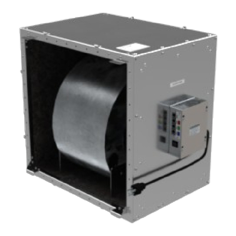
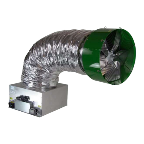
Fan Assembly Backdraft Damper*
Flex Duct
ELECTRICAL REQUIREMENTS
This fan requires a 120 volt, 3.3 amp uninterrupted electricity supply. We strongly recommend
providing a dedicated circuit for this fan.
This fan has two factory-installed, 10 ft. power cords. One originates at the control box, and the other at
the fan-mounted electrical box. Consider these lengths when choosing a location for this fan. Depending
on the location of existing outlets in the attic, the installation of an additional outlet may be required. Con-
sult an electrician if necessary.
All wiring and connections must be made according to this manual and acceptable wiring standards. All
local codes must be followed.
AirScape 2.5e Whole House Fan Installation Manual, 03152016
©AirScape, Inc., 2016. All Rights Reserved.
Page 3

INSTALLATION: FRAMING
AirScape 2.5e Whole House Fan Installation Manual, 03152016
©AirScape, Inc., 2016. All Rights Reserved.
Page 4
The 2.5e WHF hasbeen designed to t on top of a 14½"
x 22½" wall or ceiling opening. Since most modern
houses have been built with either 16" or 24" on-center
(O/C) spaced joists or studs, a simple "box" is construct-
ed in the wall as ceiling, as shown at right in Figure 1.
NOTE: There are two different installation methods de-
termined by how the 2.5e’s fan assembly will be moved
into the attic. Follow the instructions that apply to your
install.
If there is an existing attic access large enough for
the fan assembly to t through:
16” O/C Framing
1. Install two 14½" cross pieces creating a box with inside dimensions 14½" x 22½".
2. Cut out dry wall inside the framed box.
24” O/C Framing
1. Install two 22½" cross pieces creating a box with inside dimensions of 14½" x 22½".
2. Cut out dry wall inside the framed box.
If the fan assembly must t through the hole that is framed for it:
16” O/C Framing (shown in Figure 2 below)
1. Cut out the dry wall between the joists to create a 23” x 14½" rough opening.
2. Fit the fan assembly through the rough opening and into the attic.
3. Install two 14½" cross pieces creating a box with inside dimensions of 14½" x 22½". Make sure each
cross piece partially covers the drywall cut out. Approximately ¼” of each cross piece should be visible
from below.
24” O/C Framing (shown in Figure 3 below)
1. Cut a 23” x 14½" opening in the dry wall, use an existing joist as the 23” long side.
2. Fit the fan assembly through the rough opening and into the attic.
3. Install cross pieces creating a box with inside dimensions of 14½" x 22½". Make sure each cross piece
partially covers the drywall cut out. Approximately ¼” of each cross piece should be from below.
Figure 1
Figure 2 Figure 3

AirScape 2.5e Whole House Fan Installation Manual, 03152016
©AirScape, Inc., 2016. All Rights Reserved.
Page 5
Position the 2.5e damper enclosure on top of the joists
so that the damper doors are aligned with the framed
rough opening, as shown at right in Figure 4. Make sure
there is easy access to the electrical box located on the
side of the unit.
The actuator end of the damper box has two “key holes”
which are used to attach the damper box to the joists.
Mark the location of the “key holes” on the joists by plac-
ing the damper box over the rough opening. Remove
the damper box and fasten two of the provided wood
screws so that the screw head is slightly above the joist.
Position the damper box over the “key holes” and slide
to lock into position. Use the remaining screws to attach
the opposite side of the damper box.
If installing the damper vertically in a wall, frame a box with the same dimensions as above. However, use
longer wood screws than those provided (at least 1½˝ ) to mount the damper to the framing, and make
sure the damper door(s) open about their vertical axis. Also, consider bracing the underside of the damper
with additional framing.
Use a good quality latex caulk to seal all wood-to-wood and wood-to-metal joints to create an airtight
enclosure. This is important to ensure that all air drawn in by the fan will be from inside the house.
From below, attach the interior grille to the joists with the included wood screws.
INSTALLATION: BACKDRAFT DAMPER
Figure 4
INSTALLATION: BACKDRAFT DAMPER COLLAR
First, remove the two screws holding damper collar in place for shipping and ip collar.
Then, position the collar over the damper box opening and fasten the two together using 2 screws in the
holes at the top of the collar as shown below in Figure 5.
Next, as shown below in Figure 6, stretch the collar until the bottom 2 holes line up with the coorespond-
ing holes on the damper box body and secure the two peices together using 2 screws at these holes.
Finish fastening the damper box and collar together by using screws at each remaining hole.
Figure 5 Figure 6

AirScape 2.5e Whole House Fan Installation Manual, 03152016
©AirScape, Inc., 2016. All Rights Reserved.
Page 6
INSTALLATION: FAN & DUCT
Attach 4 lengths of the provided chain to the the attic’s rafters at four locations using wood screws (NOT
provided) screwed through a chain link. Alternatively, eye bolts (also NOT provided) can be anchored into
the rafters and additional S-hooks (also NOT provided) used to attach the chain thereto
Attach the 4 provided S-hooks to 4 of the D-rings attached to the fan housing. Hang the fan assembly
from the rafters using these S-hooks and the 4 lengths of chain just installed as shown below in Figure 7.
When hanging the fan assembly, adhere to the following guidlines:
• Do not hang the fan using fewer than 4 lengths of chains or eye bolts; all four attachment points are
necessary to support the fan’s weight and to eliminate any swaying motion.
• Ensure that the fan is as level as possible.
• Blocking this fan’s exhaust can cause it to fail prematurely. Keep the area in front of the fan as unob-
structed as possible: no object should be closer than 24” to the face of the fan.
Next, slide one end of the exible ductwork over the backdraft damper’s collar and fasten it thereto using
4 of the 8 provided self-tapping sheet metal screws.
Then, gently bend the ductwork to a 90 angle and slide the free end over the fan assembly’s collar and
fasten it thereto using the remaining 4 provided self-tapping sheet metal screws.
Figure 8 at the top of the next page describes the two ductwork conntections. Adhere to the following
guidelines when attaching the ductwork to the backdraft damper and fan assembly:
• Make sure to maintain the full diameter of the ductwork through the bend; this provides adequate
airow and helps minimize noise.
• Avoid sharp bends in the ductwork or contact with metal xtures, pipes, or conduits.
• The section of ductwork immediately before the fan should be as straight as possible.
• If necessary, the ductwork can be supported under the bend using extra chain wrapped with a protec-
tive material (e.g. carpet).
KEEP AIRSTREAM AS UNOBSTRUCTED
AS POSSIBLE
Figure 7

INSTALLATION: FAN & DUCT, cont.
AirScape 2.5e Whole House Fan Installation Manual, 03152016
©AirScape, Inc., 2016. All Rights Reserved.
Page 7
Once the fan assembly is balanced and secure, use pliers to close all of the S-hooks to ensure stability,
and tape down all unused D-rings to avoid excess rattling.
Then, use the provided duct tape to seal the joints between the ductwork and backdraft damper, and the
ductwork and fan assembly.
Figure 8
INSTALLATION: WIRING & CONTROLS
The standard control package included with this fan contains: the control box; 1 hardwired wall switch; 1
mounting bracket for the wired switch; 50 ft. of red CAT5 cable; and, 10 ft. of green CAT5 cable.
First, locate the control box mounted on the side of the damper. Look for a series of 5 RJ45 ports on one
side. These ports are labeled with the following label:
Next, connect the green CAT5 cable into the electrical box mounted on the fan assembly using either of its
RJ54 ports. Run the cable down to the control box and connect its free end to the green FAN port. This
cable is unshielded: Do not run it parallel to the fan assembly’s power cord.
Connect the red CAT5 cable to the red W/S port. Then, run the cable through the attic and down a wall
to the desired location for the hardwired wall switch. Note: This cable is low-voltage but unshielded.
Building Codes require unshielded low-voltage wiring to be run through shielded conduit.
Because a hardwired switch is necessary for providing technical support, the wall
switch included with this fan MUST be connected to the fan’s control box regard-
less of whether or not it will be installed in a wall. FAILURE TO CONNECT THE
HARDWIRED WALL SWITCH WILL VOID THIS FAN’S WARRANTY! If it is
not desired to be installed in a wall, the hardwired switch can be connected to the
control box and left in the attic with the CAT5 cable kept spooled.

AirScape 2.5e Whole House Fan Installation Manual, 03152016
©AirScape, Inc., 2016. All Rights Reserved.
Page 8
Figure 9
INSTALLATION: WIRING & CONTROLS, cont.
Using the provided mounting bracket as a template, trace an outline on the wall where the swich is de-
sired. Following this outline, cut a hole for the mounting bracket, place it inside, and secure it with the lock-
ing tabs by tightening the silver screws. Then, connect the free end of the red CAT5 cable to the port in
the back of the wall swich. Set the switch in place and secure its face plate to the mounting bracket using
the attached white screws.
Finally, plug each of the two power cords (one from the fan assembly and one from the control box) into
120-volt outlets with uninterupted power.
For reference, Figure 9 below describes this fan’s and its accessories’ general wiring scheme.

START-UP, OPERATION, & TECHNICAL SUPPORT
AirScape 2.5e Whole House Fan Installation Manual, 03152016
©AirScape, Inc., 2016. All Rights Reserved.
Page 9
Before starting this fan for the rst time, verify that:
1. All wiring and connections have been made according to this manual and acceptable wiring standards,
and that this manual and all local codes and standards have been followed in this fan’s installation;
2. No tools or construction debris have been left in, on, or around the fan;
3. Each of the two power cords (one from the fan assembly and one from the control box) have been
plugged into 120-volt outlets with uninterupted power; and,
4. The area in front of the fan is as unobstructed as possible, with no object closer than 24” to the face of
the fan.
When running this fan for the rst time, make sure to observe it turning on, running at each of
its speed settings, and turning off from both the attic (to see the fan itself) and the living space
(to see the backdraft damper).
Turn the unit on using the arrow up button on the wall switch control. The damper doors will open and
there will be a 10 second delay before the fan turns on. The fan will start in it’s lowest speed. Press the
arrow up button again to increase the fan’s speed to it’s next higher setting, allow for a slight delay when
changing speeds.
Use the arrow up button to increase the fan’s speed incrementally until it has reached it’s highest speed
setting. Then, use the arrow down button to decrease the fan’s speed incrementally until it has returned to
it’s lowest speed setting.
Press the timer button 1 time for 1 hour, up to 12 times for 12 hour operation. You can vary speeds while
the timer is programmed, but turning the unit off will cancel any remaining time.
When the power is turned OFF, the fans will shut down and the damper door(s) begin to close. The door(s)
will shut tightly within 60 seconds.
For additional operating tips, maintenance information, or troubleshooting tips, please see the War-
ranty card and Controls manual included with this fan. Please contact AirScape technical support at
tion, or maintenance of this fan.
MAINTENANCE & TROUBLESHOOTING
There is no routine maintenance required for this fan other than making sure the fan assembly and back-
draft damper are kept clean of any possible build up of debris, and that the area in front of the fan remains
as unobstructed as possible, with no object closer than 24” to the face of the fan.
Resettable circuit breakers are located on the control box and fan mounted electrical box to protect circuit
boards from power surges. In the case of a power surge, these breakers can be reset by simply pushing
the button back in.
If problems are encountered, please take a few moments to run through the troubleshooting procedures
described on the Warranty card. If these suggestions do not work, contact AirScape technical support at

AirScape 2.5e Whole House Fan Installation Manual, 03152016
©AirScape, Inc., 2016. All Rights Reserved.
Page 10
SPECIFICATIONS*
Speed Setting 1 2 3 4 5
TestedAirow(CFM): 800 1400 1600 1950 2550
TestedElectricityConsumption(watts): 40 50 70 110 205
TestedEfciency(watts/CFM): 20 28 22 17 12
TestedNoise(dBA): 36 – 54 dBA (min. speed to max. speed; tested at 45 and 1 meter from source)
Rough Opening Dimensions: 14.5” x 22.5”
Grille Outer Dimensions: 16” x 24”
Grille Build: Cube Core, Aluminum, White Powder Coat
Backdraft Damper Dimensions: 27” x 20.25” x 14.25” (L x W x H)
Duct Length: 7 ft.
Duct Diameter: 20”
Electrical: 110VAC, 60 Hz, 3.3 max amps
Insulation: R-10 standard, R-49 XR
Controls: Low Voltage; Hardwired Wall Switch, web interface, optional wireless remote
Installation: Installs easily on 24” or 16” O/C framing
Warranty: 3 years
*Actual performance will vary from installation to installation. Due to our continual product improvement
efforts, performance ratings and specications are subject to change without notice.
WIRELESSREMOTE(OPTIONAL)&WEBCONTROLS
A wireless remote is an available accessory for this fan. It is not included as part of this fan’s standard con-
trol package. See the yellow “Controls” manual for specic instructions for this accessory’s installation and
operartion. Briey, the steps for installing the remote are as follows:
• Plug the provided blue CAT5 cable into the remote receiver and the blue RMT port on the fan’s control
box. Renove the top cover of the remote receiver.
• Press and release the black button on the receiver’s circuit board to begin the merge sequence; the
transmission LED on the receiver will illuminate.
• Press and release any botton on the wireless transmitter while the transmission LED on the reciever is
illuminated; replace the top cover on the reciever.
This fan is network-enabled and can be connected to your home’s local area network by running CAT5
cable from the white WEB port on the control board to your router. If it is so connected, this whole house
fan can also be controlled by any computer, smartphone, or tablet with access to your home’s local area
network. For more details, visit our blog at blog.airscapefans.com and type “web control” into the search
eld.
This manual suits for next models
1
Table of contents
Other AirScape Fan manuals

AirScape
AirScape SAF10R User manual

AirScape
AirScape 3200 User manual

AirScape
AirScape 3400 VENTURA User manual

AirScape
AirScape 1.0 User manual

AirScape
AirScape 3.5E User manual

AirScape
AirScape X9 VENTURA User manual

AirScape
AirScape CVK-105 User manual

AirScape
AirScape ventura 2.7 User manual

AirScape
AirScape 2.5 Setup guide

AirScape
AirScape 3200 User manual
Popular Fan manuals by other brands

Breville
Breville AirActive 3D Connect Instruction book

Acorn
Acorn AC-309 instruction manual

Kemlan
Kemlan CELESTIAL 900 WITH FAN Installation & operating instructions

air&me
air&me FANTASY user manual

Vitek
Vitek VT-1940 Manual instruction

Helios
Helios KWL EC 500 W ET R Installation and operating instructions