AirScape AH2-CF-1600 User manual

AH2-CF-1600
AH2-CF-1900
Air Handler 2 – Cabinet Fan
Installation and Operation Manual
Images: AH2-CF-1900
© AirScape CF1600 / CF1900 Cabinet Fan-IOM, anuary 2023, All Rights Reserved. 1
Thank you for your purchase!

INDE
FRONT PAGE
SAFETY INFORMATION
SUPPLIES INCLUDED
REQUIRED TOOLS AND SUPPLIES NOT INCLUDED
ELECTRICAL REQUIREMENTS
SYSTEM INSTALL GUIDE
INSTALLATION OF THE DUCT
INSTALLATION OF WIRING AND CONTROL
PURCHASE OPTIONS (not included)
START-UP AND OPERATION
DTC CONTROLLER
FAN BO BOARD
MAINTENANCE
G LO S SARY
TROUBLE SHOOTING
SPECIFICATIONS
ELECTRICAL SCHEMATICS
© AirScape CF1600 / CF1900 Cabinet Fan-IOM, anuary 2023, All Rights Reserved. 2

SAFETY INFORMATION
Some of the principles of this product’s safe installation and
operation are not immediately obvious. Read the following
safety information before continuing further:
• This fan is meant for general ventilation. It has NOT been designed to ventilate particle laden and/or
explosive mixtures of air.
• This fan is not for use in kitchens.
• Never force open the damper door(s), this could severely damage the actuator (If Purchased).
Always depress the actuator’s yellow clutch release before manually opening or closing the damper door(s).
• Before installing or servicing this fan, switch power off at the home’s electrical panel to reduce
the risk of damaging circuit boards, fire, electrical shock, or injury.
SUPPLIES INCLUDED
Prior to beginning installation, please verify all of the following items were received:
• Cabinet Fan Assembly, check, note serial. (see Specifications for identification of the main parts)
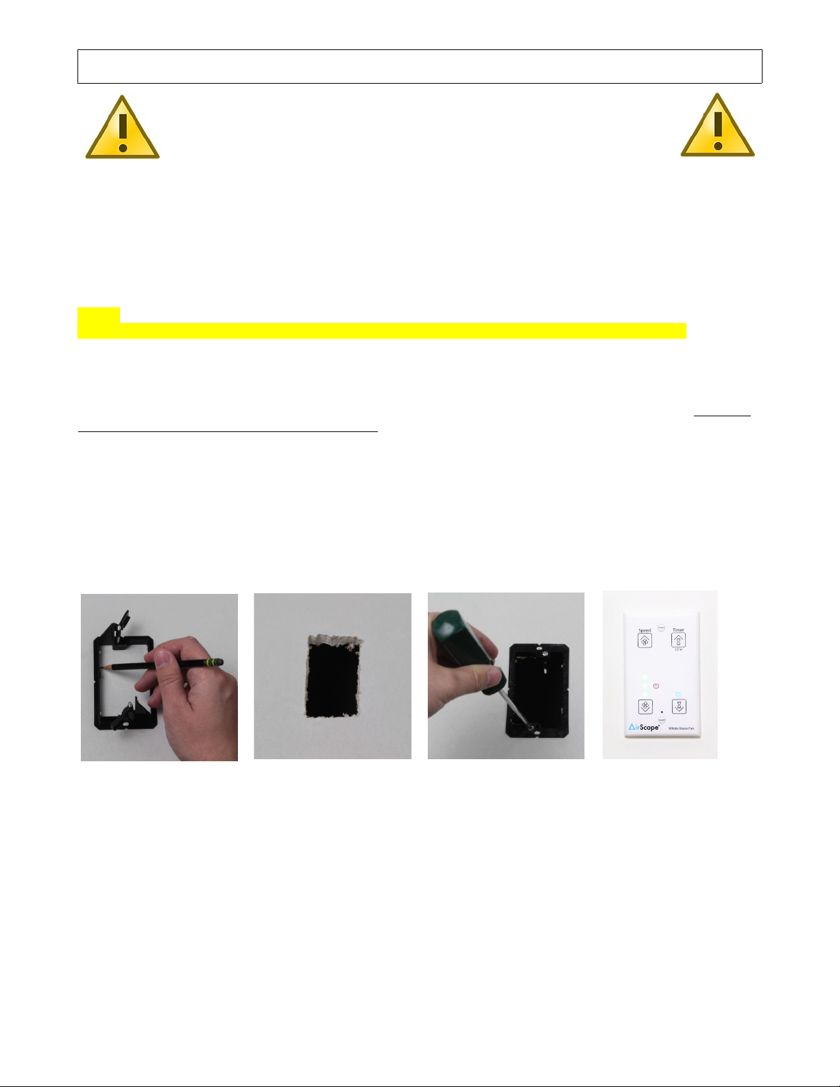
• Digital Touch Controller package—including one Digital Touch controller, one wall mounting bracket,
mounting screws and 30 feet of red shielded CAT5 cable.
Once all received parts are verified, perform an operational test BEFORE installing it in the attic. See “Installing
the Controller” and “Start-up and Operation” for connections to be made. This is a good time to write down the
serial number(s) on this IOM, which will save you a trip to the attic if you require Tech Support
REQUIRED TOOL & SUPPLIES NOT INCLUDED
In addition to the included items listed above, the following tools and supplies are required to install the Cabinet
Fan:
• Safety Glasses, Gloves
• Receptacle tester
• At least 8 wood screws (1½" min. length) and washers sized to fit. (to hang the Fan)
• Cordless screwdriver with Phillips head and miscellaneous drill bits
• High quality caulk and Butyl Tape to seal all duct to fan, duct to duct connections.
• Fishing tape or similar tool (to pull control cable through the wall)
ELECTRICAL REQUIREMENTS
The AH2-CF model Cabinet Fan requires a 120 volt, Single Phase, 60 Hz, 15A uninterrupted power supply.
These specifications must be taken into account when allocating power from existing circuits. We strongly
recommend providing a dedicated circuit. All wiring and connections must be made according to this manual and
acceptable wiring standards. All local codes must be followed. Consult an electrician if necessary.
This Circuit MUST be Ground Tested. This can be done easily using a receptacle tester available at most
hardware stores. This fan has a factory-installed, 20 ft. power cord. Consider this length when choosing a
location for this fan. Depending on the location of existing outlets in the attic, the installation of an additional
outlet may be required. NOTE: if a GFCI is used it MUST be a Motor Rated GFC
© AirScape CF1600 / CF1900 Cabinet Fan-IOM, anuary 2023, All Rights Reserved. 3
INDEX

SYSTEM INSTALL GUIDE
The AirScape Cabinet Fan is going to be, placed in an mechanical room or a crawl space or the attic, residing in
an area not easily accessed. It is wise to “plan” and document your Fan Installation.
If you have purchased additional modules with your Cabinet Fan, they will arrive attached to eachother on a
palette. We advise creating a system assembly drawing documenting your actual installation after you planned
out the installation space chosen on the same document.
Pay particular attention to fitting the entire Air Handler it’s ducting, wiring and mounting in an as accessable way
as possible. Determine where there is an existing power socket within reach of the fan’s 20 foot power cord is
there enough clearance for the fan to exhaust properly. It would be great if you did not need an electrician to
install Your Fan. (All dimension can be taken from the units as shipped to you, or see Specifications)
Determine where there is space to access the fan or filter modules leaving enough room to service and change
filters (if you purchased that). All these decisions in your installation will influence the installation cost. Make sure
the Air Handler 2 and duct work FIT in the space you selected. You may want to connect to an existing duct
system. Think routing and parts and sizes. You may want to pay attention to the aesthetics and reach of the 30
feet red control cable of the Digital Touch Controller.
All Air Handler 2 modules come with corner mounting screws which will facilitate secureing the entire unit in
multiple places. We strongly urge you to use butyl tape on all unit to duct connections to properly seal these
connections.
NOTE: DO NOT INSTALL THE DTC CONTROLLER NEXT TO HOME AUTOMATION DEVICES (nest etc.)!
IF YOU PURCHASED A REMOTE MAKE SURE YOU MOUNT THE RECEIVER!
INSTALLATION OF THE DUCTS
The Cabinet Fan as shown here comes without duct
adapters on the inllet and exhaust of the fan.
These can be purchased, please call us 1.866.448.4187
for your custom size.
We strongly advice using butyll tape to seal all unit-adapter
or unit-duct connections.
© AirScape CF1600 / CF1900 Cabinet Fan-IOM, anuary 2023, All Rights Reserved. 4

INSTALLATION OF WIRING AND CONTROL
The Digital Touch Controller provided with this fan is
necessary for operating it, and must be connected to it
regardless of whether the controller will be installed in a wall.
This fan will not function if not connected to a digital touch controller!
If it is not desired to be installed in a wall, the controller can be connected to the fan and kept in the installation
space with the shielded CAT5 cable kept spooled. Note: you will need a remote to operate it.
The WebNode option (when available) may also be used to operate the system.
The standard control package included with this fan contains 1 wall-mounted Digital Touch Controller plus
screws; 1 mounting bracket for the controller; and 30 ft. of Red Shielded CAT5 cable.
NOTE:
DO NOT INSTALL THE DTC CONTROLLER NEXT TO HOME AUTOMATION DEVICES (nest, etc.)!
First, locate the desired location for the Digital Touch controller.
Install the mounting bracket according to figures A–C below.
Return to the attic and connect the red CAT5 cable to the R 45 port on the control box labeled W/S (red).
Run this cable from the control box to the location of the controller. NOTE: this is a low-voltage cable, DO NOT
RUN IT PARALLEL TO HIGH-VOLTAGE WIRING; building codes generally require low-voltage cable to be run
through shielded conduit.
NOTE: Carefully unwind and run the CAT5 Cable down the wall,
AVOID kinks as this can damage the Cable conductors!
Connect the CAT5 cable to the R 45 port on the back of the Digital Touch controller. Mount the controller to the
mounting bracket with the provided white screws, DO NOT over-tighten (figure D).
Fig. A: Fig. B: Fig. C: Fig. D:
© AirScape CF1600 / CF1900 Cabinet Fan-IOM, anuary 2023, All Rights Reserved. 5
Use the mounting
bracket as a
template to mark the
hole location
Cut out the hole Place the mounting
bracket and secure
its locking tabs by
tightening the silver
screws
Connect the CAT5
cable Mount the
DTC to the bracket
with the provided
white screws
INDEX

All wiring connections to the fan assembly are made at the fan-mounted electrical box.
These are a 20 ft, black, factory-installed power cord, a 10 foot actuator power harness and three R 45
(“Ethernet”) ports for connecting the fan controls and accessories (see below) Color Match Cable and ack
Identification
Note: The “WEB” port is not available yet but can be upgraded at a later time.
PURCHASE OPTIONS
A wireless remote is an available accessory option for this fan. The wireless remote is NOT included as
part of this fan’s standard control package. The yellow manual included with these accessories provides specific
instructions for the installation and operation of the remote. If purchased, the wireless remote receiver is
connected to the fan-mounted electrical box at the blue RMT R 45 port. (see above)
A Web Node is another option not included in the standard WHF package. This will allow you to control your fan
using your mobile phone or tablet or home automation device through a web page or an app. The Web Node
comes with a white cable and connects the Web Node to the WEB port. (see above) The yellow manual included
with these accessories provides specific instructions for the installation and operation of the Web Node. Note:
The “WEB” port is not available yet but can be upgraded at a later time.
Furthermore several modules are available, specifically designed for the Air Handler 2 Series Cabinet Fan
(call for details 1.866.448.4187 ):
- a V-Bank Filter Box Module (AH2-FB)
- an Air Inlet Selector (AH2-AIS)
- a Hot Water Coil Box (AH2-CB)
- Air Handler Duct Adapters for Intake and Exhaust
© AirScape CF1600 / CF1900 Cabinet Fan-IOM, anuary 2023, All Rights Reserved. 6
Blue 5 foot CAT5
shielded Ethernet Cable
connect to RMT and
Receiver (Optional NOT
included)
20 foot Power Cable
connect to Wall Outlet
Red 30 Feet CAT5
Shielded Ethernet Cable
connect to W/S and DTC
INDEX

START-UP AND OPERATION
Before starting this Fan for the first time, verify that:
•All wiring and connections have been made according to this manual and acceptable wiring standards,
and that this manual and all local codes and standards have been followed in this fan’s installation.
•No tools or construction debris have been left in, on, or around the fan.
•The fan’s power cord has been plugged into a ground tested, 120-volt outlet with uninterrupted power.
When running this fan for the first time, make sure to observe it turning on, running at all of its speed settings,
and turning off. Observe it with the access panel open (to observe the fan itself) and observe its damper door(s)
(if purchased), also verify Timer works at 1 Hour Setting.
As shown, there are four buttons on your fan’s control interface:
The AirScape WHF has ten speed settings. Turn on the Fan by touching FAN UP or TIMER UP. Its door(s) will
open and there will be a 10 second delay before the fan begins to operate (PAL’s / Lift-Lock Only). The fan will
start at minimum speed. Green LED’s will illuminate to indicate the speed setting.
Note: there is no delay on a unit with gravity doors.
If the Fan was turned on by TIMER UP, the timer will be set to one hour and blue LED’s will illuminate to indicate
the timer setting. Press or hold FAN UP to increase the fan’s speed to maximum. Press or hold TIMER UP to
increase the length of time the Fan stays on in one hour increments until the desired time, or the maximum time
of 12 hours, is achieved.
If the fan is already operating at minimum speed, touch FAN DOWN/OFF to turn off the fan; any time remaining
on the timer will be canceled. If the fan is at maximum speed, press or hold FAN DOWN/OFF to decrease the
speed to minimum and once again to turn the fan off.
Press or hold TIMER DOWN/CANCEL to reduce the time on the timer by one hour increments until the desired
time is achieved or the timer is canceled. When the timer expires, the fan will turn off automatically. If the timer is
canceled, the fan will remain on at its current speed.
Whenever the fan is turned off, its damper door(s) will close tightly within about 60 seconds.
* Note: If untouched after a moment the selection LED’s will dim.
© AirScape CF1600 / CF1900 Cabinet Fan-IOM, anuary 2023, All Rights Reserved. 7
Fan Speed UP
Power Symbol
may or may not
be there
Fan Speed DOWN
Timer UP
Power Reset
(Stand Alone DTC)
Light Sensor
(web capable DTC)
Timer Down
INDEX
INDEX

DIGITAL TOUCH CONTROLLER – DTC
Although your DTC should arrive with all the proper settings for the system you purchased we
include this information.
The function of the Digital Touch Controller is dependent on the configuration of the DIP switches and
pin jumper located on the back of the PCB. The jumper pins are located to the left of the R 45 port, and
the DIP switches are immediately below it.
The jumper is configured by placing it to connect two of the three pins, as shown (pin 1-2). *
The DIP switches are configured by switching them to the ON or OFF
position, depending on the switch number. A DIP switch in the ON position
is set away from its number, and towards the side labeled ON, as shown.
MODEL UMPER SETTING DIP SWITCH SETTING
AH2 – Air Handler 2 with AIS (Air Inlet Selector)
Any unit with actuated doors requires a delayed fan
start. (time delay)
Pin 1-2*
(24VDC PWM)
Pin 2-3*
(0-10VDC)
(time delay**)
AH2-CF-1600 / 1900
AirScape Fan without an AIS (Air Inlet Selector)
Units without doors can be started immediately
(no time delay / direct start)
Pin 1-2*
(24VDC PWM)
Pin 2-3*
(0-10VDC)
(direct start)
* Pin 1-2 = 24VDC PWM Motor speed control/ Pin 2-3 = 0 – 10 VDC Motor speed control.
Most fans have a PWM controlled motor, but newer CF’s can be 0-10VDC controlled.
** Time delay allows the door(s) to open before the fan starts
Rear View of the
Digital Touch Controller
R 45 ack
Speed
Control
Format
umper
Dip Switch
© AirScape CF1600 / CF1900 Cabinet Fan-IOM, anuary 2023, All Rights Reserved. 8
INDEX

FAN BO BOARD
There is quite a bit of white text on the board, labeling these connections.
The Actuator Relay (door) has 24VDC on the COM terminals ( P1=shunted). This provides power to the
actuator(s) of your AH2-AIS (Air Inlet Selector) if you purchased it.
Fan speed control signals can be put out in both formats and are chosen on the DTC ( P1, see DTC above). On
this fan board (SCAB) the motor control wiring is connected to two spade connectors. The negative = “Ground”
spade and the positive = “Fan Cntl” Spade.
The Red LED D4 comes on with power to the board and the Red LED D2 comes on when the controller calls for
a fan start and activates the doors (fan will start after a 10 second delay if selected)
Interlock:
This allows you to disable operation of the unit while other appliances are active, such as heating or cooling
systems. While triggered, this interlock disables the fan and sets the damper doors to the Off position, but does
not reset the current fan speed as displayed on the Digital Touch controller. Removal of the interlock allows the
unit to resume the previously set fan speed. The Timer function will continue to operate normally while the
interlock is active.
It is important that no voltage be sent to the board from external sources when choosing how to wire this
interlock. It is designed to operate only as a closed loop circuit. This interlock is controlled with the INT and GND
contacts on terminal block P4, on the SCAB. This board is found inside the junction box mounted on the fan unit.
This interlock is triggered by closing the circuit between two contacts on the board. The exact method of closing
this circuit will depend on the particular installation and equipment the controller is interfacing with. One possible
way of doing so is with a double-pole wall switch, in which it it wired so that one pole is used to control power to
the appliance and the other pole closes the interlock contacts. Another way would be to use a relay or current
switch that is activated when the appliance is turned on. An Fire Alarm may call for the ”InterLock” as well
© AirScape CF1600 / CF1900 Cabinet Fan-IOM, anuary 2023, All Rights Reserved. 9
W/S FAN RMT
POWER
HEADER
ACTUATOR
HEADER SHUNT
INTERLOCK
HEADER
+ Fan
Control
- Fan
Control
Ground
INDEX

MAINTENANCE
There is no routine maintenance required for the Fan other than making sure the Fan and its damper door(s)
remain clear of dust or debris, and that the duct connection remian sealed.
We however advise that you check the operation of the doors and fan at the start of each season.
A re-settable circuit breaker is located on the Fan-mounted electrical box to protect circuit boards from power
surges. In the case of a power surge, this breaker can be reset by simply pushing the button back in.
GLOSSARY
AD: Air-Door, a gravity door made to seal well and open with little effort includes framing (latest versions),
requires a grille
CEC: California Energy Commision.
CFM: Cubic Feet per Minute.
dBA: Decibels A is a noise level measured in decibels (dB) 60dBA is considered conversation level noise.
DTC: Digital Touch Controller
DVS: Direct Venting System.
GFCI: Ground Fault Circuit Interrupter, for systems using a motor use a Motor Rated GFCI.
Hz: Hertz equals the number of cycles per second (alternating currents)
LL: Lift-Lock TM Actuated insulated door installed from the living space (no grille)
O/C: On Center, indication of framing distance between beams measured in the center of the beam.
PAL: Powered Air-Lock TM Actuated Door(s) usually insulated, requires a grille
PSU: Power Supply Unit.
PWM: Pulse Width Modulation is used for controlling the amplitude of digital signals in order to control
motor speed or other devices.
SCAB: Simple Controller Attic Board or Fan Box Board (located on the fan)
VA: Volt-ampere (VA) is a measurement of power in a direct current (DC) electrical circuit 1 VA = 1W
VAC: Volts Alternating Current.
VDC: Volts Direct Current.
WHF: Whole House Fan a ventilation system intended for cooling the entire house.
TROUBLE SHOOTING
Before servicing your cabinet fan, turn off power to it at your
home’s electrical panel to reduce the ris of electrical shoc ,
injury, fire, and/or circuit board damage.
Your AirScape Fan has been factory tested. If you encounter problems with the unit, please take a few minutes
to run through the following troubleshooting procedures before calling for technical support.
NOTE:
A “ in ed” CAT5E Cable may cause all of the listed symptoms. Use a second short cable and plug the
wall switch (controller) directly into the W/S port on the fan to rule out a cable issue before
proceeding.
A re-settable circuit breaker is located on the Fan-mounted electrical box to protect circuit boards from power
surges In the case of a power surge, this breaker can be reset by simply pushing the button back in
© AirScape CF1600 / CF1900 Cabinet Fan-IOM, anuary 2023, All Rights Reserved. 10
INDEX

Symptom: Unit does not start
Possible causes: No power to unit or kinked Ethernet Cable
Suggestion 1: Open Fan Box, is the power LED on the SCAB* on?
Reset main Power (unplug, wait 10 sec., plug in).
Suggestion 2: Check the re-settable circuit breaker on fan’s electrical box.
Suggestion 3: Take DTC** into the attic and connect it to the W/S port using another CAT5 Cable.
Suggestion 4: Check power (115VAC) at the electrical outlet, inside the fan’s electrical box wiring at
both the power supply (115VAC) and the SCAB* (24VDC inside the fan’s electrical box).
** D TC = Digital Touch Controller
* SCAB = Simple Controller Attic Board / Fan Box Mounted Board
Symptom: Door(s) does not open, but Fan starts ((AIS /PAL / LiftLoc ) actuated units only).
Possible causes: No power to damper actuator, or damper shaft loose.
Suggestion 1: Operate door(s) manually using the Actuator Clutch. Verify that the Actuator rotates with
the door shaft and that the shaft rotates with the door.
Suggestion 2: Check for 24VDC at the actuator(s) harness and at the SCAB*
(fan’s electrical box, see schematic)
Symptom: Door(s) open but Fan does not start ((AIS /PAL / LiftLoc ) actuated units only).
Possible causes: Wiring issue between SCAB* and Fan
Suggestion 1: Open Fan’s electrical box and check for power (115VAC) at the fan’s power wires.
Suggestion 2: Check for pwm (control 0-24VDC, 80Hz PWM) signal at fan’s control wire connections
on the SCAB* this can be done using a volt meter set to dc but gives approximate values.
Symptom: Wireless remote does not Operate.
Possible causes: Battery, RF interference.
Suggestion 1: Check transmitter’s battery for power. Replace if necessary, NOTE: POLARITY.
Suggestion 2: Check to see if LED on the remote receiver is lit. Open the cover and see if the internal
LED’s respond by pressing a button on the remote.
Suggestion 3: Temporarily replace the CAT5 Ethernet cable with another cable.
Suggestion 4: Check for red LED response on DTC (stand alone only) when pressing the remote buttons.
DTC trouble shooting
When the Digital Touch Controller (DTC) is connected to the fan, and the fan to power, a red LED will illuminate
on the face plate If the Power Indicator is not illuminated; double-check the connections between the fan and
the controller, between the fan and the power outlet and power at the outlet
If problems are encountered, please ta e a few moments to run through the troubleshooting
procedures described on the blue Warranty Card. If these suggestions do not wor , contact AirScape
technical support at 1.866.448.4187 or by email at exper[email protected] for further assistance.
NOTE: You will be asked for the serial numbers of the Fan and PAL.
NOTES
© AirScape CF1600 / CF1900 Cabinet Fan-IOM, anuary 2023, All Rights Reserved. 11
INDEX
INDEX

SPECIFICATIONS
Dimensions Fan: 22” H x 22” W x 16” L
Fan Duct Adapter: No (call us)
Weight Fan: 43 lbs
Motor: 1/3 HP - 1/2 HP
Electrical: 120 VAC, 60 Hz, 15 A
Installation: Mounting Screws
Controls: Low Voltage,
Digital Touch Controller
optional wireless remote
Speed Settings: 10
Warranty: 3 years parts, 1 years
controls
* Actual performance will vary from installation to installation
Due to continual product improvement, performance
ratings and specifications are subject to change without
notice.
© AirScape CF1600 / CF1900 Cabinet Fan-IOM, anuary 2023, All Rights Reserved. 12

ELECTRICAL SCHEMATIC
* Note: IF YOU PURCHASED THE AIS, showing one actuato
© AirScape CF1600 / CF1900 Cabinet Fan-IOM, anuary 2023, All Rights Reserved. 14
Optional Remote
Optional Remote
Recei er
Fan Motor
EL-714
Power Supply
120V
AC IN,
24VDC OUT
SCAB/FAN BOX BOARD
24V Actuator*
(co er off)
24VDC
Motor Control Harness (24V PWM) EL-603 Optional Blue
CAT5E Cable (5ft)
EL-605 Red CAT5E (Ethernet) Cable (30ft)
Jumper
Shunt
EL-728 Actuator Harness
Clutch
Directional
Switch
FAN BOX
EL-734
EL-733
Circuit
Breaker
EL-9013
20 foot Power Cord
120VAC, 1 Phase, 7.8A Max.
Mechanical
Limiters
INDEX
Digital Touch Controller
This manual suits for next models
1
Table of contents
Other AirScape Fan manuals

AirScape
AirScape 2.5E Operating instructions

AirScape
AirScape 3200 User manual

AirScape
AirScape SAF10R User manual

AirScape
AirScape 2.5 Setup guide

AirScape
AirScape 3200 User manual

AirScape
AirScape ventura 2.7 User manual

AirScape
AirScape CVK-105 User manual

AirScape
AirScape 3400 VENTURA User manual

AirScape
AirScape 1.0 User manual

AirScape
AirScape 3.5E User manual