AirTech Air+ PIV Installation and operation manual

PLEASE READ INSTRUCTIONS IN CONJUNCTION WITH THE ILLUSTRATIONS.
PLEASE SAVE THESE INSTRUCTIONS
Positive Input
Ventilation Unit
A
ir+ PI
V
AIR+PIV/L
Installation & Commissioning
I
nstructions
220-240V~50Hz

2

3
Installation and Wiring Instructions for the
Air+ PIV Unit.
IMPORTANT: READ THESE INSTRUCTIONS BEFORE
COMMENCING THE INSTALLATION
SAFETY AND GUIDANCE NOTES
1. DO NOT install this product in areas where the following may
be present or occur:
1.1. Excessive oil or a grease laden atmosphere.
1.2. Corrosive or flammable gases, liquids or vapours.
1.3. Ambient temperatures higher than 40°C or less than -5°C.
1.4. Possible obstructions which would hinder access or removal
of the Fan.
1.5. Relative humidity above 90%
1.6. Sudden ductwork bends or transformations close to the Unit.
2. All wiring to be in accordance with the current I.E.E.
Regulations, or the appropriate standards of your country and
MUST be installed by a suitably qualified person.
3. The fan must be provided with a 3A fused, isolator switch
capable of disconnecting all poles, having a contact
separation of at least 3mm.
4. Ensure that the mains supply (voltage, frequency, and phase)
complies with the fan’s rating label.
5. The fan should not be used where it is liable to be subjected
to direct water spray.
6. This appliance can be used by children aged from 8 years and
above and persons with reduced physical, sensory or mental
capabilities or lack of experience and knowledge if they have
been given supervision or instruction concerning use of the
appliance in a safe way and understand the hazards involved.
Children shall not play with the appliance. Cleaning and user
maintenance shall not be made by children without supervision.
7. Precautions must be taken to avoid the back-flow of gases into
the room from the open flue of gas or other fuel-burning
appliances.
8. Children of less than 3 years should be kept away unless
continuously supervised.
9. Children aged from 3 to 8 years shall only switch on/off the
appliance provided the unit is installed as intended for
normal operation and they have been given supervision or
instruction concerning safe use of the appliance and
understand the hazards involved.
10. Children aged 3 to 8 shall not plug in, regulate and clean the
appliance or perform user maintenance
Caution - some parts of this product can become very hot and cause
burns. Particular attention has to be given where children and
vulnerable people are present.

4
A. INTRODUCTORY NOTES
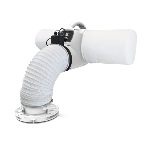
The Airtech Air+ PIV is a positive input ventilation unit, designed to be installed in
the loft of a dwelling to continually supply filtered fresh air into the building.
The system consists of a fan unit, a heater unit and a diffuser with a short length of
flexible ducting.
The Airtech Air+ PIV has two fully adjustable speed settings; ‘Trickle’ and ‘Energy
Recovery’. These speeds are set during installation; there are 5 pre-set speeds or an
option allowing the speeds to be chosen manually from 10L/s to 60L/s.
The Airtech Air+ PIV uses a sensor to monitor the temperature in the loft,
automatically adjusting the air volume when necessary.
‘Trickle’ speed is automatically selected when the ambient loft temperature is less
than 18°C.
‘Energy Recovery’ is automatically selected when the ambient loft temperature is
between 18 and 27°C.
If the ambient loft temperature exceeds 27°C, the Airtech Air+ PIV will automatically
switch to standby (no airflow).
For the heater unit, the element is activated by default when the loft air temperature
is below 10°C; the system will then work to maintain an input air temperature of 10°C.
This temperature threshold can be adjusted between 5°C and 20°C during commissioning.
The heater unit can be installed either to the fan unit or directly to the diffuser
spigot.
The unit also incorporates a data logging function. This function will display total
runtime of system, time spent in trickle speed, time spent in Energy Recovery speed,
approximate energy consumption of the fan and approximate energy consumption of the
heater unit. This data is non-resettable.

5
INSTALLATION
TYPICAL INSTALLATION
Air+ PIV UNIT:
Prior to installation ensure that the loft is adequately ventilated. The following
tips can be used as a basis for this. However this is not an exhaustive list.
Ensure that any ridge vents, tile vents and continuous air gaps are not blocked. These
may not be present in older properties; however there should be enough ‘leakage’ to
accommodate the requirements of the Air+ PIV unit.
One method of checking this is by entering the loft, closing the loft hatch, switching
off the lights and looking for any daylight penetration. If daylight is visible it is
reasonable to assume that there is adequate ventilation within the loft.
There may well be occasions where a loft is so well sealed that additional ventilation
may need to be provided by the owner/occupier. This will not only assist the operation
of the Air+ PIV, but may also help to prevent future expensive structural damage
caused by inadequate air movement. It should be noted that there can never be too much
ventilation in a loft.
Ensure that all water tanks are covered and sealed.
Check that all water pipes are lagged.
Ensure that any extract fans are discharging to the outside and not into the loft.
Check that the loft hatch is tightly sealed.
Ensure that all holes in the ceilings are sealed, i.e. ceiling light fittings etc.
A visual inspection of any flues or chimneys for leakage in the loft should be carried
out by the installer.
If any leakage points are found, or if there is any doubt at all, the installer should
advise the house owner/provider as soon as possible and seek instruction from them
before proceeding with the installation.
Flexible ducting is supplied as standard. Ensure that this is pulled out and does not
allow any moisture to collect; it should be a smooth single curve to the grille. If
the application requires a fixed 90 degree bend, straight ducting may be used. See
Spares and Accessories on page 13.
Fig.1.

6
Hanging method:
The Air+ PIV can be hung from a roof beam (Fig. 2). Fix the screw eye to a convenient
roof beam. Use the cord provided to loop through the eye and around the handle on the
unit, there are various notches for the cord to run through, tie the two ends together
using a suitable knot such as an over hand or fisherman’s knot.
Ensure that the route for the flexible ducting has gentle bends and that the duct
cannot be crushed.
Fit the filters to the unit. Please make sure that the filter is fitted correctly.
This will ensure that all the fresh air entering the dwelling has passed through the
filter first.
Ensure that the screw eye is attached to the beam strongly enough and that the beam is
in sufficient condition to withstand the load. The unit weight is approximately 4 kg.
Floor mounting:(USING ACCESSORY MOUNTING BASE – 477749 – Not supplied)
Find a suitable location to fix the unit near to where the diffuser is to be located.
Ensure that the route for the flexible ducting has gentle bends and that the duct
cannot be crushed.
Affix the mounting base to a wooden board or two lengths of timber which can then be
screwed to the joists.
Place the unit in the mounting base cradle; two retaining pins hold the unit in place.
Fit the filters to the unit. Please make sure that the filter is fitted correctly.
This will ensure that all the fresh air entering the dwelling has passed through the
filter first.
Filters
Fig. 4.
Fig.2.
Fig. 3.

7
DIFFUSER GRILLE:
The heater unit must not be located directly below a socket.
The diffuser must be carefully sited to ensure the maximum effectiveness of the
system. It should be fitted in the ceiling of a common area, ideally above the landing
so that the incoming air can reach all the rooms.
Cut the flexible ducting to a suitable length, where possible stretch the ducting to
its maximum extent and ensure that there is one continuous smooth bend to the
diffuser. The ducting must remain a minimum of 1m in length.
Remove the loft insulation from the location of the diffuser and cut a 240-260mm dia
hole in the ceiling.
Ensure the four locking tabs are folded in and then push the spigot in to the hole.
Holding the diffuser in place; screw the four screws until the locking tabs are
holding the diffuser tight against the ceiling. Fig. 5 It is important not to over
tighten these screws as this may warp the diffuser.
Fit the free end of the flexible ducting to the diffuser spigot using the worm drive
clip supplied.
The diffuser should not be situated within 1m of a smoke detector, however if this is
not possible the AIR+ PIV has provisions to blank off the airflow for up to two
quadrants of the diffuser. Two blanking plates are provided; these should be pushed on
to the support struts inside the diffuser as required. This should be done before the
diffuser is installed in the ceiling as when the screws are tightened down the plates
can no longer be removed. Fig.6
Blanking off one side reduces the flow by about 6%, but blanking off two sides reduces
the flow by about 20% and so if two sides are blanked off then you should consider
increasing the fan speed to maintain the appropriate airflow.
Fig. 5. Fig. 6.

8
Heater Unit
The heater unit can be mounted either to the unit or to the diffuser spigot, see Fig
7, where fitted to the unit there are locating pins that fix the heater to the unit
using a bayonet fitting and the locking screw. When fitted at the diffuser end, make
sure the direction of the heater is facing the correct way, arrow label on heater must
point towards diffuser. The power and sensor cables must be plugged in to the front of
the fan unit; see Fig 8.
C. WIRING
WARNING: THE POSITIVE VENTILATIION UNIT AND ANCILLARY
CONTROL EQUIPMENT MUST BE ISOLATED FROM THE POWER
SUPPLY DURING THE INSTALLATION / OR MAINTENANCE.
A MEANS FOR DISCONNECTION MUST BE INCORPORATED IN THE FIXED WIRING IN ACCORDANCE WITH
THE WIRING REGULATIONS.
Mains supply voltages (220-240V ac) are present in this equipment which may cause
death or serious injury by electric shock. Only a qualified electrician or installer
should connect the power supply to this unit.
The Air+ PIV is designed for operation from a single-phase alternating current source
(220-240V AC).
A 2m integral mains flying lead is connected to the unit for connection to a 3A
switched fused spur. It should be capable of disconnecting all poles, having a
contact separation of at least 3mm.
Fig. 7.
Fig. 8.
Unit Mounted
Apply worm drive clips provided
in positions shown
Apply worm drive clips provided
in positions shown
Apply suitable duct tape to seal
between heater and diffuser.
Diffuser Mounted

9
WARNING: If the supply cord is damaged, it must be replaced
by the manufacturer, its service agent or a similarly
qualified person in order to avoid a hazard
Ensure the local AC power supply is isolated.
The product has a pre-wired flying lead. Connect the brown core to Live and the
blue core to Neutral.
Use cable clamps and clips to secure the cable, as appropriate.
D. START UP SEQUENCE
When the unit is switched on it will first run through a period of system checks.
During this time the display will show various system parameters before the fan motor
starts. After 10 seconds the product will be ready for commissioning.
E. COMMISSIONING
Accessing the Commissioning Menu
If the fan is powered and the display is not lit then press any button to access the
menu. After 20 seconds without menu activity the display will switch off; any new
settings will then be applied.
There are three buttons on the front of the unit:
+
-
SET
IMPORTANT:
In order to have the product
switch off in the event of a fire
it must be wired using a smoke
alarm with a relay system.
Use Fig.9 as a reference and
refer to the instructions
provided by the manufacturer of
the smoke alarm and relay in
order to wire the unit correctly.
FOR REFERENCE ONLY
Air+ PIV
Unit
Fig.9

10
The + button is used to increase the value of a setting, the – button is used to
reduce the value of a setting and the SET button moves to the next menu item.
Lock feature
If the lock feature is enabled; when a button is pressed the display will show, – – –.
At this point enter the three digit code by first pressing + or – until the first
digit is correct then press MODE to move to the next digit. Repeat until the code is
entered and press MODE to enter the commissioning menu. If the code is entered
incorrectly, wait until the screen switches off then press any button to begin again.
Air filter
The Airtech Air+ is provided with G4 filters which are suitable for removing airborne
contaminants such as pollen and dust.
Where improved filtration is required optional F7 filters can be used. These filters
are effective at removing finer particles such as particulate emissions from diesel
engines. In urban areas close to main roads F7 filters are advisable in order to
ensure the supply air is clear of these particles which are potentially harmful to
health.
Where F7 filters are fitted, please ensure the flow rate of the fan is as expected. F7
filters cause extra system resistance so it may be necessary to increase the fan speed
to compensate

11
Commissioning Menu Structure
For most installs the standard features allow for ample adjustability, however in some
install situations the advanced features will improve the unit’s performance or
acceptability.
By reducing the trickle speed threshold the fan will run at Energy Recovery speed more
often, this would be helpful in a property with persistent damp problems.
Increasing the temperature limit will mean the fan will continue to run at higher
temperatures, note radon mode being on means the unit will ignore this setting.
The menu lock feature will prevent the unit from being adjusted after commissioning as
a pass code is required to access the menu. This can be set in the menu to any 3 digit
hexadecimal combination.

12
Speed Settings
The Air+ PIV has two speed settings, ‘Trickle’ and ‘Energy Recovery’. ‘Trickle’ speed
is automatically selected when the ambient loft temperature is below 18°C. ‘Energy
Recovery’ is automatically selected when the ambient loft temperature is between 18°C
and 27°C.
If the ambient loft temperature exceeds 27°C, the Air+ PIV automatically switches to
standby (no airflow) unless in Radon mode. If in Radon mode, the Air+ PIV will switch
to standby (no airflow) if the ambient loft temperature exceeds 50°C.
The speed settings on the Air+ PIV are fully adjustable between 10L/s and 60L/s via
the manual speed setting option. Alternatively there are 5 Pre-set speeds, the speed
settings relate to the number of bedrooms with, for example, setting B03 being for a
three bedroom dwelling. For the flow rates at each setting see Fig.10, if the floor
area exceeds the maximum either adjust to the next speed setting or adjust with the
manual speed setting option. The Air+ PIV must be set to provide adequate ventilation
according to Part F of the building regulations.
This performance is achieved with the filter, duct, diffuser and optional heater. The
duct must be bent to incorporate a 90° bend. It is the responsibility of the installer
to ensure that appropriate speeds are selected.
Fig.10 Trickle Energy Recovery
No.
Bedrooms L/s Power (W) L/s Power (W)
1 13 2.2 25 3.6
2 17 2.6 31 4.8
3 21 3.2 38 5.5
4 25 3.6 44 7.5
5 29 4.3 50 11.5

13
F. SERVICING AND MAINTENANCE
WARNING: THE POSITIVE VENTILATIION UNIT AND ANCILLARY
CONTROL EQUIPMENT MUST BE ISOLATED FROM THE POWER
SUPPLY DURING THE INSTALLATION / OR MAINTENANCE.
The fan motor uses sealed ball bearings, and does not require further lubrication.
Apart from filter change the Air+ PIV contains no user serviceable parts.
Under normal conditions; i.e. away from main roads and industrial areas it is
recommended that the filter is checked annually and cleaned or replaced as necessary.
Otherwise change as required.
The filter may be gently cleaned with a vacuum cleaner or washed in a soapy water
solution and allowed to air dry before re-fitting. Do not dry the filter in a tumble
dryer. When re-fitting make sure that the filter is fitted correctly. This will ensure
that all the fresh air entering the dwelling has passed through the filter first.
Accessing Data Logger Menu
To access the menu of data that the unit stores press and hold the SET button for 5
seconds. To navigate the menu press the SET button to scroll through the data sets.
The menu structure is shown below:
To exit the menu press MODE for 5 seconds or wait for the screen to switch off.
Below is a list of spares and accessories available for the Air+ PIV:
Spares and Accessories Part Number
F7 FILTER PACK 477957
HEATER UNIT 477874
MOUNTING BASE ASSEMBLY 477749
HANGING KIT 477893
REPLACEMENT G4 FILTER PACK 477891
200mm DIAMETER 2m FLEXIBLE DUCTING 477955
REPLACEMENT DIFFUSER 478228
Display: tot run – 0y – 00d
Description: total unit run
time in years and days
Display: hEAt EnErGy - 00
Description: Total energy
consumption of the heater in
kWh
Display: Fan EnErGy - 00
Description: Total energy
consumption of the fan in
Wh
Display: nor run – 0y – 00d
Description: Total time
spent at Energy Recovery
s
p
eed
Display: trI run – 0y – 00d
Description: Total time
spent at trickle speed
5 second press
of Mode

14

15

16
Disposal
This product should not be disposed of with household waste. Please recycle
where Facilities exist. Check with your local authority for recycling
advice.
AIRTECH ENVIRONMENTAL SYSTEMS
STATHE ROAD, BURROWBRIDGE, SOMERSET, TA7 0RY
Tel : 0800 378 017
EU Authorised Representative: Airtech Solutions Bedrijvenweg 17 7442 CX Nijverdal Nederland [email protected]
477591 M 0521
Other manuals for Air+ PIV
1
This manual suits for next models
1
Table of contents
Other AirTech Fan manuals
Popular Fan manuals by other brands

Cellini
Cellini CTF42A manual

ENERMAX
ENERMAX T.B.SILENCE - BROCHURE 1 installation guide

Fresh Ventilation
Fresh Ventilation Flow FDX installation guide

DEVOLA
DEVOLA DV12PDCFAN user manual

Klimawent
Klimawent STRONG-5000-S Use and maintenance manual

Optimus
Optimus F-7200 Instruction manual and owner's guide

Trox Technik
Trox Technik SCHOOLAIR-S-HV Installation and operating manual

Fanimation
Fanimation AIRE DECOR BP210B 1 Series manual

Build Equinox
Build Equinox CERV-001-PARTA Installation guides

Progress Lighting
Progress Lighting AirPro P250093 installation manual

Craftmade
Craftmade Piccolo installation guide

Create
Create WINDLIGHT EASY user manual