AirTech Air+ WALL Installation and operation manual

PLEASE READ INSTRUCTIONS IN CONJUNCTION WITH THE ILLUSTRATIONS.
PLEASE SAVE THESE INSTRUCTIONS
Positive Pressure System
Ventilation Unit
Air+ WALL
Installation & Commissioning Instructions
AIR+PIV/W

2
Installation and Wiring Instructions for the
Air+ Wall Positive Ventilation Unit.
INTRODUCTORY NOTES
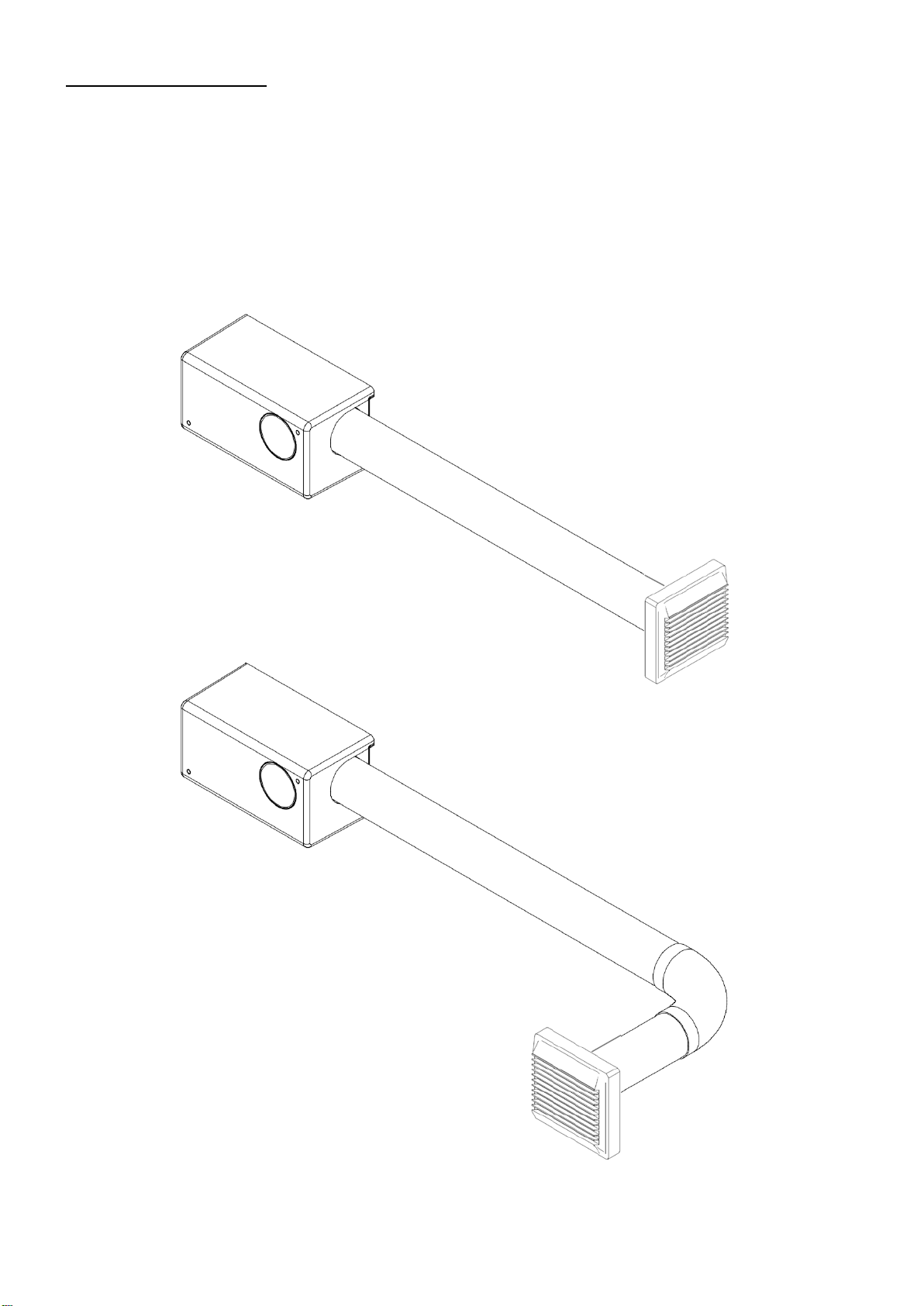
The Unit is a positive input ventilation unit, designed to be installed on a wall of a
dwelling to continually supply filtered fresh air into the building. The system
consists of a fan unit with heater.
The Unit has an adjustable speed settings. These speeds are set during installation;
there are 4 pre-set speeds or an option allowing the speeds to be chosen manually from
10 L/s - 30 L/s. The Unit uses a sensor to monitor the supply temperature into the
room. If the ambient room temperature exceeds 27°C (adjustable during commissioning),
the unit will automatically switch to standby (no airflow), unless installed in radon
mode (selectable during commissioning).
All models are supplied with a heater; the element is activated by default when the
supply air temperature drops below the adjustable threshold. The heater will try and
maintain the supply air temperature at the threshold temperature. The threshold
temperature can be adjusted during commissioning.
The unit also incorporates a data logging function. This function will display total
runtime of system, energy consumption of the fan and energy consumption of the heater.
This data is resettable (when in data logging menu, hold the + and – button for 15
seconds until you see the word “RESET” on the display).
SAFETY AND GUIDANCE NOTES
IMPORTANT: READ THESE INSTRUCTIONS BEFORE
COMMENCING THE INSTALLATION
1.
DO NOT install this product in areas where the following may be
present or occur:
1.1.
Excessive oil or a grease laden atmosphere.
1.2.
Corrosive or flammable gases, liquids or vapours.
1.3.
Ambient temperatures higher than 40°C or less than -10°C.
1.4.
Possible obstructions which would hinder access or removal
of the Fan.
1.5.
Relative humidity above 90%
1.6.
Sudden ductwork bends or transformations close to the Unit.
1.7.
To achieve optimal airflow, the unit should be mounted 1.8m
from floor level.
2.
All wiring to be in accordance with the current I.E.E.
Regulations, or the appropriate standards of your country and MUST
be installed by a suitably qualified person.
3.
The fan must be provided with a 3A fused, isolator switch capable
of disconnecting all poles, having a contact separation of at
least 3mm.
4.
Ensure that the mains supply (voltage, frequency, and phase)
complies with the fan’s rating label.
5.
The fan should not be used where it is liable to be subjected to
direct water spray.
6.
This appliance can be used by children aged from 8 years and above
and persons with reduced physical, sensory or mental capabilities
or lack of experience and knowledge if they have been given
supervision or instruction concerning use of the appliance in a

3
safe way and understand the hazards involved. Children shall not
play with the appliance. Cleaning and user maintenance shall not
be made by children without supervision.
7.
Precautions must be taken to avoid the back-flow of gases into the
room from the open flue of gas or other fuel-burning appliances.
8.
Children of less than 3 years should be kept away unless
continuously supervised.
9.
Children aged from 3 to 8 years shall only switch on/off the
appliance provided the unit is installed as intended for normal
operation and they have been given supervision or instruction
concerning safe use of the appliance and understand the hazards
involved.
10.
Children aged 3 to 8 shall not plug in, regulate and clean the
appliance or perform user maintenance.
Caution - some parts of this product can become very hot and cause
burns. Particular attention has to be given where children and
vulnerable people are present.
UNIT SIZE
UNIT MOUNTING
Unit to be mounted horizontally
To achieve optimal airflow, the unit should be mounted 1.8m from floor level.
If this is not possible, installation lower than 1.8m is safe and acceptable.

4
TYPICAL INSTALLATIONS
ABS COVER ONLY
See Inlet Options 1 or 2 for Install, page 8.
1. Insulate all ducting running from atmosphere and any ducting that passes through
an unheated space.
Choose either a side or rear inlet position for the unit.
FLEX DUCT INSTALL
1. Securely connect the flexible ducting to the unit’s spigot, using worm-
drive clip or cable ties. See page 12, Outlet Option 3 for Install
details.
2. Extend the flexible ducting to its full length, to prevent moisture
collection & avoids airflow issues.
3. Secure diffuser to flexible ducting, using worm-drive clip or cable ties.
The total length of flexible duct in the system (Inlet and outlet) should
not exceed 2m. For the best performace and lowest noise, rigid ducting
should be used where possible.
The diagram below is simplified, the inlet ducts, duct cover and clips are not shown,
your installation may vary

5
RIGID DUCT INSTALL
1. Securely connect the rigid ducting to the unit’s spigot, using a suitable
adhesive. See Outlet Option 3 for Install, page 11.
2. Secure diffuser to the rigid ducting, using a suitable adhesive.
3. The total length of rigid duct in the system (Inlet and outlet) should
not exceed 2.5m, with a maximum of two 90° bends.
The diagrams below are simplified, the inlet ducts, duct cover and clips are not
shown, your installation may vary.

6
INSTALLATION
The Unit is wall-mounted using the bracket and fixings supplied (or other suitable
fasteners).
Ensure there is sufficient space around the unit’s base plate, when installing, to
allow fitting & removal of the cover for servicing & maintenance. (See image below).
The wall should have sufficient strength to support the unit.
Take into consideration the routing of the cable and the ducting that must be fitted
to the inlet spigot.
The unit can be mounted vertically or horizontally on a vertical wall.
IMPORTANT

7
Hand tighten these 2
screws, when fitting the
scroll assembly.
Feed power supply (and
optional Heater Switch cable)
through Base plate or bottom
left hand side of unit, then
through the rear of the foam
before securing unit.

8
INLET OPTIONS
OPTION - 1
OPTION - 2
If installing the unit with the air supply
coming through the rear, the metal
plate cut-out will need to be removed from
base plate and the rear foam
case will need to be cut-out before mounting.
See next page for details.

9
Base Plate
Rear Foam
Snip the three tabs to remove the insert
Using the centre mark, cut through the foam housing using a hole

10
OUTLET OPTIONS
OPTION - 1

11
OUTLET OPTIONS
OPTION - 2

12
OUTLET OPTIONS
OPTION - 3

13
FILTER INSTALLATION
Please make sure the filter is fitted correctly and retained on top of the scroll.
This will ensure that all the fresh air entering the dwelling has passed through the
filter first.
Slide filter on top of scroll
Push filter over retaining clip to
secure it in place.

14
Cover Plates – Grille & Blanking
When using the cover plates on the front of the unit, care must be taken when snapping
them free.
Only the cover plate that is being used in the front of the housing needs to be
modified.
It is recommended to install the grille facing towards the ceiling to minimise the
effect of cold draughts

15
WIRING
A means for disconnection must be incorporated, in the fixed wiring in accordance with
the wiring regulations.
WARNING: THE POSITIVE VENTILATION UNIT AND ANCILLARY
CONTROL EQUIPMENT MUST BE ISOLATED FROM THE POWER SUPPLY
DURING THE INSTALLATION / OR MAINTENANCE.
Mains supply voltages (220-240V AC) are present in this equipment which may cause
death or serious injury by electric shock. Only a qualified electrician or installer
should connect the power supply to this unit.
The Unit is designed for operation from a single-phase alternating current source
(220-240V AC).
The unit must be connected with a suitable lead via a 3A switched fused spur.
It should be capable of disconnecting all poles, having a contact separation of at
least 3mm.
OPTION – 1 (STANDARD WIRING)
OPTION – 2 (HEATER SWITCH WIRING) (Accessory - Pg.19)

16
Univers 45 Light
In order to have the product switch off in
the event of a fire it must be wired using
a smoke alarm with a relay system.
Use diagram as a reference and refer to
the instructions provided by the
manufacturer of the smoke alarm and relay
in order to wire the unit correctly.
Ensure the relay works correctly by
testing the fire alarm; the unit should
switch off when the alarm is sounding.
START UP SEQUENCE
When the unit is switched on it will first run through a period of system checks.
During this time the display will show various system parameters before the fan motor
starts. After 20 seconds the product will be ready for commissioning.
COMMISSIONING
Accessing the Commissioning Menu
If the fan is powered and the display is not lit, then press any button to access the
menu. After 30 seconds without menu activity the display will switch off, any changes
to the settings will then be applied.
There are three buttons on the front of the unit:
The + button is used to increase the value of a setting, the – button is used to
reduce the value of a setting and the Mode button moves to the next menu item.
+
-
MODE
Use this cable clamp on scroll to
secure mains power cable.
Use this cable clamp on scroll to
secure optional Heater Switch
cable.
FOR REFERENCE ONLY
PIV
UNIT

17
Lock feature
The lock feature will prevent the unit from being adjusted after commissioning as a
pass code is required to access the menu. This can be set in the menu to any 3 digit
hexadecimal combination.
If the lock feature is enabled; when a button is pressed the display will show, – – –.
At this point enter the three digit code by first pressing + or – until the first
digit is correct then press MODE to move to the next digit. Repeat until the code is
entered and press MODE to enter the commissioning menu. If the code is entered
incorrectly, wait until the screen switches off then press any button to begin again.
Air filter
The Unit is provided with an ISO Coarse (G4) filters which are suitable for removing
airborne contaminants such as pollen and dust.
Where improved filtration is required optional ISO ePM2.5 (F7) filters can be used.
These filters are effective at removing finer particles such as particulate emissions
from diesel engines. In urban areas close to main roads, ISO ePM2.5 (F7) filters are
advisable in order to ensure the supply air is clear of these particles which are
potentially harmful to health.
Where ISO ePM2.5 (F7) filters are fitted, please ensure the flow rate of the fan is as
expected. F7 filters cause extra system resistance so it may be necessary to increase
the fan speed to compensate.
Commissioning Menu Structure
* This setting rotates the display only; the buttons retain their original function.
For example; the mode button is on the right when in normal rotation and on the left
when the screen is rotated and looking at the fan so the display is correctly
orientated.
** Display: unl
Description: menu lock on or off. When locked a code is required to access the menu
Options: unl – unlocked Loc – Locked.
*** Display: cod
Description: Set the menu lock code. This is a 3 digit hexadecimal code, set between 0
- F.
Display text
Installation Option
Selections
rot-rot
Display rotation*
rot-rot = Default
r-y rot =
Rotated 180
o
d-n / d-y
Ducted Yes/No
d-n = Default
d-y = Yes
p-n / p-y
Preset Speed No/Yes
p-n = No
p-y = Yes
b01 - b04
Number of Bedrooms
1-4
b01/02/03/04 =
Range
b01 = Default
t10 – t30
Flowrate 10-30 L/s
t10 – t30 L/s
c05 – c20
Heater setpoint 5-
20°C
c05-c20°C
c05 = Default
F.G4 – F.F7
Filter fitted G4/F7
G4 = Default
F7 = Optional
r-n / r-y
Radon mode No/Yes
r-n = Default
r-y = Yes
t26 – t35
Summertime cutoff
26-35°C
t26 – t35 = Range
t27 = Default
bst
Boost Overrun Time
0, 1, 2, 4, 8 hr
0 = Default
c-n / c-y
Comfort Mode Yes/No
c-n = No
c-y = Yes
unl / loc
Lock feature
On/Off**
unl = unlocked
Ioc = Locked
cod
Lock code***
Set between 0 - F

18
Options: press up or down to start choosing the first digit then press mode to set and
move to the next digit. Repeat to set the other two digits. Default override code is
999.
For most installs the standard features allow for ample adjustability, however in some
install situations the advanced features will improve the unit’s performance or
acceptability.
Radon mode keeps the fan running even at high temperatures to prevent the build-up of
dangerous radon gas in the property. If this is not required it is recommended not to
use this setting.
Speed Settings
The unit will run constantly at the set speed, with the following exceptions.
If the ambient inlet temperature exceeds the Summertime Cut-off temperature 27°C
(default), the Unit automatically switches to standby (no airflow). If Radon Mode in
enabled, the Unit will continue to run beyond the normal threshold temperatures.
Purge/Boost-Mode: Boost-mode is initiated when an LS signal is detected. The fan speed
will then be set to maximum until the LS signal is removed.
The speed settings on the Unit are fully adjustable between 10 L/s and 30 L/s via the
manual speed setting option. Alternatively there are 4 Pre-set speeds, the speed
settings relate to the number of bedrooms with, for example, setting b03 being for a
three bedroom dwelling. For the approximate flow rates at each setting see table
below.
The Unit must be set to provide adequate ventilation according to Part F of the
building regulations.
Ducted Mode – No Ducted Mode – Yes
When No Ducting is used When Ducting is used
The table shows a set up representative of a good, low resistance install. When F7
filters and/or a long duct run are used it may be necessary to use the manual speed
selection to meet the required flow rate.
It is the responsibility of the installer to ensure that appropriate speeds are
selected.
When ducted mode is enabled, the fan speed is increased to compensate for the
additional restriction caused by the fitted ducting.
COMFORT MODE
The comfort mode feature offsets/delays the boost when LS has been activated until
after LS has been deactivated (up to a maximum of 20 minutes). Therefore reducing any
nuisance noise until after the user has left the room.
When LS is deactivated, fan will run at boost mode for the length of time the LS was
present (up to a maximum of 20 minutes) plus the set overrun time.
If the Boost Switch was activated for less than 3 minutes, no boost will occur to
prevent nuisance activations.
If the Boost Switch is still connected after 20 minutes, the fan will boost anyway.
Once the Boost is disconnected, the fan will run for only 20 minutes plus the set
overrun timeout.
No.
Bedrooms
L/s
Power (W)
b01
13
3.5W
b02
17
6W
b03
21
9W
b04
25
14W
No.
Bedrooms
L/s
Power (W)
b01
13
5W
b02
17
8W
b03
21
12W
b04
25
18W

19
SERVICING AND MAINTENANCE.
WARNING: THE POSITIVE VENTILATIION UNIT AND ANCILLARY
CONTROL EQUIPMENT MUST BE ISOLATED FROM THE POWER SUPPLY
DURING THE INSTALLATION / OR MAINTENANCE.
The fan motor uses sealed ball bearings, and does not require further lubrication.
Apart from filter change the Unit contains no user serviceable parts.
Under normal conditions; i.e. away from main roads and industrial areas it is
recommended that the filter is checked annually and cleaned or replaced as necessary.
Otherwise change as required.
The filter may be gently cleaned with a vacuum cleaner or washed in a soapy water
solution and allowed to air dry before re-fitting. Do not dry the filter in a tumble
dryer.
When re-fitting make sure that the filter is fitted correctly. This will ensure that
all the fresh air entering the dwelling has passed through the filter first.
Accessing Data Logger Menu
To access the menu of data that the unit stores press and hold the mode button for 5
seconds. The menu structure is shown below, press mode to move to the next item:
Data Examples
Text scrolling from right to left
In this example the display is showing a total run time of 1 year and 237
days.
Text scrolling from right to left
In this example the display is showing 34Wh of energy consumption in the
previous 24h.
To exit the menu press MODE for 5 seconds or wait for the screen to switch
off.
Display text
Description
tot run 00y 00d
Total run time in years and days
Fan EnErgy 00(Wh)
Energy used in last 24 hours displayed in Wh
Heat EnErgy 00(kWh)
Energy used in last 24 hours displayed in kWh
tot EnErgy 00.0
Total Energy used displayed in kWh

20
Spares and accessories available for the Air+ Wall:
Spares and Accessories
Part Number
ABS COVER
479844
SILENCER KIT
479857
ACOUSTIC FLEXI DUCT
443273
ROUND TO RECTANGLE ADAPTOR - ∅105mm to 55x110mm
400740
REPLACEMENT 3 BUTTON SCROLL ASSY
479859
FILTER ISO Coarse (G4)
FIL10
FILTER ISO ePM2.5 (F7)
FIL2.5
WALL FITTING KIT - WHITE
ESG100WALLW
WALL FITTING KIT - BROWN
ESG100WALLB
HEATER SWITCH
479982
Disposal
This product should not be disposed of with household waste. Please recycle
where Facilities exist. Check with your local authority for recycling
advice.
EU Authorised Representative:
AIRTECH ENVIRONMENTAL SYSTEMS
STATHE ROAD, BURROWBRIDGE, SOMERSET, TA7 0RY
Tel : 0800 378 017
479637 G 0124
This manual suits for next models
1
Table of contents
Other AirTech Fan manuals
Popular Fan manuals by other brands

Multikomplex
Multikomplex Aerauliqa QMF installation manual

Bionaire
Bionaire BSF1612M instruction manual

Domestic
Domestic ecoair Halo manual

HIRED-HAND
HIRED-HAND MEGA-FLOW MF-24O-D-S-SE Series quick start guide

Jimmy
Jimmy JF41 Pro user manual

Siemens
Siemens LR97CAQ50B User manual and installation instructiions