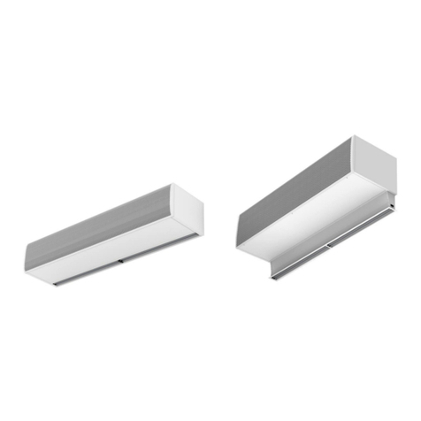
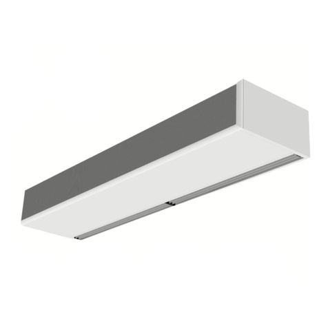
Airtecnics OPTIMA User manual

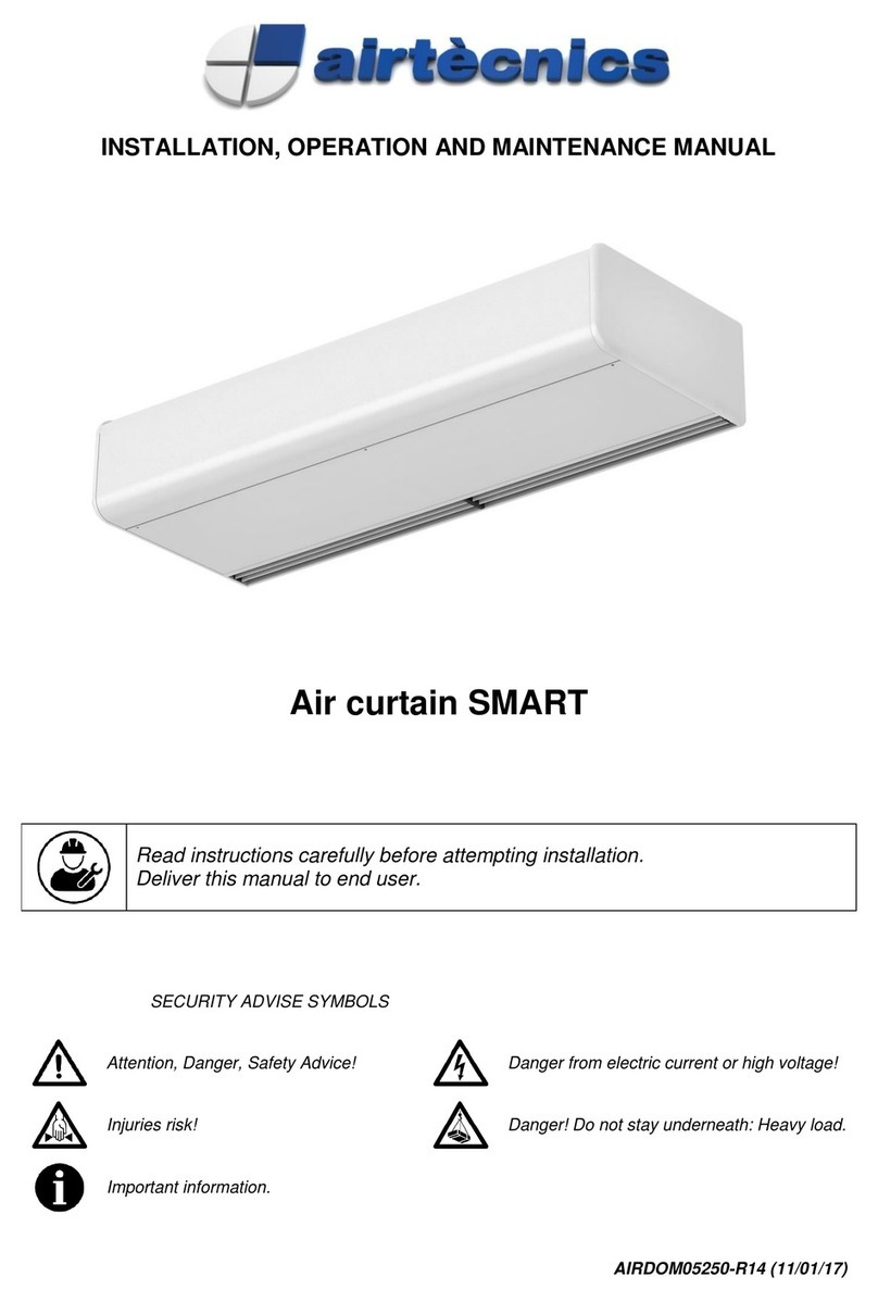
INSTALLATION, OPERATION AND MAINTENANCE MANUAL
Air Curtain OPTIMA WIRELESS
Please, read these instructions carefully before attempting installation
SECURITY ADVISE SYMBOLS
Attention, Danger, Safety Advice!
Danger from electric current or high voltage!
Injuries risk!
Danger! Do not stay underneath: Heavy load.
Important information.
AIRDOM05451-R13 (29/06/16)

2
INDEX
CONNECTION DIAGRAM..................................................................................................................................3
INSTALLATION..................................................................................................................................................4
Power Supply..................................................................................................................................................4
Fixing...............................................................................................................................................................4
Electrical elements..........................................................................................................................................4
STORAGE AND TRANSPORT..........................................................................................................................5
WORKING INSTRUCTIONS..............................................................................................................................5
Control PCBoard characteristics.....................................................................................................................5
Controller’s common characteristics...............................................................................................................5
Common characteristics to all controllers for electrical heated air curtains....................................................5
Remote control characteristics........................................................................................................................6
WIRING DIAGRAMS..........................................................................................................................................6
DATASHEET....................................................................................................................................................14
MAINTENANCE INSTRUCTIONS ...................................................................................................................15
External cleaning...........................................................................................................................................15
Internal cleaning............................................................................................................................................15
REPAIRS AND REPLACEMENTS...................................................................................................................16
Motor or turbine replacement........................................................................................................................16
Fuse replacement .........................................................................................................................................16
Plate replacement.........................................................................................................................................16
Heater replacement.......................................................................................................................................17
Heat exchanger replacement........................................................................................................................17
ACCESSORIES................................................................................................................................................17
DECLARATION OF CONFORMITY.................................................................................................................18
Air curtain identification.................................................................................................................................19
GUARANTEE ...................................................................................................................................................19

3
CONNECTION DIAGRAM

4
INSTALLATION
Valid for models: Optima Wireless
MAX. Maximum recommended height, MIN. Minimum recommended distance
(**) Removable covers
Minimum recommended distance between the inlet grille and any obstacle is of 200mm.
Power Supply
To connect the power supply there is a black connection box outside the air curtain (located on top).
For an ambient air, just connect the single phase 230Vx1.
In case of an air curtain with electrical heating we will also connect the three phase 400Vx3 of the electrical
element. Optionally under request the power supply of the electrical element can be single phase 230Vx1
depending on each model (special wiring diagram will be enclosed).
Fixing
Units are provided of several external suspension points, depending on the weight and length of each model
(see exact situation of the points at the air curtains characteristics page).
The fixing of the air curtain should be managed according to the weights of each unit shown on the technical
data page. The installation can be made through threaded rods, cable tensors or other supports.
See available supports in the accessories section.
Electrical elements
The heater element has 3 or 6 resistances bars (depending on the model) that combined give 2 power
stages. The control is managed by 2 PRBEO of 2 and 1 bars (in case of 3 resistances), or 4 and 2 bars (in
case of 6 resistances).
Installation work, connection, disconnection, electrical wiring, mechanical maintenance
and service must be done by qualified people observing these instructions and in
accordance with all applicable norms and standards.
If the unit is operated with additional controller, please consider its specific instructions.
There is no need to open the service door to connect the air curtain. All connections
(power supply, control, water pipes when existing) and fixations are external. They are
placed on top of the units. See how to open service door at repairs section.
For safety, the air curtains never have to be stopped by disconnecting them from the
main supply, always through the controller and waiting 10 minutes at least to disconnect
the main supply. In case to not follow these instructions, the internal parts of the air
curtain can be damaged.

5
STORAGE AND TRANSPORT
Attention! Heavy load.
Do not step underneath hanging load during the transport or assembly.
Store in a dry place and weather protected in its original packaging. In case the packing is opened, cover the
air curtain to protect it from dust. Do not step or put heavy load over the package to avoid damages to the
material. Store temperatures are between -20ºC and +40ºC.
When carrying material, make sure it is not damaged by the forklift (fork penetration in the packaging).
Please see the Packaging instructions.
WORKING INSTRUCTIONS
Control PCBoard characteristics
The PCBoard relays adjust the 2 ventilation and heating speed in case of electrical heated air curtains.
Controller’s common characteristics
Controllers: There is an inbuilt keypad controller placed in the service door, which allows to switch
the fan speed and the power stage of the electrical element.
2 ventilation speed.
Remote control: All the standard controllers have an IR receiver that works by infrared.
Unheated air curtains controller
Common characteristics to all controllers for electrical heated air curtains
2 speed system with 2 different Fan Speed and Heating Stages (H1, H2).
Controller for electrical heated air curtains
Two heating stages: On the first heating stage a green LED turns on, and on the second stage the
LED becomes red.
Thermal Limitation: to work the heating there must be any ventilation speed selected, what allow us
to choose the maximum heating capacity with the minimum ventilation.
Time of delay: When the equipment is stopped, and it has been working, the electrical heater is still
heating during several minutes by thermal inertia with the consequent increase of internal
temperature. In order to avoid internal damages by overheating, when we stop the air curtain, it
keeps turned on for a period of time.
The air speed and the heating stage are indicated by a lighted LED while the safety function is indicated by a
flashing LED.
For safety, the air curtains never have to be stopped by disconnecting them from the main
supply, always through the controller and wait for 10 minutes at least to disconnect the
main supply. In case to not follow these instructions, the internal parts of the air curtain
can be damaged.

6
Remote control characteristics
WIRING DIAGRAMS
Following wiring diagrams are enclosed:
For the following models: OPTIMA WIRELESS 1000 - 1500
Only air with standard controller. Diagram: AIRDOE07900
Electrical 400Vx3 1000E6kW - 1500E6-9kW with standard controller. Diagram: AIRDOE07910
Electrical 230Vx1 1000 - 1500E6kW with standard controller. Diagram: AIRDOE07920
Electrical 230Vx1 1500E9kW with standard controller. Diagram: AIRDOE07925
For the following models: OPTIMA WIRELESS 2000
Only air with standard controller. Diagram: AIRDOE07950
Electrical 400Vx3 2000E with standard controller. Diagram: AIRDOE07960
Electrical 230Vx1 2000E with standard controller. Diagram: AIRDOE07965
In case you need to connect the equipment to a PLC, the corresponding wiring diagrams will be supplied.
In electrical heated air curtains are
used to raise and lower the heating.
In water heated, is used to turn ON
and OFF the electrovalve.
Not used with unheated air curtains.
Works with batteries
t
yp
e AAA/LR03
Increase or decrease
the fans speed
Infrared System Turn ON and OFF the Air Curtain

7

8

9

10

11

12

13

14
DATASHEET

15
MAINTENANCE INSTRUCTIONS
For safety, before any cleaning, disconnect power supply using the controller.
It is forbidden to open the service door (risk of electrical discharge and being
trapped in fans).
Service and maintenance should be done only by introduced and qualified
workers.
Do not use water or steam for cleaning the internal parts and components of
the air curtain.
External cleaning
Air curtains don’t need any kind of maintenance except from the cleaning of the casing and the inlet grille.
It is recommended to weekly clean the inlet grille. It’s important to make sure that the air curtain is OFF,
otherwise the dust mixed with a wet cloth would create a kind of paste that will damage the fan rotor when it
sucks the air.
Annual cleaning of the discharge area (outlet).
The casing of the air curtain should be cleaned with a wet cloth and non-aggressive detergent. Do not use
caustic soap or acids.
The inlet grille prevents the settling of dust and strange objects in the internal elements. It is recommended to
check periodically that the inlet grille is free of any object that could interfere the air entrance (plastic bags,
papers, etc.).
In case of a micro drilled inlet grille (it has filter functions to prevent the entrance of dust to the internal
elements) use a vacuum cleaner with a soft brush in order to avoid any damages in the micro drilled grille.
We recommend cleaning the grille every week (depending on the amount of the incoming air dust).
Internal cleaning
In models with micro drilled grille is recommended to clean the inside of the unit with a vacuum at least once
every two years (*), best before the winter season, with qualified staff.
(*) These periods are indicative, depending on the ambient conditions of every installation.
In places with a high number of particles in suspension is desirable to increase the frequency of the internal
cleaning (including the city centers, near construction sites, etc.).

16
REPAIRS AND REPLACEMENTS
To open the service door, follow these steps:
Remove the lateral
Lever softly between the grille and the door.
Motor or turbine replacement
Before the motor replacement, advise people that there is work in progress.
Release the connector of the motor. Release the fixation screw of the impeller (Allen L hex key 2.5mm)
through the discharge opening.
Remove motor by loosening the fixation screws. Install the replacement motor following the process in
reverse order, making sure that the motor and the turbine fit perfectly, the turbine screw must fit in with the
flat part of the motor axle.
Fuse replacement
Before the replacement, inform people that there is work in progress,
disconnect main supply, make sure that the unit is without tension and that
the fans are stopped.
Open the service door and unplug the visible cable from the plate and the
condenser. The fuse is protected by a plastic box. Pull up the plastic box
with the help of a screwdriver and replace the fuse.
Plate replacement
Open the service door and unplug the visible cables from the plate and the condenser.
Installation and electrical connections must be done by qualified workers and following
these instructions.
Before any repairs are undertaken, please:
Inform people that there is work in progress.
Disconnect the power supply and protect the thermal magnet (so nobody can restart
it accidentally).
Make sure there is no tension in the air curtain.
Make sure the fans are stopped.
Use only original spare parts.

17
Heater replacement
Before the replacement, inform people that there is work in progress, disconnect main supply, make sure that
the unit is without tension and that the fans are stopped. Before proceeding to unfasten the heater fixing
screws, we must:
Electrical Heaters: Disconnect the power supply from the electrical element.
Heat exchanger replacement
Before change of heater, inform people that there is work in progress, stop the air curtain through the inbuilt
controller and disconnect main supply. Make sure that the unit is without tension and the fans are stationary.
Before removing the screws that fix the heater, we have to:
Once removed the screws we will proceed to remove the water coil or electrical element using gloves to
avoid any cut.
ACCESSORIES
Supports, vibration dampers, etc. depending on the model.
1. Disconnect the power supply of
the battery: remove the screw-earth
of the connection box and
disassemble from the equipment.
2. Disconnect the cables 2, 3
and 4 of the connections box. 3. Disconnect the connector B1.
4. When we have the heater ready, we proceed to remove the fixation screws of the battery to remove it.
To assemble the new heater follow the same process in reverse order.

18
DECLARATION OF CONFORMITY

19
Air curtain identification
Each air curtain is identified by a unique serial number
printed in a label located inside the door service.
There is also indicated the model and their technical
characteristics (flow, fans technical characteristics and
power heating).
It is indispensable to have this number to facilitate
possible replacements or technical information of the
air curtain in question.
If you detect some error in this manual, we’ll be
pleased to receive your feedback, it helps us to
improve even more.
Airtècnics reserves the right to modify some of the
specifications in this manual.
GUARANTEE
Your air curtain is guaranteed for a period of one year from the date of purchase. We will adjust, repair or
replace at our discretion from our warehouse any defect, system failure or part found to be defective. The
assembly cost out of our warehouse is at buyer expense. The products that, in our eyes, have been
inadequately used, incorrectly manipulated, improperly installed, connected to different nominal tensions,
modified, repaired by non-authorized workers or that have suffered damages during transport are totally
excluded from the guarantee.
To validate the guarantee it should be correctly filled and enclosed with the invoice that vouches for the buying date. If it is manipulated,
it will lose all validity.
It is the buyer’s responsibility to take the necessary safety measures because in case of a failure or mistake in one of one our products,
no damages to third parties, sets or installations will occur.
Guarantee draft
Air curtains data:
Model: ............................................... Series number: ........................................................
Invoice date: ..................................... Invoice number: .......................................................
Buyer data:
Name: ................................................................................................................................................................
Address: ............................................................................................................................................................
Country: ………………………… Phone: ............................. Fax: ........................................................
Seller data:
Name: ................................................................................................................................................................
Address: ............................................................................................................................................................
Country: ………………………… Phone: .............................. Fax: ........................................................
Buyer signature and stamp Seller signature and stamp
Other manuals for OPTIMA
1
Table of contents
Other Airtecnics Heater manuals