Airtecnics SMART M 1000 A User manual

INSTALLATION, OPERATION AND MAINTENANCE MANUAL
Air curtain SMART
Read instructions carefully before attempting installation.
Deliver this manual to end user.
SECURITY ADVISE SYMBOLS
Attention, Danger, Safety Advice!
Danger from electric current or high voltage!
Injuries risk!
Danger! Do not stay underneath: Heavy load.
Important information.
AIRDOM05250-R14 (11/01/17)

(2) Manual - Air curtain - SMART
INDEX
CONNECTION DIAGRAM..................................................................................................................................3
INSTALLATION..................................................................................................................................................4
Power Supply..................................................................................................................................................5
PCBoard and Control......................................................................................................................................5
Fixing...............................................................................................................................................................5
Water coils ......................................................................................................................................................5
Electrical elements..........................................................................................................................................5
STORAGE AND TRANSPORT ..........................................................................................................................6
WORKING INSTRUCTIONS..............................................................................................................................6
Control PCBoard characteristics.....................................................................................................................6
Controller’s common characteristics ...............................................................................................................6
Common characteristics to all controllers for water heated air curtains .........................................................7
Common characteristics to all controllers for electrical heated air curtains....................................................7
Special controllers...........................................................................................................................................8
Remote control characteristics........................................................................................................................8
WIRING DIAGRAMS..........................................................................................................................................8
DATASHEET ....................................................................................................................................................13
MAINTENANCE INSTRUCTIONS ...................................................................................................................15
External cleaning...........................................................................................................................................15
Internal cleaning............................................................................................................................................15
REPAIRS AND REPLACEMENTS...................................................................................................................16
Fan replacement...........................................................................................................................................17
Fuse and PCB replacement..........................................................................................................................17
Heater replacement.......................................................................................................................................18
FAILURES AND SOLUTIONS..........................................................................................................................19
ACCESSORIES................................................................................................................................................20
DECLARATION OF CONFORMITY.................................................................................................................21
Air curtain identification.................................................................................................................................22
GUARANTEE ...................................................................................................................................................22

(3) Manual - Air curtain - SMART
CONNECTION DIAGRAM

(4) Manual - Air curtain - SMART
INSTALLATION
Valid for models: Smart
MAX. Maximum recommended height, MIN. Minimum recommended distance
(*) Minimum distance between the inlet grille and any obstacle is of 15 cm (25 cm to open front panel totally)
(**) Removable covers
Installation work, connection, disconnection, electrical wiring, mechanical
maintenance and service must be done by qualified people observing these
instructions and in accordance with all applicable norms and standards.
If the unit is operated with additional controller, please consider its specific
instructions.
There is no need to open the service door to connect the air curtain. All connections
(power supply, control, water pipes when existing) and fixations are external. They
are placed on top or lateral of the units. See how to open service door at repairs
section.
For safety, the air curtains never have to be stopped by disconnecting them from the
main supply, always through the controller and waiting 10 minutes at least to
disconnect the main supply. In case to not follow these instructions, the internal
parts of the air curtain can be damaged.

(5) Manual - Air curtain - SMART
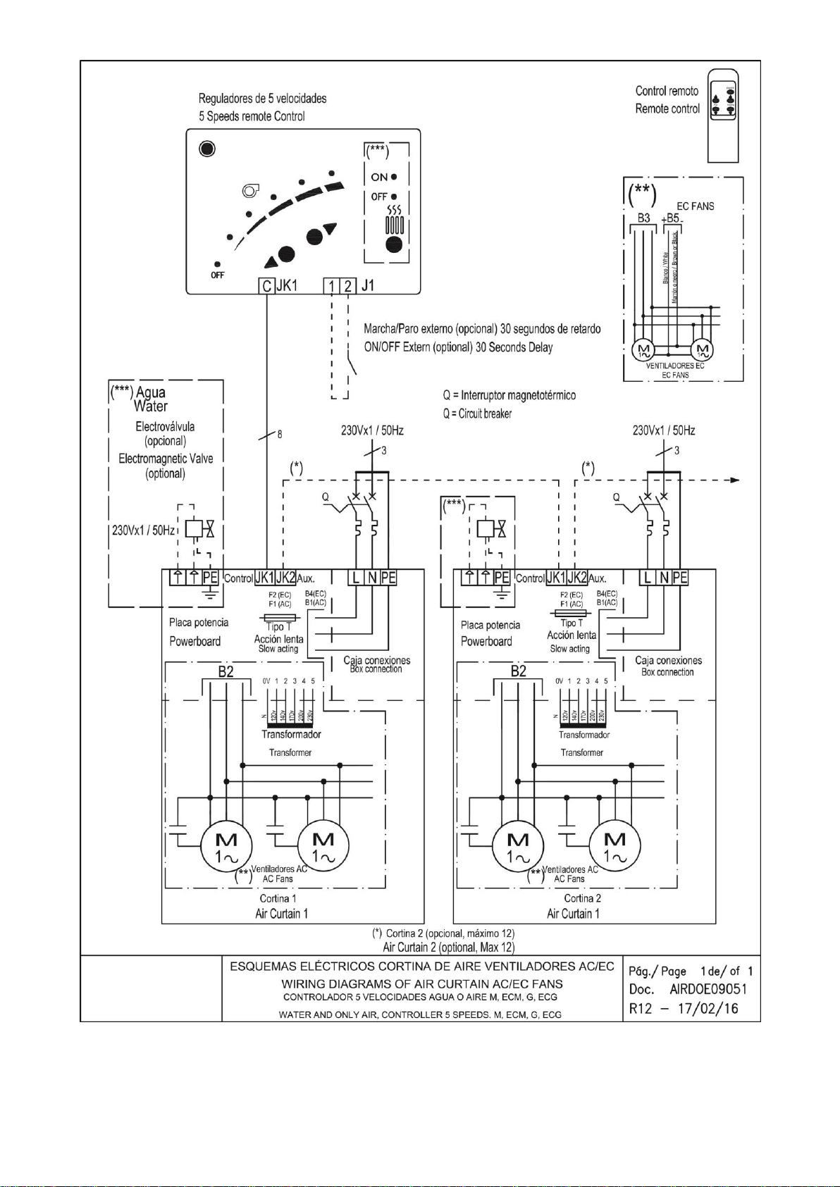
Power Supply
To connect the power supply there is a black connection box outside the air curtain (located on top).
For an ambient air or water heated air curtain just connect the single phase 230Vx1.
In case of an air curtain with electrical heating we will also connect the three phase 400Vx3 of the electrical
element. Optionally under request the power supply of the water coil or electrical element can be three phase
230Vx3 or single phase 230Vx1 depending on each model (special wiring diagram will be enclosed).
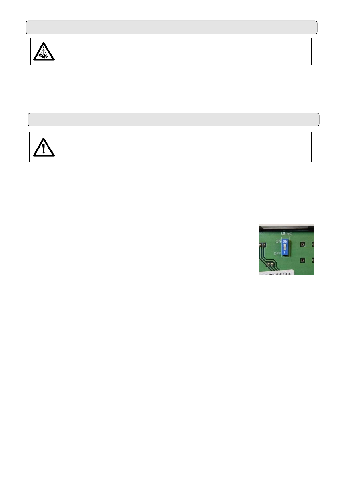
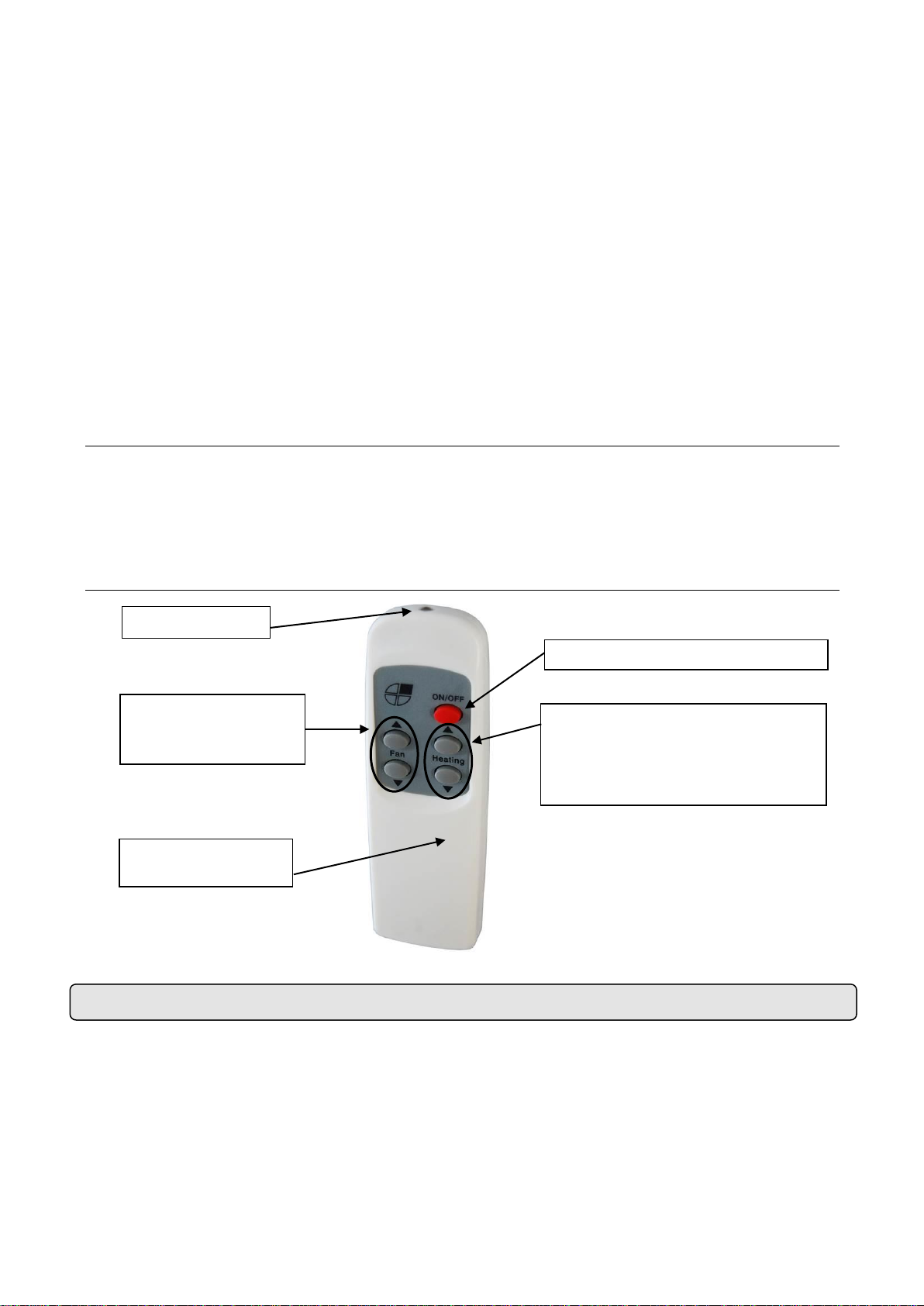
PCBoard and Control
To connect the controller there is a PCBoard (printed circuit) located outside the air curtain (located on top).
There is no need to open the unit to connect it.
Use the 7 meters RJ45 cable supplied with the equipment. The communication between the controller and
the PCB is digital and low-voltage.
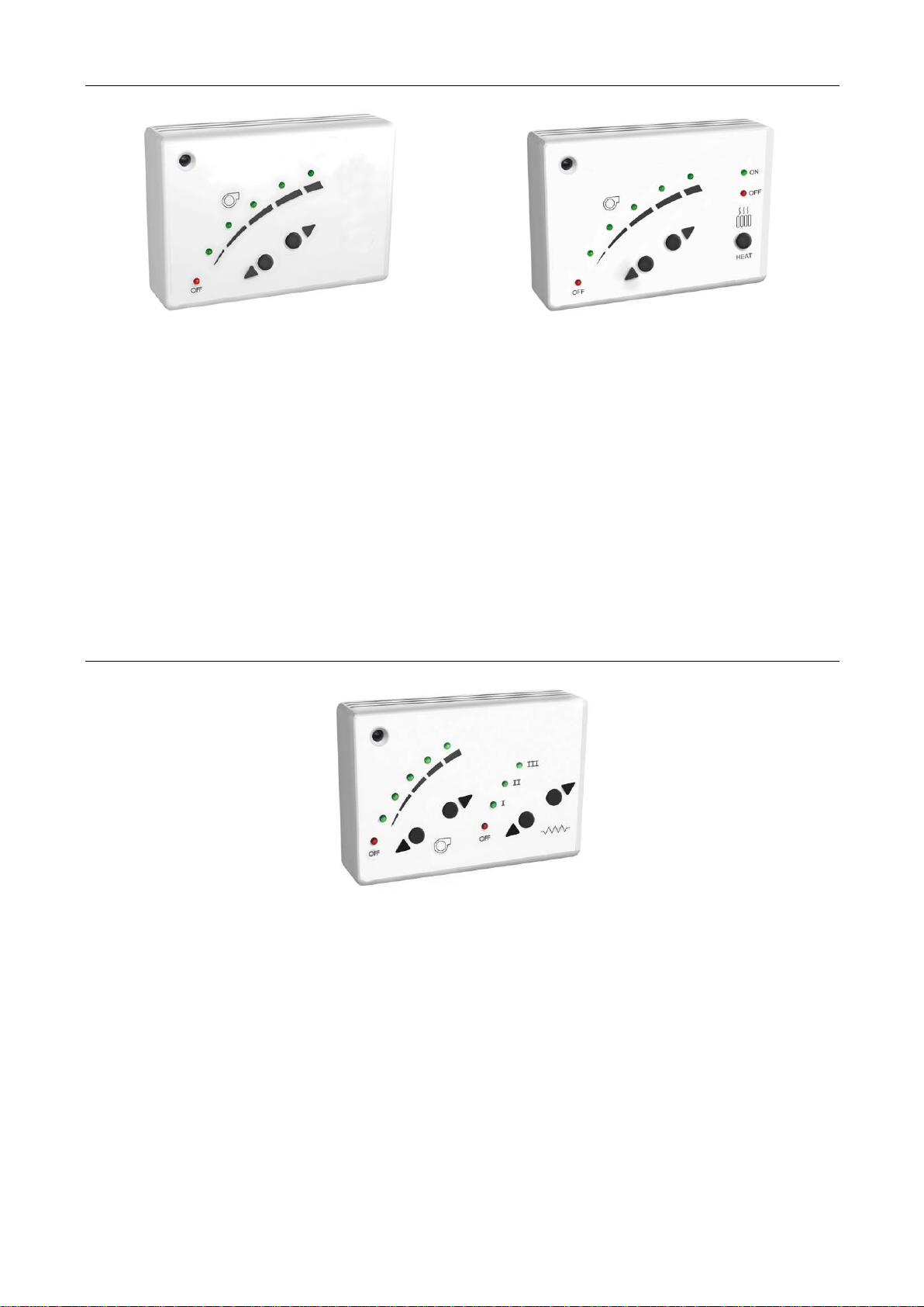
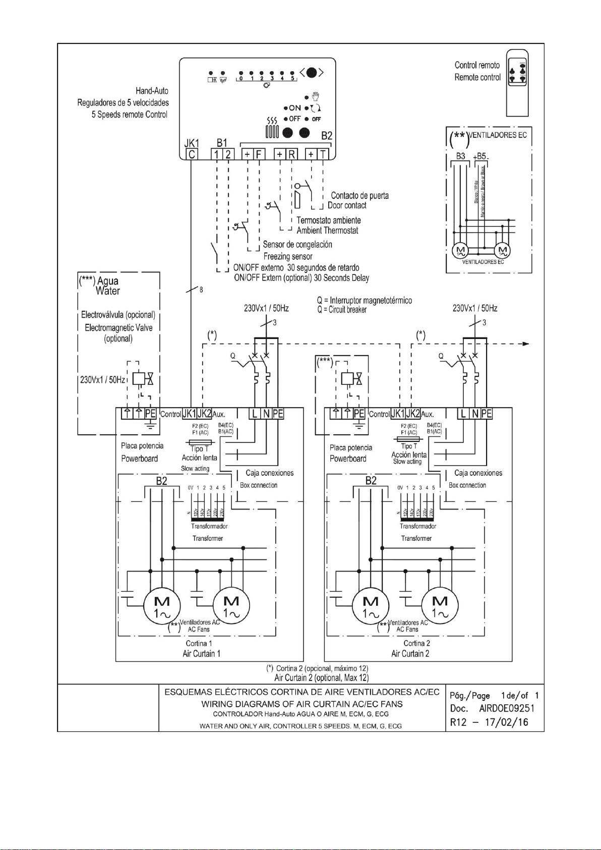
Optionally, there are different accessories and controllers available, to meet every customer needs (Clever
Control, thermostats, hand-auto, door contacts, anti-freezing sensor, supports, valves, etc.).
The new total control for ventilation technology is advanced Clever regulation. Leading the new generation of
air curtains management with maximum control providing maximum energy saving. Clever automatically
adapts the functioning of the air curtain to the entrance climatic conditions in order to keep the comfort and
energy saving. For more information ask for Clever Control manual.
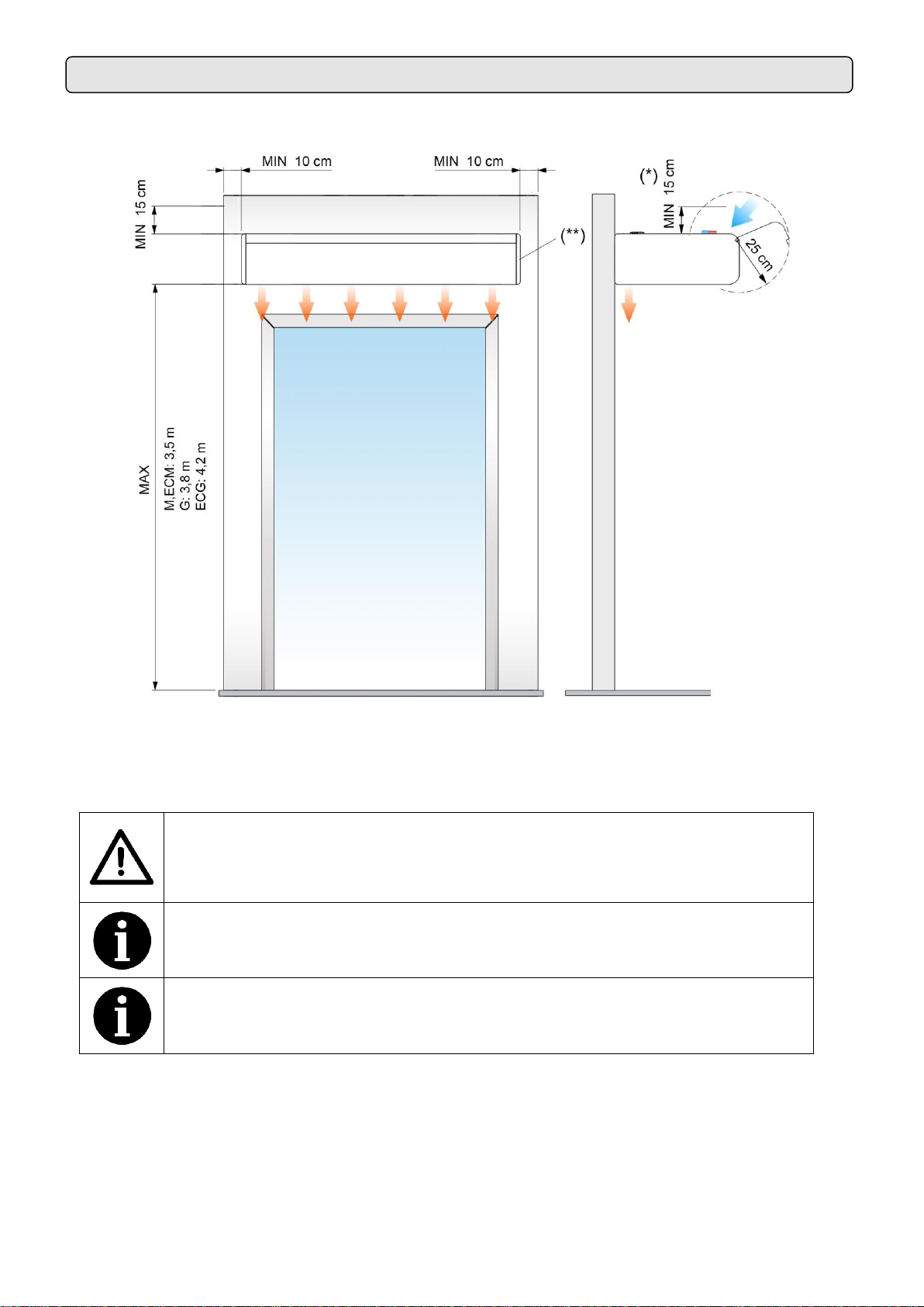
Fixing
Units are provided of several external suspension points, depending on the weight and length of each model
(see exact situation of the points at the air curtains characteristics page).
The fixing of the air curtain should be managed according to the weights of each unit shown on the technical
data page. The installation can be made through threaded rods, cable tensors or other supports. See
available supports in the accessories section.
Water coils
Water heated air curtains have a PCBoard with an output of 230Vx1 to install an electro valve
(open/close water entrance) or any other device.
It is recommended:
Close the hot water circulation (by turning the electrovalve OFF) to avoid fan overheating while the
unit is OFF. Electrovalve is optional.
Install 2 cutoff water valves (supply and return) in order to disassemble the equipment easily.
Install a bleeding valve at the highest part of the water heating circuit.
The ambient temperature should be always over +4ºC, otherwise it will be necessary to provide an anti-frost
protection device.
Water coils have a drainage point placed at the end part of the intake manifolds area.
Some special units are provided with condensation tray prepared to work with cold water. In this case, these
units can’t work at high ventilation speed (depending on model, length and power it will be a speed
limitation). Intake air speed should not be higher than 3m/s because water drops can appear on the outlet.
Electrical elements
The heater element has 9 resistances bars that combined give 2 stages of heating. The control is made by 3
PRBEO when power stage is less than 27kW or by contactors when it is higher than 30kW.
All electrical elements are protected electrically and electronically against overheating (see “Operating
instructions”section).
The electrical controllers have the option to install an external thermostat that turns on/off the heating in order
to control the temperature.
During the first uses scent can be emitted but it disappears in a few days.

(6) Manual - Air curtain - SMART
WORKING INSTRUCTIONS
STORAGE AND TRANSPORT
Attention! Heavy load.
Do not step underneath hanging load during the transport or assembly.
Store in a dry place and weather protected in its original packaging. In case the packing is opened, cover the
air curtain to protect it from dust. Do not step or put heavy load over the package to avoid damages to the
material. Store temperatures are between -20ºC and +40ºC.
When carrying material, make sure it is not damaged by the forklift (fork penetration in the packaging).
Please see the Packaging instructions.
For safety, the air curtains never have to be stopped by disconnecting them from the main
supply, always through the controller and wait for 10 minutes at least to disconnect the
main supply. In case to not follow these instructions, the internal parts of the air curtain
can be damaged.
Control PCBoard characteristics
Fan speed is regulated through the input voltage variation of the fans set. The transformer has 5 output
voltages: 120, 140, 170, 200 and 230 Volts.
Controller’s common characteristics
Controllers: There are several models depending on the customer’s needs (timers, anti-freezing
detectors, thermostats, etc.).
5 ventilation speed.
Memory: When a power shortage happens, it guarantees that the selected
speed will be maintained when the service is re-established. This function can
be connected or disconnected through the switch ON/OFF placed inside the
controller.
RJ45 cable and digital communication: “Plug and Play” easy and fast
connection through RJ45 cable and digital communication between the
controller and the air curtain. This kind of communication is more reliable even
at long distances.
External ON/OFF: Inside the controller we can connect a normally open contact (1, 2) that controls
the ON/OFF of the equipment through any external device, the contact is potential-free. When the
contact is Open, the air curtain is ON. When the contact is closed the air curtain is OFF. It has a 30
seconds delay. It can be used with programmable timer, temperature sensors, fire alarms, PLC, etc.
Remote control: All the standard controllers have an IR receiver that works by infrared.

(7) Manual - Air curtain - SMART
Common characteristics to all controllers for water heated air curtains
Unheated air curtain controller
Warm water heated air curtain controller
Heating ON/OFF: It is possible to activate/deactivate the current of 230Vx1 to the electrovalve to
open/close the water entrance to the coil. This 230Vx1 output connector is placed on top of the
equipment, besides the telephone cable connection of the controller.
How to control an electro-valve with an external thermostat: To control the inlet water to the
battery through a thermostat, we must install it in series with the electro-valve. Thus, when it reaches
the selected temperature, the electro-valve will close.
Safety thermostat: If the internal temperature increases to 60ºC and the first speed being selected,
it automatically turns to the second ventilation speed. It will continue to the maximum speed till the
internal temperature is lower than 50ºC. The emergency operating is indicated by a flashing LED.
If the safety activates too often the cause must be determined. The most probable is that we have to
increase the cleaning of the inlet grill with more regular recurrence.
For example, an obstruction in the inlet grill, the inactive motor or a too high ambient temperature in
an installation with no ambient thermostat or a water temperature of the water coil over 80ºC would
increase automatically the speed fan. It also avoids that the expelled air by the air curtain is over
60ºC (too high temperature sensation for people).
Common characteristics to all controllers for electrical heated air curtains
Equipment of five ventilation speed and three different heating powers (C1, C2, C3= [C1 + C2]).
3 Heating powers: C1=1/3 Total, C2=2/3 Total, C3=C1+C2=Total.
Limited heating powers: For safety reasons of the equipment, the heating power is limited by the
ventilation speed that we had selected, the following way:
Selected speed Max. heating power that can be selected
V1 Stage 1 heating.
V2 Stage 2 heating.
V3 Stage 2 heating.
V4 Stage 3 heating (stage 1 + stage 2).
V5 Stage 3 heating (stage 1 + stage 2).
Thermostat of delay: When the equipment is stopped, and the heating has been working, there is
an increase in temperature (by inertia) inside the equipment that could damage it. In order to avoid
internal damages by overheating, when we stop the curtain and the internal temperature is over
50ºC, there is a delay thermostat having the function to turn on again the fans automatically with
maximum speed till the temperature goes under 50ºC. This safety operating is indicated with a
flashing green LED.

(8) Manual - Air curtain - SMART
WIRING DIAGRAMS
Safety thermostat: When the air curtain operates with heating and the internal temperature
increases over 60ºC, a safety function activates: The air curtain increases one speed every two
minutes till it reaches the maximum speed. After, it will start decreasing 1 heating stage till it stops. In
case that after 2 minutes the situation persists, the heating will block. To unblock it, we must
manually reset by disconnecting from the main supply. If in any moment the temperature decreases
(below the set temperature) this process is interrupted and everything goes back to the normal
situation.
A delay in the cleaning of the inlet grille or a high ambient temperature could temporally activate this
function.
The air speed and the heating stage are indicated by a continuous lighted LED, while the safety
function is indicated by a flashing LED. The blockage of the heating is indicated with the LED OFF of
the heating flashing at a higher speed.
Auxiliary functions of the controllers with electrical heating:
Ambient thermostat (digital or analogue): with an ambient thermostat we can turn on and off the
heating when reaching a programmed temperature.
Its use is specially recommended in closed areas of little dimensions because otherwise the
temperature would increase too much. In case on installing the ambient thermostat, remove the
bridge of the controller between terminal 4 and 5.
Special controllers
If there is a will to control more parameters, there are two controllers that allow a lot more possibilities in
comparison with the standard control, especially Clever. The following controllers have specific user
manuals:
Hand Auto
Clever Control
Remote control characteristics
Following wiring diagrams are enclosed:
Warm water heated or only air with standard controller. Diagram: AIRDOE09051
Warm water heated with Hand Auto. Diagram: AIRDOE09251
Electrical air curtain <27 kW PRBEO with standard controller. Diagram: AIRDOE09110
Electrical air curtain 30 kW with standard controller. Diagram: AIRDOE09101
In case you need to connect the equipment to a PLC, the corresponding wiring diagrams will be supplied.
In electrical heated air curtains are
used to raise and lower the heating.
In water heated, is used to turn ON
and OFF the electrovalve.
Not used with unheated air curtains.
Works with batteries
type AAA/LR03
Increase or decrease
the fans speed
Infrared system
Turn ON and OFF the air curtain

(9) Manual - Air curtain - SMART

(10) Manual - Air curtain - SMART

(11) Manual - Air curtain - SMART

(12) Manual - Air curtain - SMART

(13) Manual - Air curtain - SMART
DATASHEET

(14) Manual - Air curtain - SMART

(15) Manual - Air curtain - SMART
MAINTENANCE INSTRUCTIONS
For safety, before any cleaning, disconnect power supply using the controller.
It is forbidden to open the service door (risk of electrical discharge and being
trapped in fans).
Service and maintenance should be done only by introduced and qualified
workers.
Do not use water or steam for cleaning the internal parts and components of the
air curtain.
External cleaning
Air curtains don’t need any kind of maintenance except from the cleaning of the casing and the inlet grille.
It is recommended to weekly clean the inlet grille. It’s important to make sure that the air curtain is OFF,
otherwise the dust mixed with a wet cloth would create a kind of paste that will damage the fan rotor when it
sucks the air.
Annual cleaning of the discharge area (outlet).
The casing of the air curtain should be cleaned with a wet cloth and non-aggressive detergent. Do not use
caustic soap or acids.
The inlet grille prevents the settling of dust and strange objects in the internal elements. It is recommended to
check periodically that the inlet grille is free of any object that could interfere the air entrance (plastic bags,
papers, etc.).
If the air curtain is provided with a filter, there is no need to open the air curtain to extract it. The filter is
leaned inside the inlet grille on the top casing of the air curtain.
Pull up the filter to clean it with a vacuum cleaner.
Internal cleaning
In models without micro drilled inlet grille and water coil or electrical heating is recommended to clean the
inside of the unit with a vacuum at least once a year (*), best before the winter season, with qualified staff.
(*) These periods are indicative, depending on the ambient conditions of every installation.
In places with a high number of particles in suspension is desirable to increase the frequency of the internal
cleaning (including the city centers, near construction sites, etc.).

(16) Manual - Air curtain - SMART
REPAIRS AND REPLACEMENTS
Installation and electrical connections must be done by qualified workers and following
these instructions.
Before any repairs are undertaken, please:
Inform people that there is work in progress.
Disconnect the power supply and protect the thermal magnet (so nobody can
restart it accidentally).
Make sure there is no tension in the air curtain.
Make sure the fans are stopped.
Use only original spare parts.
To open the service door, follow these steps:
1.- To open the air curtain, first unfasten the service door with a screwdriver. The number of screws depends
on the length of the air curtain.
2.- Once the service door is opened, you can access to do a fan replacement (see Fan replacement part)
and PCB replacement (see PCBoard and fuse replacements).
If there is a need to have access to water coil or electrical element we need to open the front panel.

(17) Manual - Air curtain - SMART
Fan replacement
Before replacing the fan, inform people that there is work in progress, stop the air curtain through the
controller and disconnect main supply. Make sure that the unit is without tension and the fans are stationary.
Unplug the fan from the cable tree. Remove the fan by loosening the fixing screws and assemble the new fan
following the process in reverse order.
Fuse and PCB replacement
Before the replacement, inform people that there is work in progress.
Disconnect main supply, make sure that the unit is without tension and that the fans are stationary.
Fuse replacement: Open the service panel and remove the fuse of the fuse holder by hand or pulling with
the help of a screwdriver pressing to the plate and turning in under clockwise, then replace it.
PCB replacement: Open the service panel and simply unscrew the power plate from the inside of the air
curtain to remove it and make the necessary repairs.

(18) Manual - Air curtain - SMART
Heater replacement
Before the replacement, inform people that there is work in progress,
disconnect main supply, make sure that the unit is without tension and
that the fans are stopped. Before proceeding to unfasten the heater
fixing screws, we must:
Water Coils: Close the shut-off water valves of the building water circuit
to the air curtain (supply and return). Open the service panel and empty
the water from the coil simply removing the draining screw placed in the
bottom of the entrance manifold as shown in the photograph.
Electrical Heaters: Disconnect the power supply from the electrical element.
When we have the coil or heater ready, we proceed to remove the fixation screws to disassemble the coil or
heater and assemble the new heater following the same process in reverse order.
To extract the water coil we need to open service door and the front panel (see in previous part) and then
unscrewing the fixing coil angle as in the picture.
Then, unscrew all the fixing points of the water coil on the back side, as in the picture. Now the water coil is
no longer fixed and we can extract the coil element.
Remove the screw-earth of the
connection box and disassemble from
the equipment.
Unplug the cables to 1, 2, 3 in
the connection box.
Unplug the two connectors of
plate pressing the fluke.

(19) Manual - Air curtain - SMART
FAILURES AND SOLUTIONS
More than 95% of the complaints are submitted during the start of operation of the equipment and are due to installations
errors.
More than 90% of the failures are solved only by checking the connections. Following the three following points, we
can make sure that the installation is correct:
A) RJ45 cable manipulated: The cable that connects the controller to the air curtains is an 8 lines crossed RJ45 cable.
If manipulated (cut or removed the connector) and incorrectly joined (reverse way) the air curtain will not work
well. Moreover it can damage the electronics. To solve the problem just turn the connector of the cable (see connection
diagram in the first page).
B) Wrong connection of the RJ45 cable. Verify whether the connector position is the correct, between the “control” and
“auxiliary”, according to the installation diagram (particularly if there are several air curtains with a single controller).
C) Wrong current supply/input. The air curtain input depends on the type of current available and also on the heating
type of the unit. Connect the unit according to the connection diagrams of the first page.
More common failures and solutions
Effect
Problems
Solutions
All lights of the
controller are
OFF
Is the RJ45 cable the original
(not manipulated), with no
enlargements either
shortenings?
Change the cable or connect it again correctly.
Does the current reaches the
connection box?
Connect correctly the terminals of the junction box:
Between L and N there must be 230V and if the air curtain goes
with three-phase electrical element, there must be 400V among
terminals L1, L2 and L3.
Is the controller connected to
the air curtain, to the connector
“Control” of the PCBoard?
Connect the cable from the controller to the “Control”, never to
the “Aux”.
Is the fuse of the PCBoard in
good conditions?
Check the fuse and replace it in case it is necessary (type T,
slow action).
Some lights of
the controller are
Flashing.
The green LED of the
maximum speed flashes when
we stop the air curtain after
having been operating with
heating.
It is not a failure, but a safety mechanism. The air curtain turns
on by itself to the maximum speed to get cold and protect its
components. When it decreases from the safety temperature, it
will stop.
Some speed or heating lights
are flashing when the air
curtain is working.
It is a protection mechanism of the air curtain so that the internal
parts of the air curtain do not suffer damages.
Situations on which the problem continuously recurs and the way
to solve it:
1. Inlet grille blocked (objects, dirtiness…) the ambient
temperature inside the equipment can increase a lot if the air
cannot circulate. Clean the grille.
2. Small room: we recommend installing a thermostat to control
the heating power so the protection device do not activates.
3. In case that the ambient temperature is already high, we
recommend to lower the power heating or install a thermostat.
4. Inlet air already warm, that comes from another heating
equipment beyond the air curtain. Move the air curtain away,
place a thermostat in the inlet part of the curtain or lower the
heating power.
5. Any motor does not work: call the technical service.
The heating does
not work
Does the three-phase current
reach the connections box?
Check installation.
The speed and/or
the heat changes
continuously
with no apparent
reason but the
lights of the
controller are not
flashing.
Probably the RJ45 cable is
near interference sources,
transmitters, cable plates,
particularly those that supply
current to Motors, etc.
Pass the cable the furthest possible away from interference
sources, particularly when long distances or use a screened
table.

(20) Manual - Air curtain - SMART
ACCESSORIES
Clever Control
External temperature
Sensor
Interface II
Intelligent proactive regulation,
advanced functions, Automatic/manual
working, door delay, timer, save
energy program, multi equipment
management, BMS Modbus
connection, etc.
It permits to take the
temperature from a place
different to the control.
Allows the connection to a
centralized management system
(BMS, PLC, etc.).
Hand Auto 5 Speed (water heated)
Ambient Thermostat
It permits to connect anti-freezing
sensors, door contact, ambient
thermostat, etc.
It limits the operating of the
heating to the selected one.
Supports, feet, vibration dampers, etc. depending on the model.
Door contact, thermostatic valve, solenoid valve, antifreezing sensor, etc.
RJ45 Cable 20m and 50m
Plenum and/or inlet/outlet kit (depending on the model)
This manual suits for next models
100
Table of contents
Other Airtecnics Heater manuals
Popular Heater manuals by other brands

Pelonis
Pelonis NY1507-14A owner's manual

Liangdi
Liangdi LDHR00G2-150kY Safety instructions and operation manual

TERMOFOL
TERMOFOL TF-SW350 Installation & operation instructions

Vassilias
Vassilias R-012 User instruction

DeLonghi
DeLonghi Electric radiator Important instructions

Black & Decker
Black & Decker pmn Use and care book

DeLonghi
DeLonghi DRAGON HM3 Leaflet

Rotex
Rotex rfwxv15aveb installation manual

Chromalox
Chromalox HD3D Installation, operation and maintenance instructions

Modine Manufacturing
Modine Manufacturing AMP Installation and service manual

Pinnacle
Pinnacle HEAT-STREAM HS-45-KFA User's manual and operating instructions

Duronic
Duronic CA30 instructions