Airtecnics FLY K 1000 A User manual

INSTALLATION, OPERATION AND MAINTENANCE MANUAL
Air Curtains: Fly (K, KBB, KL, KXL)
Please, read these instructions carefully before attempting installation
SECURITY ADVISE SYMBOLS
Attention, Danger, Safety Advice!
Danger from electric current or high voltage!
Injuries risk!
Danger! Do not stay underneath: Heavy load.
Important information.
AIRDOM05216-R13 (02/09/20)

2
INDEX
CONNECTION DIAGRAM FLY K & FLY KBB ...................................................................................................3
CONNECTION DIAGRAM FLY KL & FLY KXL..................................................................................................4
INSTALLATION ..................................................................................................................................................5
Application and installation recommendations...............................................................................................5
Power Supply .................................................................................................................................................6
PCBoard and Control .....................................................................................................................................6
Fixing..............................................................................................................................................................6
STORAGE AND TRANSPORT ..........................................................................................................................6
WORKING INSTRUCTIONS..............................................................................................................................7
Control PCBoard characteristics....................................................................................................................7
Controller’s common characteristics ..............................................................................................................7
Common characteristics to all controllers for air curtains ..............................................................................7
Special controls..............................................................................................................................................9
WIRING DIAGRAMS..........................................................................................................................................9
DATASHEET ...................................................................................................................................................15
MAINTENANCE INSTRUCTIONS ...................................................................................................................19
External cleaning..........................................................................................................................................19
REPAIRS AND REPLACEMENTS...................................................................................................................19
Fan replacing................................................................................................................................................20
Replacing the power board or fuse ..............................................................................................................21
FAILURES AND SOLUTIONS..........................................................................................................................22
ACCESSORIES................................................................................................................................................23
DECLARATION OF CONFORMITY.................................................................................................................24
GUARANTEE ...................................................................................................................................................25

3
CONNECTION DIAGRAM FLY K & FLY KBB

4
CONNECTION DIAGRAM FLY KL & FLY KXL

5
INSTALLATION
Valid for the models:
K, KBB,
KL, KXL
MAX. Maximum recommended height, MIN. Minimum recommended distance
(*) Standard equipment. Upon request this distance can be reduced to 1 cm when the connections are
located inside the equipment.
The minimum recommended distance between the intake grill and any obstacle is 200 mm.
Application and installation recommendations
FLY air curtains serve to prevent the entry of insects.
To substantially reduce the entry of flies and other flying insects into the building, a high-speed air jet is
required (standard climatic separation curtains are not valid).
FLY air curtains are specially designed to comply with NSF/ANSI Standard 37 “Air Curtains for Food Inlets
and Food Service”.
The presence of these insects in food and beverage production plants, restaurants, public canteens,
supermarkets, hospitals, and other premises in the food sector, can cause food contamination and
consequently endanger public health.
Installation recommendations:
• Respect the maximum installation height according to the catalogue
• Air barrier must cover the entire width of the opening
Installation work, connection, disconnection, electrical wiring, mechanical maintenance
and service must be done by qualified people observing these instructions and in
accordance with all applicable norms and standards.
If the unit is operated with additional controller, please consider its specific instructions.
There is no need to open the service door to connect the air curtain. All connections
(power supply, control, water pipes when existing) and fixations are external. They are
placed on top or lateral of the units. See how to open service door at repairs section.
For safety, the air curtains never have to be stopped by disconnecting them from the main
supply, always through the controller and waiting 10 minutes at least to disconnect the
main supply. In case to not follow these instructions, the internal parts of the air curtain
can be damaged.

6
STORAGE AND TRANSPORT
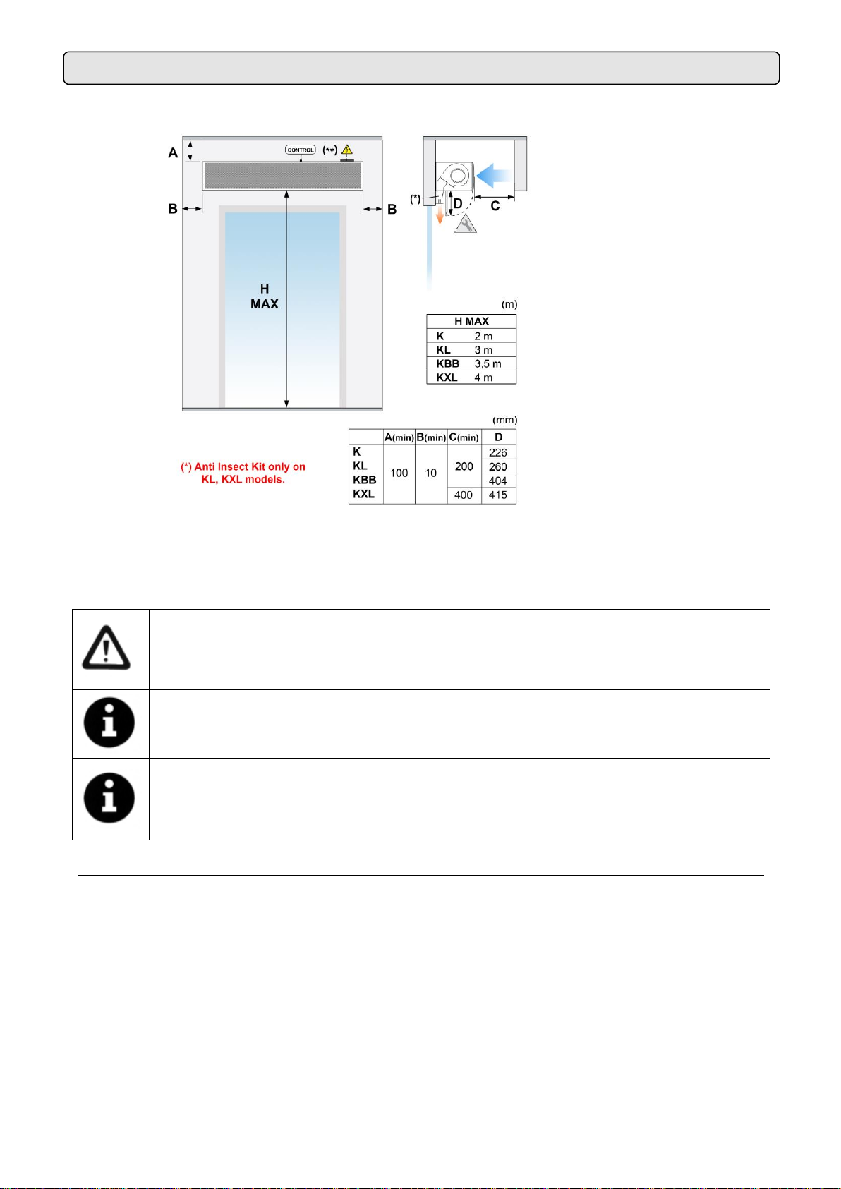
• Must be installed just above the door (not separate from it)
• With the door open, the curtain must be at maximum speed
• The curtain should be on as soon as possible when opening the door:
o By default, the “Hand Auto”control and a door contact supplied allow to automatically have
a low speed with the door closed and the maximum speed when the door is open (in this way
it reaches the maximum flow earlier).
o As an option, there is an advanced “Clever”control that has a delayed door contact that will
not let us open the door until the curtain is on.
o As an option, the door contact supplied can be changed by a motion detector in such a way
that when we perceive the approach of a person we already activate the air curtain and in
this way the curtain reaches maximum speed before opening the door.
o In low consumption EC fans that have a slower start it is more important to always have a
low speed with the door closed, or to install a detector so that they start in advance.
• In the case of indoor odours that encourage the entry of insects, the curtain should be installed
outside to work with clean air. If it is placed outside, it must be protected from the rain with a roof that
prevents the curtain from getting wet.
Power Supply
To connect the power supply there is a black connection box outside the air curtain (located on top).
For curtains, only 230V single-phase current should be connected for the fans or 400Vx3 as an option for the
Fly KL and Fly KXL models.
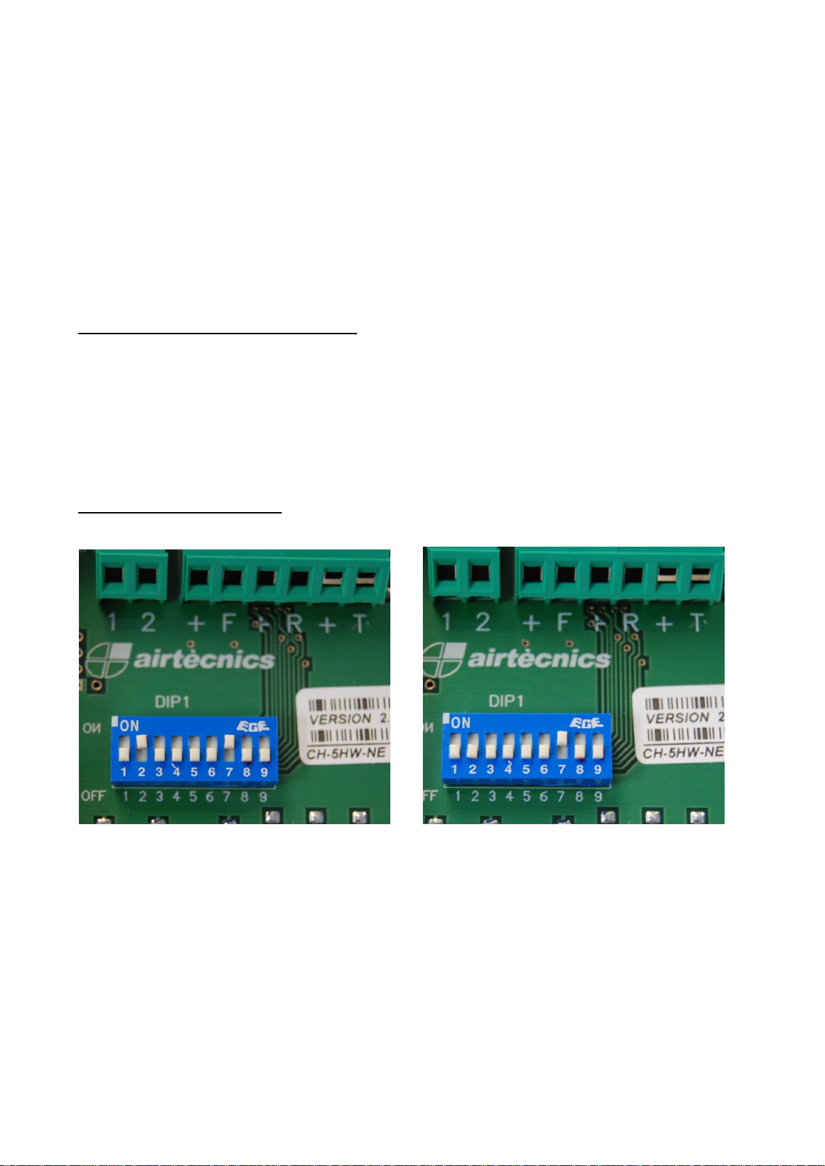
PCBoard and Control
To connect the controller there is a PCBoard (printed circuit) located outside the air curtain (located on top).
There is no need to open the unit to connect it.
Use the 7 (or 10) meters RJ45 cable supplied with the equipment. The communication between the controller
and the PCB is digital and low-voltage.
Optionally, there are different accessories and controllers available, to meet every customer needs (Clever,
door contacts, supports, etc.).
The new total control for ventilation technology is advanced Clever regulation. Leading the new generation of
air curtains management with maximum control providing maximum energy saving. For more information ask
for Clever Control manual.
Fixing
Units are provided of several external suspension points, depending on the weight and length of each model
(see exact situation of the points at the air curtains characteristics page).
Generally, air curtains are installed horizontally, for vertical installation use the foot kit (see accessories
section).
The fixing of the air curtain should be managed according to the weights of each unit shown on the technical
data page. The installation can be made through threaded rods, cable tensors or other supports. See
available supports in the accessories section.
Attention! Heavy load.
Do not step underneath hanging load during the transport or assembly.
Store in a dry place and weather protected in its original packaging. In case the packing is opened, cover the
air curtain to protect it from dust. Do not step or put heavy load over the package to avoid damages to the
material. Store temperatures are between -20ºC and +40ºC.
When carrying material, make sure it is not damaged by the forklift (fork penetration in the packaging).
Please see the Packaging indications.

7
WORKING INSTRUCTIONS
For safety, the air curtains never have to be stopped by disconnecting them from the
main supply, always through the controller and wait for 10 minutes at least to disconnect
the main supply. In case to not follow these instructions, the internal parts of the air
curtain can be damaged.
Control PCBoard characteristics
The speed of the fans is regulated by varying the input voltage of the fan assembly. The electronic board has
5 voltage outputs: 120, 140, 170, 200 and 230 Volts.
Controller’s common characteristics
•Controllers: There are several models depending on the customer’s needs
(timers, etc.).
•5 ventilation speed.
•Memory: When a power shortage happens, it guarantees that the selected speed
will be maintained when the service is re-established. This function can be
connected or disconnected through the switch ON/OFF placed inside the
controller.
•RJ45 cable and digital communication: “Plug and Play” easy and fast
connection through RJ45 cable and digital communication between the controller and the air curtain.
This kind of communication is more reliable even at long distances.
•External ON/OFF: Inside the controller we can connect a normally open contact (1, 2) that controls
the ON/OFF of the equipment through any external device, the contact is potential-free. When the
contact is Open, the air curtain is ON. When the contact is closed the air curtain is OFF. It can be
used with programmable timer, fire alarms, PLC, etc.
Common characteristics to all controllers for air curtains
The CH-5HW-NE (HAND AUTO) controller is specially designed for anti-insect curtains. In relation to the
standard regulator that we serve by default with the blind, the HAND AUTO has some additional functions.
This controller is designed for places with a door where you want to optimize the operation of the air curtain
according to the state of the door (open or closed). By automating the operation according to these variables,
better performance is achieved with lower consumption and therefore a great improvement in efficiency.
Allows manual or automatic control. Furthermore, it incorporates the functions of external On/Off, door
contact.
•Manual: manual selection of the fan speed (indicated by a green LED).
•Automatic: Works automatically depending on:
oDoor contact: The operation of this regulator is not justified without connecting it to a door
contact, so it is essential that it interact with one. It can be supplied by the manufacturer or
an existing one on the door.

8
Functioning:
▪While the door is open, we can modify the “air speed with door open”(orange led).
The curtain will operate at the chosen speed while the door is open and also during
the delay time.
▪With the door closed, we can choose the “closed door air speed”using the speed
button. The curtain will operate at this speed as long as the door is closed after the
delay time has elapsed (time from when the door closes until it returns to door
closed operation 10-150 seconds). The speed is indicated by a green led.
▪With the internal switches we can modify the delay time (time from when the door
closes until it returns to the closed door operation 10-150 seconds).
If at any time the door opens the curtain goes at door open speed.
When the door is closed, the curtain remains at the door open speed for the time stipulated
in switches 5 and 6 (delay time between 10-150 seconds).
Auxiliary functions of the CH (Hand-Auto):
•Door contact (+, T): only in automatic operation, when the door is opened, the air curtain changes
from the closed door speed (green led) to the open door speed (orange led). All types of detectors
can be used (motion sensors, infrared, etc.).
•(+, F): not used
•(+, R): not used.
•External ON/OFF (1, 2): If we close this contact, the curtain stops working, it is usually connected to
a timer, a PLC/BMS, etc.
Programming dip (CH control):
Programming for Magnetic/Mechanical door contact
2 and 7 position ON –With
magnetical/mechanical door contact
7 position ON –Without magnetical/mechanical
door contact
Inside the control box there is a small battery of microswitches numbered from 1 to 9 that serve to:
•1: OFF
•2: door contact inverter. OFF-NO position, ON-NC position.
•3: OFF

9
WIRING DIAGRAMS
•5 and 6: the combination of these two switches is used to modify the delay time from when the door
is closed until the equipment returns to normal operation.
Switch 5
Switch 6
Delay Time
Off
Off
10 sec.
On
Off
50 sec.
Off
On
100 sec.
On
On
150 sec.
•7: allows you to choose between memory ON/OFF (if the light supply is interrupted and it is ON, the
curtain will return to the previous position when the power is restored).
•8 y 9: not used
Special controls
If there is a need to be able to control more parameters, there is 1 controller that allows many more
possibilities compared to the standard control, the Clever.
The following diagrams are enclosed:
•Air curtain with Hand Auto. Fly K/Fly KBB 1000-1500-2000. Diagram: AIRDOE09041
•Air curtain with Hand Auto. Fly KBB 2500-3000. Diagram: AIRDOE09042
•Air curtain with Hand Auto. Fly KL 1000-1500/Fly KXL 1000. Diagram: AIRDOE09251
•Air curtain with Hand Auto. Fly KL 2000-2500-3000/Fly KXL 1500-2000. Diagram:
AIRDOE09867
•Air curtain with Hand Auto. Fly KXL 2500-3000. Diagram: AIRDOE09880
In case you need to connect the equipment to a PLC, the corresponding wiring diagrams will be supplied.

10

11

12

13

14

15
DATASHEET

16

17

18

19
MAINTENANCE INSTRUCTIONS
For safety, before any cleaning, disconnect power supply using the
controller.
It is forbidden to open the service door (risk of electrical discharge and
being trapped in fans).
Service and maintenance should be done only by introduced and
qualified workers.
Do not use water or steam for cleaning the internal parts and
components of the air curtain.
External cleaning
Air curtains don’t need any kind of maintenance except from the cleaning of the casing and the inlet grille.
It is recommended to weekly clean the inlet grille. It is important to make sure that the air curtain is OFF,
otherwise the dust mixed with a wet cloth would create a kind of paste that will damage the fan rotor when it
sucks the air.
Annual cleaning of the discharge area (outlet).
The casing of the air curtain should be cleaned with a wet cloth and non-aggressive detergent. Do not use
caustic soap or acids.
The inlet grille prevents the settling of dust and strange objects in the internal elements. It is recommended to
check periodically that the inlet grille is free of any object that could interfere the air entrance (plastic bags,
papers, etc.).
REPAIRS AND REPLACEMENTS
Installation and electrical connections must be done by qualified workers and following
these instructions.
Before any repairs are undertaken, please:
•Inform people that there is work in progress.
•Disconnect the power supply and protect the thermal magnet (so nobody can
restart it accidentally).
•Make sure there is no tension in the air curtain.
•Make sure the fans are stopped.
•Use only original spare parts.

20
To open the service door, follow these steps
1.- Insert a flat screwdriver between the frame and the rack and push the rack out. The grille is snap closed
with pivots. It has a safety cable to prevent accidental falls.
2.- OPTIONAL: Remove the security screw from the service door.
3.- Insert a screwdriver and press next to the pivots to open the service door. In the case of a curtain with
plenum box or suction and discharge kits, the lever must be made on the side of the door where a slot
has been made to facilitate the entry of a flat screwdriver.
Fan replacing
Before changing the fan, notify and indicate that is working, disconnect the power supply, make sure that
there is no voltage and that the fans have stopped.
K, KBB: Unplug the fan from the cable tree. Remove the fan by loosening the fixing screws and
assemble the new fan following the process in reverse order.
This manual suits for next models
19
Table of contents
Other Airtecnics Heater manuals
Popular Heater manuals by other brands

EXHeat
EXHeat HEF 30 Installation, operation, & maintenance instruction

THE RADIATOR COMPANY
THE RADIATOR COMPANY Ovali Bath Fitting instructions

Generac Power Systems
Generac Power Systems MAC 750F owner's manual

Desa
Desa 30-80 owner's manual

Stelpro
Stelpro SCR series user guide

Honeywell
Honeywell HZ425E operating instructions

Lumme
Lumme LU-FH713B user manual

HEATSTRIP
HEATSTRIP Elegance THE1800EU Operation, installation, and maintenance manual

TESY
TESY GH 200 Usage and Storage Instructions

Jaga
Jaga BRIZA 041 Wall Mounting instructions

Harvia
Harvia M45 Instructions for installation and use

USSC
USSC Ashley EC95 Installation, operation and maintenance instructions