.1'11:~'j~//:f-
...~8!iT:TiI:.
EXP Steering EXP Throttle
~~~~
-
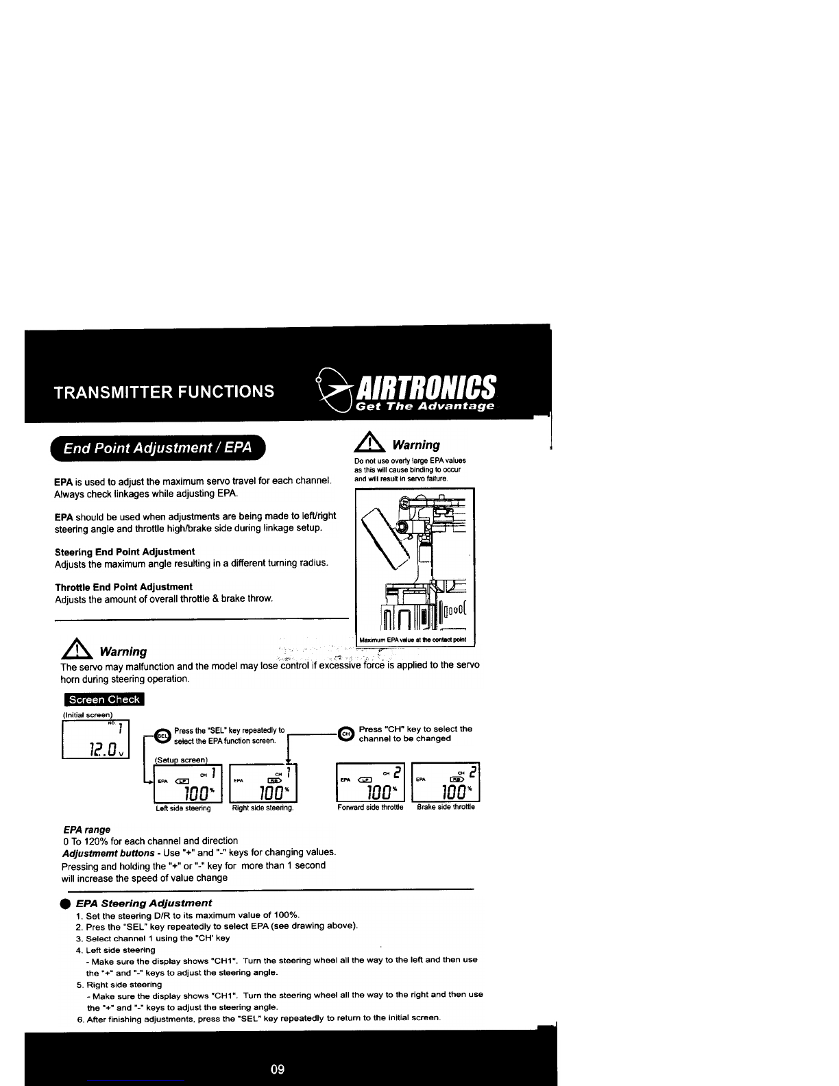
(Initial screen)
I ~ 1 I ~ Press the "SEL" key repeetedlyto
I 12.0v I ~~select theEXPIu QctiOnscreen.Datu screan~1 ~~
EXP EXP
0" 0"
EXP Range
(-)100% To (+)100% for each channel.
Adjustment buttons -use "+" or "." keys for changing values.
IP..1tIv8 S'""na EXPFa.tar S8M) movement
In centar, slower altar
EXP percentaga
~
II~
l~
Jlo~
JI~
I1OO-o--- ~
NogotIvo-EXP PooIIIw Th- EXP
Slowerservomovement Fasterservomovement
inoenter.fasraranar ;ncantar.--
EXPpetoantage EXP-
R 100 B 100
F. ~-:~ f~
I ~I ( ~I 0J
F1OO~ -F1OO-.-
Trtgger rnovemenl Trtgger -
.EPA Throttle Adjustment
1. Set the throttle D/R (DT4) to its maximum value (100%).
2. Press the "SEL" key repeatedly to select EPA.
3 Select channel 2 using the .CH" key.
4. Forward throttle adjustment
-Make sure the display shows .CH2.. Pull the throttle trigger all the way back and then use the .+. and .-.
keys to adjust maximum forward throttle amount. If using an Electronic Speed Controller. set value to 100%.
5. Brake/reverse Throttle Adjustment
-Make sure the display shows .CH2". Push the throttle trigger all the way forward and then use the .+" and
.-.keys to adjust maximum brake amount. If using an ESC (Electronic Speed Controller), set value to 100%.
6. After finishing adjustments, press the .SEL. key repeatedly to return to the initial screen.
.EXP (exponential) adjustment
EXP is used to adjust the sensitivity of control response near center for each channel (Ch 1 or Ch 2),
e Press "CH" key to select the
CH channel to be changed
EXP Steering Adjustment
1 Press the "SEL" key to select the EXP function (see drewing below).
2 Select channel 1 using the "CH" key
3 Use the "+" and "-" keys to adjust the EXP value
4. After finishing adjustments. press the "SEL" key repeatedly to return to the initial screen
* Steering EXP will work in both left and right directions.
EXP Throttle AdJustment
1. Press the "SEL" key repeatedly to select the EXP function (see drawing below).
2. Select channel 2 using the "CH" key
3 Use the "+" and "-" keys to adjust the ~XP value
4 After finishing adjustments, press the "SEL" key repeatedly to return to the initial screen
* Throttle EXP only works in forward direction
N~ S-ng EXP
ISlower servo movement
in center faster otIer
EXPpercentage
B 100
-, .
1.100~~ )