Airzone FLEXA 3.0 IBPRO6 User manual

rebmuNegaPdraobpilC
Installation Manual
FLEXA 3.0
IBPRO6


3
INDEX
Warnings and environmental policy....................................................................................................................................................................................6
Precautions...............................................................................................................................................................................................................................6
Environmental policy ...........................................................................................................................................................................................................6
System elements..........................................................................................................................................................................................................................7
Airzone Main control board (AZCE6FLEXA3 / AZCE6IBPRO6)..............................................................................................................................7
Airzone Expansion module of 2 zones (7 and 8) (AZCE6EXP8Z)........................................................................................................................7
Airzone On/off zone module (AZCE6ONOFF6Z) .......................................................................................................................................................7
Airzone Control module of radiant elements (AZCE6OUTPUT8)........................................................................................................................7
Airzone Blueface color thermostat (AZCE6BLUEFACEC) ........................................................................................................................................8
Airzone Think monochrome thermostat Wired/wireless (AZCE6THINK [C/R])..............................................................................................8
Airzone Lite thermostat Wired/Wireless (AZCE6LITE [C/R]) ..................................................................................................................................8
Airzone controller 3.0 gateway (AZX6GTC xxx) .........................................................................................................................................................9
Airzone Communication gateway (AZX6QADAPT xxx)..........................................................................................................................................9
Airzone 0-10 V Fancoil control gateway (AZX6010VOLTSZ).................................................................................................................................9
Airzone control gateway – 3 speeds fancoil (AZX6FANCOILZ).........................................................................................................................10
Airzone control gateway for electromechanical units (AZX6ELECTROMEC)...............................................................................................10
Airzone cloud Webserver Ethernet/Wi-Fi (AZX6WEBSCLOUD [C/R]) .............................................................................................................10
Webserver Airzone Cloud DIN Ethernet/Wi-Fi (AZX6WSCLOUDDIN [C/R]) .................................................................................................11
Airzone Supermaster controller (AZX6CSMASTER [S/E] [B/G]) .........................................................................................................................11
Airone Production control board (AZX6CCP) ..........................................................................................................................................................12
Airzone Aerothermal gateway (AZX6ACUACP xxx) ..............................................................................................................................................12
KNX integration gateway (AZXKNXGTWAY) ............................................................................................................................................................12
Airzone-BACnet integration gateway (AZX6BACNET) .........................................................................................................................................13
Airzone-Lutron integration gateway (AZX6GTILUT).............................................................................................................................................13
Airzone consumption meter (AZX6ACCCON) .........................................................................................................................................................13
Airzone temperature metallic probe in sheath (AZX6SONDPROTEC) ...........................................................................................................13
General requirements.............................................................................................................................................................................................................14
Introduction................................................................................................................................................................................................................................15
System installation...................................................................................................................................................................................................................15
Assembly and connection.....................................................................................................................................................................................................16
Main control board (AZCE6FLEXA3 / AZCE6IBPRO6)............................................................................................................................................16
Assembly..........................................................................................................................................................................................................................16
Connection......................................................................................................................................................................................................................16
Airzone Expansion module of 2 zones (7 and 8) (AZCE6EXP8Z) ......................................................................................................................20
Connection......................................................................................................................................................................................................................20
Airzone Control module of radiant elements (AZCE6OUTPUT8).....................................................................................................................21
Assembly..........................................................................................................................................................................................................................21
Connection......................................................................................................................................................................................................................21
Wired Airzone thermostats (AZCE6BLUEFACEC / AZCE6THINKC / AZCE6LITEC).......................................................................................22
Assembly..........................................................................................................................................................................................................................22
Connection......................................................................................................................................................................................................................22
Wireless Airzone thermostats (AZCE6THINKR / AZCE6LITER) ...........................................................................................................................23
Assembly..........................................................................................................................................................................................................................23
Changing batteries.......................................................................................................................................................................................................23

4
0-10 V Fancoil Control gateway (AZX6010VOLTSZ)..............................................................................................................................................24
Assembly..........................................................................................................................................................................................................................24
Connection......................................................................................................................................................................................................................24
Airzone control gateway-3 speeds fancoil (AZX6FANCOILZ)............................................................................................................................25
Assembly..........................................................................................................................................................................................................................26
Connection......................................................................................................................................................................................................................26
Control gateway for electromechanical units (AZX6ELECTROMEC)...............................................................................................................27
Assembly..........................................................................................................................................................................................................................27
Connection......................................................................................................................................................................................................................27
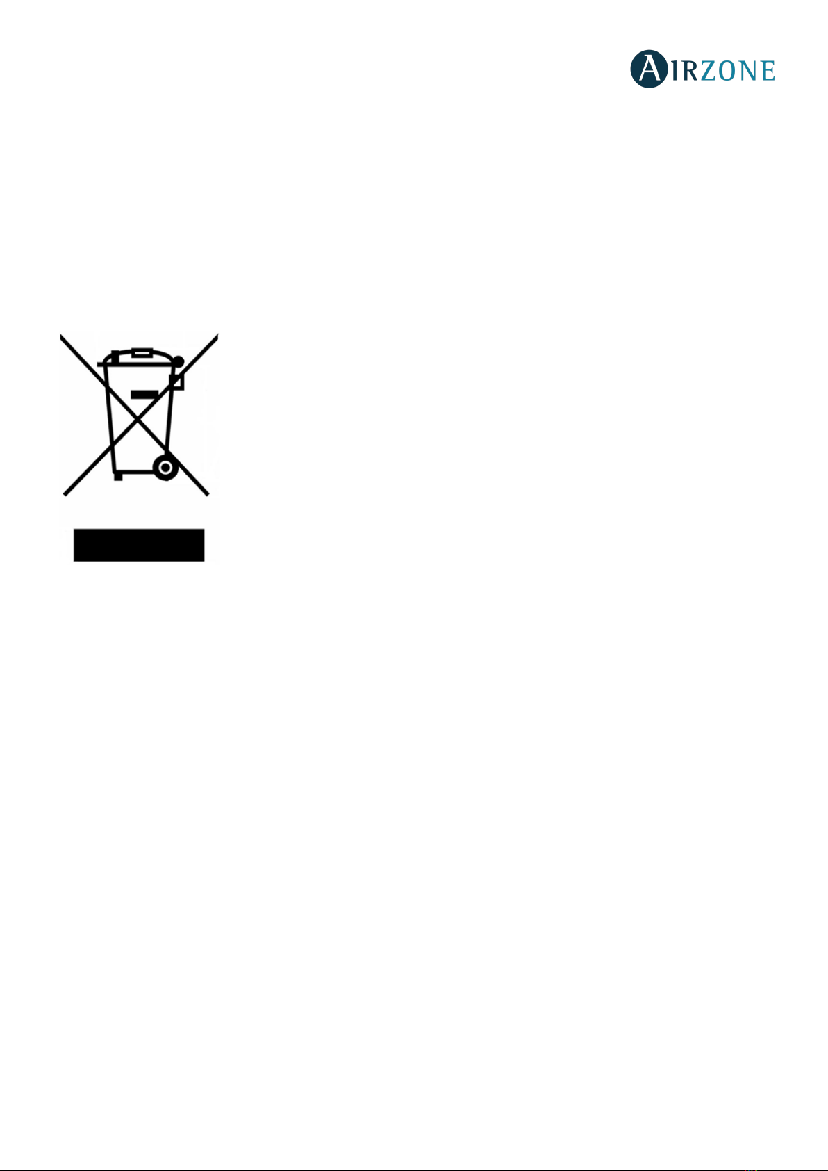
Webserver Airzone cloud Ethernet/Wi-Fi (AZX6WEBSCLOUD [C/R]) .............................................................................................................29
Assembly..........................................................................................................................................................................................................................29
Connection......................................................................................................................................................................................................................29
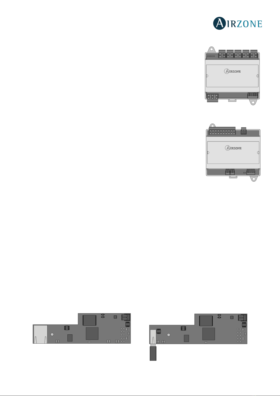
Webserver Airzone cloud DIN Ethernet/Wi-Fi (AZX6WSCLOUDDIN [C/R]) ..................................................................................................31
Assembly..........................................................................................................................................................................................................................31
Connection......................................................................................................................................................................................................................31
Airzone Supermaster controller (AZX6CSMASTER [S/E] [B/G]) .........................................................................................................................33
Assembly..........................................................................................................................................................................................................................33
Connection......................................................................................................................................................................................................................33
Airzone Production control board (AZX6CCP) ........................................................................................................................................................34
Assembly..........................................................................................................................................................................................................................34
Connection......................................................................................................................................................................................................................34
KNX integration gateway (AZXKNXGTWAY) ............................................................................................................................................................37
Assembly..........................................................................................................................................................................................................................37
Connection......................................................................................................................................................................................................................38
Airzone-BACnet integration gateway (AZX6BACNET) ........................................................................................................................................38
Configuration .................................................................................................................................................................................................................39
Airzone-Lutron integration gateway (AZX6GTILUT)............................................................................................................................................39
Assembly..........................................................................................................................................................................................................................39
Configuration .................................................................................................................................................................................................................39
Airzone consumption meter (AZX6ACCCON) .........................................................................................................................................................40
Assembly..........................................................................................................................................................................................................................40
Connection......................................................................................................................................................................................................................40
Reset...................................................................................................................................................................................................................................41
Assembly and connection evaluation..............................................................................................................................................................................41
System start-up .........................................................................................................................................................................................................................41
Airzone Blueface and Airzone Think setup...............................................................................................................................................................41
Airzone Lite setup...............................................................................................................................................................................................................44
Lite thermostat reset ...................................................................................................................................................................................................44
Initial Configuration evaluation..........................................................................................................................................................................................44
User and zone settings ...........................................................................................................................................................................................................45
User settings - Blueface thermostat ............................................................................................................................................................................45
Zone Configuration menu – airzone Blueface Thermostat................................................................................................................................45
User settings – airzone Think thermostat..................................................................................................................................................................46
Advanced settings....................................................................................................................................................................................................................47
System settings....................................................................................................................................................................................................................48

5
Zone Parameters.................................................................................................................................................................................................................49
Self-diagnose..............................................................................................................................................................................................................................50
Airzone Main control board (AZCE6FLEXA3 / AZCE6IBPRO6)...........................................................................................................................50
Airzone Expansion module of 2 zones (7 and 8) (AZCE6EXP8Z).....................................................................................................................51
Airzone Control module of radiant elements (AZCE6OUTPUT8).....................................................................................................................51
Airzone Blueface and Think thermostats (AZCE6BLUEFACEC / AZCE6THINK [C/R]) ................................................................................52
Blueface Thermostat Warnings ...............................................................................................................................................................................52
Think Thermostat Warnings .....................................................................................................................................................................................52
Blueface and Think Thermostats errors ...............................................................................................................................................................52
Airzone Lite thermostat (AZCE6LITE [C/R])...............................................................................................................................................................60
Airzone controller 3.0 gateway (AZX6GTCxxx) .......................................................................................................................................................62
Airzone Communication gateways (AZX6QADAPT xxx).....................................................................................................................................62
0-10 V Fancoil communication gateway (AZX6010VOLTSZ).............................................................................................................................63
Fancoil Communication gateway (AZX6FANCOILZ).............................................................................................................................................63
Airzone control gateway for electromechanical units (AZX6ELECTROMEC)...............................................................................................64
Webserver Airzone Cloud (AZX6WEBSCLOUD [C/R]) ...........................................................................................................................................64
Airzone Production control board (AZX6CCP) ........................................................................................................................................................65
Airzone Aerothermal gateways (AZX6ACUACP xxx).............................................................................................................................................66
Airzone-KNX integration gateway (AZX6KNXGTWAY) ........................................................................................................................................67
Airzone-BACnet integration gateway and Airzone-LUTRON integration gateway (AZX6BACNET and AZX6GTILUT)...............67
Airzone consumption meter (AZX6ACCCON) .........................................................................................................................................................68
Navigation trees........................................................................................................................................................................................................................69
Navigation Tree - Blueface Thermostat......................................................................................................................................................................69
Navigation Tree - Think Thermostat............................................................................................................................................................................70

6
WARNINGS AND ENVIRONMENTAL POLICY
PRECAUTIONS
For your security, and to protect the devices, follow these instructions:
•Do not handle the system with wet or damp hands.
•Disconnect the power supply before making any connections.
•Take care not to cause a short circuit in any of the system connections.
ENVIRONMENTAL POLICY
Do not dispose of this equipment in the household waste. Electrical and electronic
equipment contain substances that may damage the environment if they are not handled
appropriately. The symbol of a crossed-out waste bin indicates that electrical equipment
should be collected separately from other urban waste. For correct environmental
management, it must be taken to the collection centers provided for this purpose, at the end
of its useful life.
The equipment's components may be recycled. Act in accordance with current regulations
on environmental protection.
If you replace it with other equipment, you must return it to the distributor or take it to a
specialized collection center.
Those breaking the law or by-laws will be subject to such purposes and measures as are laid
down in environmental protection legislation.

7
SYSTEM ELEMENTS
AIRZONE MAIN CONTROL BOARD (AZCE6FLEXA3 / AZCE6IBPRO6)
Electronic board that controls the system through wired and wireless devices. Wall mounted.
Functionalities:
•Control and management of the thermostats (up to 6 zones or 8 zones with
expansion module).
•Power outlets for motorized elements.
•Zone On/Off module (up to 6 zones or 8 zones with expansion module) (Only
available for AZCE6IBPRO6).
•Relay outlet configurable as CMV (controlled mechanical ventilation) or
boiler.
•Gateway control management.
•Communications with units of integral control of the installation.
•Communications with other external control systems through integration bus.
AIRZONE EXPANSION MODULE OF 2 ZONES (7 AND 8) (AZCE6EXP8Z)
Expansion module for controlling zone 7 and 8 in Airzone installations. Connection and power supply through Airzone
connection bus of the main control board.
Functionalities:
•Two actuators for controlling zones 7 and 8.
•Two window contacts for controlling zones 7 and 8.
AIRZONE ON/OFF ZONE MODULE (AZCE6ONOFF6Z)
Module that allows suspending zone demand through dry voltage free contacts. Powered by
main control board. Assembled on main control board through connectors.
Functionalities:
•On/Off of the zone through voltage free contact (for example: window contact).
AIRZONE CONTROL MODULE OF RADIANT ELEMENTS (AZCE6OUTPUT8)
Control module of radiant elements for zoned heating. Communications
through system Airzone connection bus. Externally powered at 110/230 Vac.
DIN rail mounted.
Functionalities:
•Control of up to 8 radiant elements through 10 to relays at 110/230
Vac.

8
AIRZONE BLUEFACE COLOR THERMOSTAT (AZCE6BLUEFACEC)
Color graphic interface with capacitive screen for controlling zones in Airzone systems. Powered by main control board.
Finished in steel and glass. Available in white and black.
Functionalities:
•Available in Spanish, English, French, Italian, German and Portuguese.
•Control of temperature, operating mode (Master thermostat) and system speed
(Master thermostat and fancoil installations).
•Room temperature and relative humidity measurement of the zone.
•Configuration stages control (air, radiant or combined).
•Eco-Adapt function.
•Sleep function.
•Temperature and mode time schedules.
•Remote access to other zones of the system.
•Weather forecast and AC unit consumption (optional).
AIRZONE THINK MONOCHROME THERMOSTAT WIRED/WIRELESS (AZCE6THINK [C/R])
Graphic interface with low-energy e-ink screen and capacitive buttons for controlling zones in Airzone systems. Finished in
steel and glass. Wired/wireless communications. Powered from main control board (wired) or by CR2450 button battery
(wireless). Available in white and black.
Functionalities:
•Available in Spanish, English, French, Italian, German and Portuguese.
•Control of temperature, operating mode (Master thermostat) and system speed
(Master thermostat and fan coil installations).
•Room temperature and relative humidity reading.
•Sleep function.
•Remote access to other zones of the system.
•Weather forecast (optional).
AIRZONE LITE THERMOSTAT WIRED/WIRELESS (AZCE6LITE [C/R])
Thermostat with capacitive buttons for controlling the temperature of the zones in Airzone
systems. Finished in steel and glass. Wired/wireless communications. Powered from main
control board (wired) or by CR2450 button battery (wireless). Available in white and black.
Functionalities:
•On/off of the zone.
•Set-point temperature control (Accuracy: ± 1°C, max: ±3°C.)
•Room temperature and relative humidity reading.

9
AIRZONE CONTROLLER 3.0 GATEWAY (AZX6GTC XXX)
Gateway for the management of AC units compatible with Airzone control systems. Powered
by the indoor unit. Assembly and connection on the AC unit bus of the enabled Airzone
devices. Product developed and tested in collaboration with the manufacturer.
Features:
•Two-way communication of the basic control parameters depending on the demand of the
Airzone control system.
•Automatic control of speeds, enabling (generally) the operating without bypass.
•Adjustment of the set point temperature based on the selected temperatures in the
Airzone thermostats and the Eco-Adapt algorithm.
•Reading of the operating temperature of the system.
•Reading of warnings and errors of the controlled unit.
•Master control of the unit.
AIRZONE COMMUNICATION GATEWAY (AZX6QADAPT XXX)
Element that fully integrates AC units and Airzone zoning systems, enhancing the
performance of the installation:
•ON/OFF depending on the number of zones where there's demand.
•Automatic mode changeover (Stop, Ventilation, Cooling, Heating or Dry) from
master thermostat.
•Automatic fan speed selection based on the number of zones on demand.
•Set-point temperature adjustment based on the set-point temperatures of the zone thermostats of the system and
Eco Adapt algorithm.
AIRZONE 0-10 V FANCOIL CONTROL GATEWAY (AZX6010VOLTSZ)
Control gateway of air-to-water zoning units. Fan control through 0-10 V output and opening-
closing electrovalves Compatible with 2-pipe and 4-pipe installations. Externally powered at
110/230 Vac. Mounted on DIN rail or on wall.
Functionalities:
•Two relays for electrovalve control by demand.
•0-10 V output for fan control.
•Automatic speed control based on the demand of the zones.

10
AIRZONE CONTROL GATEWAY – 3 SPEEDS FANCOIL (AZX6FANCOILZ)
Control gateway for air-to-water air conditioners. Control up to three fan-speeds and
opening/closing of electro-valves. Compatible with 2 or 4-pipe air conditioners. Externally
powered. Mounted on DIN rail or on wall.
Functionalities:
•Two electro-valve control relays for demand.
•Three control relays for fan-speed selection.
•Automatic fan speed selection based on the number of zones where there is demand.
AIRZONE CONTROL GATEWAY FOR ELECTROMECHANICAL UNITS (AZX6ELECTROMEC)
Control gateway for air-conditioning units with electromechanical control. Management of
up to two compressors in 1 stage (balanced) or 2 stages. Powered through AC unit bus.
Mounted on DIN rail or on wall.
Functionalities:
•Relay for fan control.
•Relay to control up to two compressors.
•Relays to control heating/cooling modes.
•Relay for boiler control.
•Two Airzone probe inputs for protection of production units.
AIRZONE CLOUD WEBSERVER ETHERNET/WI-FI (AZX6WEBSCLOUD [C/R])
Webserver for controlling systems through Airzone Cloud platform. Accessible through browser or app (available for IOS and
Android). Connection via router (AZX6WEBSCLOUDC) or Wi-Fi (AZX6WEBSCLOUDR). Powered through domotic bus.
Functionalities:
•Control of up to 32 systems.
•Configuration and control of zone parameters (Room and set-point temperature, operating mode, etc.) and system
settings via Airzone Cloud.
•Temperature and operating mode time schedules.
•Multi-user and multi-session.
•External control through Airzone Cloud platform.
•Remote updates of the Webserver firmware and the systems connected to it.
•Remote error detection and error resolution.
AZX6WEBSCLOUDC
AZX6WEBSCLOUDR

11
WEBSERVER AIRZONE CLOUD DIN ETHERNET/WI-FI (AZX6WSCLOUDDIN [C/R])
Webserver for controlling Airzone systems through Airzone Cloud platform. Accessible through browser or App (available for
IOS and Android). Connected to router via Ethernet (AZX6WSCLOUDDINC) or WiFi (AZX6WSCLOUDDINR). Externally power
supplied at 110 / 230 Vac. Mounted on DIN rail or on wall.
Functionalities:
•Control of up to 32 systems.
•Configuration and control of zone parameters (Room and set-point temp., operating mode, etc.) and system
parameters via Airzone Cloud.
•Temperature and Operation mode time schedules.
•Multi-user and multi-session.
•External control through Airzone Cloud platform.
•Remote updates of the Webserver firmware and the systems connected to it.
•Remote error detection and error resolution.
AIRZONE SUPERMASTER CONTROLLER (AZX6CSMASTER [S/E] [B/G])
Monochrome LCD touch screen back-lighted controller for managing the system of the installation. Powered through AC unit
bus. Wall-mounted (AZX6CSMASTERS) or wall-embedded (AZX6CSMASTERE). Available in white and grey.
Functionalities:
•Up to 8 control groups.
•Operating mode and set-point temperature control.
•Forced mode control: it imposes the operating mode and the temperature, blocking the user control.
•Semi-forced mode control: it imposes the mode range and the temperature every hour.
•Forced mode control: it imposes the operating mode and the temperature, blocking the control for the user.
•Temperature time schedule for the installation.
•Operating mode time schedules.
AZX6CSMASTERE AZX6CSMASTERS
Important: This device is not compatible with the Production Control Board (AZX6CCP).
AZX6WEBSCLOUDDINC
AZX6WEBSCLOUDDINR

12
AIRONE PRODUCTION CONTROL BOARD (AZX6CCP)
Control board of production units through 6 relays of 10 A at 110/230 Vac. Communications through domotic bus. Externally
powered. Wall mounted.
Functionalities:
•Controls up to 32 systems.
•Controls cooling and heating mode through 2 relays.
•Controls cooling air and the heating air demand through 2 relays.
•Controls the cooling and heating radiant element demand through 2 relays.
•3 Inputs for semi-forced mode.
•Input for boiler probe.
AIRZONE AEROTHERMAL GATEWAY (AZX6ACUACP XXX)
Aerothermal-Airzone communication gateway. Powered through the AC unit bus of the production control board (AZX6CCP).
Functionalities:
•Includes energy efficiency algorithms.
•Remote start-stop function.
•Operating mode synchronization with Airzone systems (cooling and heating).
•Imposes water production temperature based on the demand.
KNX INTEGRATION GATEWAY (AZXKNXGTWAY)
Airzone integration gateway of HVAC systems into KNX TP-1 control systems through Modbus. Powered through KNX bus.
DIN-rail mounting.
Functionalities:
•One Airzone system per KNX gateway.
•Full KNX.
•KNX standard data.
•Easily configurable from ETS.
•Zone control through KNX devices.
•Type of installation control.
•Communication errors detection.

13
AIRZONE-BACNET INTEGRATION GATEWAY (AZX6BACNET)
Integration gateway for controlling Airzone installations through BACnet platform. Connected to router
via Ethernet. Power supplied through the main control board domotic bus.
Functionalities:
•One BACnet gateway per system.
•Status of window contact and presence contact of each zone.
•Status of the radiant stage of each zone.
•On/Off of each zone.
•Set-point temperature control of each zone.
•Operating mode status.
•State and Fancoil fan speed.
AIRZONE-LUTRON INTEGRATION GATEWAY (AZX6GTILUT)
Integration gateway for Lutron control systems on Airzone systems through Lutron HomeWorks QS
Processor. Connected via Ethernet. Power supplied through the main control board automation bus.
Features:
•One Airzone-Lutron interface per system.
•Reading/Writing of the room temperature.
•Reading/Writing of the set-point temperature.
•Reading/Writing of the operating mode.
•Reading/Writing of the cooling/heating demand.
•Reading/Writing of the fan speeds
AIRZONE CONSUMPTION METER (AZX6ACCCON)
Module that calculates and displays the energy consumption of single-phase HVAC units for Blueface
thermostat and Airzone Cloud. Wireless communications. Externally powered at 230 Vac. Din rail
mounted.
Functionalities:
•Calculation of energy consumption at the period of use.
•Calculation of the current energy consumption.
•Representation of daily, monthly and annual period chart at Airzone Cloud.
•Energy consumption comparison between different periods of time at Airzone Cloud.
AIRZONE TEMPERATURE METALLIC PROBE IN SHEATH (AZX6SONDPROTEC)
Temperature probe in metal sheath.
Functionalities:
•Protection probe for return water (to boiler).
•Configurable as remote or distributed probe.

14
GENERAL REQUIREMENTS
Strictly follow the directions outlined in this manual:
•This system must be installed by a qualified technician.
•Verify that the units to be controlled have been installed according to the manufacturer's requirements and operate
correctly before installing the Airzone System.
•Locate and connect all the devices of the installation in accordance with the electronic regulations in force.
•Verify that the air conditioning installation to be controlled is in accordance with the regulations in force.
•It is necessary to use a Blueface Thermostat to have all the features of the Airzone system.
•Follow these recommendations to locate the thermostats:
•Perform all the connections with total abscense of power suppliance.
•In order to connect the elements of the system, use a proper cable cable: shielded twisted pair cable formed by 4 wires:
2x0,22 mm2+ 2x0,5mm2.
•Do not place the system bus close to lines of force, fluorescent lights, LED lamps, motors, etc. It might cause
interference on the communications.
•Respect the connection polarity of each device. A wrong connection may seriously damage the product.
•For elements externally powered at 110 /230 Vac, for the communications, it is only necessary to connect the poles "A"
and "B" of the bus.
•For elements externally powered at 110/230 Vac, respect the connection polarity. A wrong grounding may produce
electric shocks.
•According to the current local and national regulations, it is mandatory to add a switch (or other element to disconnect
the system) to the external supply wiring so that a constant separation between poles is guaranteed. The system will
restart automatically if the supply is eventually turned off. Use an independent circuit from the controlled system
for the power supply.
•Once the Airzone system is configured, verify that the static pressure of the duct system complies with the air
distribution network conditions where is installed (check the Manufacturer’s Manual of the equipment if you need to
modify this parameter).

15
INTRODUCTION
Airzone systems enable the management of Master and Zone interfaces. Master thermostats enable mode management or
define the efficiency level with the Eco-Adapt function.
It is recommended the use of a Blueface thermostat as Master Interface, this enables time schedule management and more
unique functionalities.
Remember: This system only admits one Master thermostat.
To distinguish a Master Interface from a Zone Interface, check the next points:
-Blueface Master: Mode, Eco-Adapt and Speed* icons shown in white color.
-Blueface Zone: Mode, Eco-Adapt and Speed* icons shown in gray color.
-Think Master: Accessing the settings menu, Operation Mode and Speed* are available.
-Think Zone: Accessing the settings menu, Operation Mode and Speed* are unavailable.
*Note: Only available on installations with Fancoil.
SYSTEM INSTALLATION
Before the Airzone system commissioning, please check:
•The system is going to control works correctly without the Airzone system installed.
•In direct expansion unit systems, the indoor unit wired thermostat has been installed.
In order to install the system, carefully follow these steps:
Connect all the necessary elements (see section Assembly and connection)
-Connect the actuators.
-Connect the communication gateway.
-Connect all the elements of the system (thermostats, modules, etc.).
-Power the main board.
Check all the assembly and the connection are correct (see section Assembly and connection evaluation)
Configure the system
-Configure all the thermostats (see sections Initial configuration and Advanced settings).
Access all our technical documents and the self-diagnosis section, check the most FAQs,
certificates, watch our videos and read our declaration of conformity at:
myzone.airzone.es/products/

16
ASSEMBLY AND CONNECTION
MAIN CONTROL BOARD (AZCE6FLEXA3 / AZCE6IBPRO6)
Assembly
The production control board is supplied in a box to be screwed to the wall (Fig. 1). It is
should be placed and mounted in accordance with the current electrotechnical regulations.
For the mounting of the main control board, follow the following steps:
•Locate the control board close to the unit to be controlled.
•Unscrew the cover securing the back part to the wall.
•Make all the connections and screw the cover again.
In Flexa 3.0 systems, it is possible to add a remote zone ON/OFF module to the main control
board (AZCE6ONOFF6Z). To do this, insert the module in the corresponding connectors of the main board (Fig. 2).
Fig. 2
Connection
Fig. 3
Airzone connection bus connectors
The Airzone connection bus allows you to connect all the internal components dependent on the main board to control up to
6 zones (or 8 with the expansion module AZCE6EXP8Z). These are the elements that can be connected:
-Blueface (AZCE6BLUEFACEC), Think (AZCE6THINKC) and Lite (AZCE6LITEC) thermostats.
-Airzone Control module of radiant elements (AZC3POUTPUTC6).
-Expansion module (AZCE6EXP8Z).
No.
Description
Airzone connection bus
Wireless Module
SW1
Automation bus
AC unit bus
Damper outputs
Alarm input (normally closed)
Temperature probe
CMV/Boiler
AC start-stop relay
Power
On/Off module (Only AZCE6IBPRO6)
Fig. 1

17
If using a wired thermostat, connect it in one of the 3 Airzone connection bus terminals. The
connection can be both a Bus connection or a star connection. Use (2x0.5+2x0.22 mm2) Airzone
wire. For added security, secure the wires using the turrets.
Important: For elements externally powered at 110/230 Vac, for their communications, it is only
necessary to connect the poles "A" and "B" of the bus. Use the shield only on the connector of the
main control board.
In case of wireless element, check it has the battery on.
SW1
The main control board can also connect to Airzone wireless elements. These elements are associated by
opening the wireless association module of the main control board. Press on SW1 and wait for the LED 19
to remain red (Fig. 6). The wireless association module will be open during 15 minutes.
Reset system: If you want to return to factory values, press and hold on SW1 until LED D19 stops blinking.
Domotic bus connector
The domotic bus allows you to interconnect multiple systems in order to control them through Airzone control peripherals or
to integrate them into a superior control network. These are the elements that can be connected:
-Airzone Webserver Cloud (AZX6WEBSCLOUD [C/R]).
-KNX integration gateway (AZXKNXGTWAY).
-Airzone-BACnet integration gateway (AZX6BACNET).
-Airzone-Lutron integration gateway (AZX6GTILUT).
-Production control board Airzone (AZX6CCP).
-Airzone Supermaster controller (AZX6CSMASTER [S-E])
It has a 5-pin terminal for the domotic bus connection. This system can only be connected by bus.
Attach the wires with the terminal screws following the color code (Fig. 7).
Note: For elements externally powered at 110/230 Vac, for the communications, it is only necessary to
connect the poles "A", "B" and “Shield” of the communication bus. Use the shield only on the connector
of the main control board.
AC unit bus connector
The AC unit bus allows you to connect different control gateway to the AC unit. These are the gateways that can be connected:
-Airzone controller 3.0 gateway (AZX6GTC xxx).
-Airzone Communication gateway (AZX6QADAPT xxx).
-Airzone 0-10 V Fancoil Control gateway (AZX6010VOLTSZ).
-Airzone Control Gateway – 3 speeds Fancoil (AZX6FANCOILZ).
-Electromechanical communication gateway (AZX6ELECTROMEC).
Fig. 5
Fig. 6
Fig. 4
Fig. 7

18
It has a 4-pin terminal to connect the AC unit bus. The connection for these elements is point-to-
point. Attach the wires with the terminal screws following the color code (Fig. 8).
Note: For elements externally powered at 110/230 Vac, for the communications, it is only necessary to
connect the poles "A", "B" and “Shield” of the communication bus. Use the shield only on the connector of
the main control board.
To connect integrated gateways, disconnect the AC unit bus terminal and insert the connector and the fixing post of the
gateway (Fig. 9).
Fig. 9
Actuator outputs
12-V actuator outputs allow you to connect Airzone motorized elements and manage them from the main control board (up
to 8 actuators per board, up to 2 engines per output).
There are 6 two-pin terminals available to connect the motorized dampers.
Attach the wires with the terminal screws following the color code (Fig. 10).
Alarm input
This input closes all the dampers and imposes Stop mode when there is an alert. This input is configured as normally closed.
For proper operation of the system, this contact is supplied with a bonding jumper.
Temperature probe connector
It measures the outdoor temperature through an external probe. We recommend the use of this probe when using
electromechanical units or NON-Inverter units (when it is necessary to control the return temperature of the units).
CMV/Boiler connector
This output can be configured as controlled mechanical ventilation control or boiler control. (See Blueface Advanced
Configuration Menu, system parameters)
CMV configuration
Status
Stop
Ventilation
Cooling
Air heating
Heating radiant
Demand ON
CMV OFF
CMV ON
CMV ON
CMV ON
CMV ON
Demand OFF
CMV OFF
CMV ON
CMV ON
CMV ON
CMV ON
Boiler configuration
Status
Stop
Ventilation
Cooling
Air heating
Heating radiant
Demand ON
BOIL. OFF
BOIL. OFF
BOIL. OFF
BOIL. OFF
BOIL. ON
Demand OFF
BOIL. OFF
BOIL. OFF
BOIL. OFF
BOIL. OFF
BOIL. OFF
Relay specs: Imax = 1 A at 24/48 Vac, voltage-free. Note that to control elements with a greater power, it is recommended to use
contactors in accordance with the power required.
Fig. 10
Fig. 8

19
AC Start-stop relay
This output is developed to start-stop AC units. Logic of operation of the output:
Status
Stop
Ventilation
Cooling
Air heating
Heating radiant
Demand ON
AC UNIT OFF
AC UNIT ON
AC UNIT ON
AC UNIT ON
AC UNIT OFF
Demand OFF
AC UNIT OFF
AC UNIT OFF
AC UNIT OFF
AC UNIT OFF
AC UNIT OFF
Relay specs: Imax = 1 A at 24-48 Vac, voltage-free. Note that to control elements with a greater power, it is recommended to use
contactors in accordance with the power required.
Power supply connector
This connector powers the main control board and all the elements connected to it. Externally
powered at 110/110/230 Vac. It is connected through a 3-pin terminal. Attach the wires with
the terminal screws following the color code (Fig. 11).
For added security, secure the wires using the turret (Fig. 12).
Fig. 12
According to the current local and national regulations, it is mandatory to add a switch (or other element
to disconnect the system) to the external supply wiring so that a constant separation between poles is
guaranteed. The system will restart automatically if the supply is eventually turned off.
Use an
independent circuit from the controlled system for the power supply.
Remember: Once all the connections are made, make sure you replace the cover properly (Fig. 13).
Fig. 13
Fig. 11

20
On/Off module
These connectors switch on/off the zone using a voltage-free mechanical component. It is a Plug&Play module; it just has to be
connected and then recognized by the system to start operating. The logic of operation is normally closed.
For a proper operation, it is supplied with a bonding jumper.
Important: Use a shielded cable to control the inputs of the module.
Note: When you open the contact of a zone, all the elements controlled in the zone close and the thermostat indicates there is an
open input (Fig. 14).
Fig. 14
AIRZONE EXPANSION MODULE OF 2 ZONES (7 AND 8) (AZCE6EXP8Z)
Connection
The expansion module is integrated into the Airzone connection bus of the main board. It has 3 4-pin terminals, disconnect
one of the terminals and fit in the module connector (Fig. 15).
Fig. 15
There are 2 two-pin terminals available to connect the motorized dampers . Attach the
wires with the terminal screws following the color code (Fig. 16).
1 2 3 4 5 6
No.
Meaning
1
ON-OFF contact - Zone 1
2
ON-OFF contact - Zone 2
3
ON-OFF contact - Zone 3
4
ON-OFF contact - Zone 4
5
ON-OFF contact - Zone 5
6
ON-OFF contact - Zone 6
No.
Description
Microcontroller
Window contact
Actuator outputs
Airzone connection bus
Fig.16
Other manuals for FLEXA 3.0 IBPRO6
3
Table of contents
Other Airzone Accessories manuals
Popular Accessories manuals by other brands

Hyundai
Hyundai WS SENZOR 1819 user manual

STEINEL
STEINEL IS 2180-2 operating instructions

Kettler
Kettler PW25 Assembly instructions

Honeywell
Honeywell NOTIFIER FSV-951 Installation and maintenance instructions

Keating Of Chicago
Keating Of Chicago BB Service instructions

Panasonic
Panasonic MA3J7420G Specification sheet

Siemens
Siemens SIWAREX WL230 BB-S SA operating instructions

BRASS MONKEY
BRASS MONKEY GH1970 instruction manual

Sansui
Sansui ESSENTIAL Series instruction manual

LI-COR
LI-COR 1400-101 Operation and installation instructions

Pro-Ject Audio Systems
Pro-Ject Audio Systems Speed Box II Instructions for use

Ursalink
Ursalink AM100 Series Configuration guide