AK Models MIG-29 Fulcrum User manual

1
AK Models
Legendary MIG-29 Fulcrum.
A High Performance Jet-Like Model that Flies like a sport plane.
This booklet divides the construction into sub-assemblies: fuselage, wing, etc. Read each section carefully and identify all of
the parts before starting on particular sub-assembly. There is a complete description of all kit parts under “Kit Contents”.
Please check to be sure that your kit is complete; that it is not missing any parts. If you do find that parts are missing, or if you
are having trouble identifying parts please let us know. The pictures in this manual clarify and detail many of the assemblies
shown on the plan, and the two should be used together during construction.
Should you experience a problem with this kit feel free to call or write:
Thank you for choosing AK Models.
Good luck to you and have fun building and flying
MIG-29 Fulcrum.
AK Models
1635 Hemingway Lane,
Iowa City, IA 52240
(319) 358-1399
akm@ak-models.com
This product is sold with exclusion of all warranty expressed or
implied, statutory or otherwise. Buyer assumes all risk of use.

2
NOTES BEFORE BEGINNING CONSTRUCTION
Any references to right or left refers to your right or left as if you were seated in the cockpit.
To build good flying models, you need a good straight building board. Crooked models do not fly well! The
Building board can be a table, a workbench, a reject “door core” from the lumberyard, or whatever - as long as
it is perfectly flat and untwisted. Cover the top surface of the building board with a piece of celotex-type
wallboard or foam board, into which pins can be easily pushed. Do not hesitate to use plenty of pins during
assembly to hold drying parts in their correct position. When pinning and gluing parts directly over the full-size
plans, cover the plan with wax paper to prevent gluing the parts to the plans. Do not use a ballpoint pen for
making marks on the model during construction. If not sanded off, these ink marks will show through the
model’s final finish. Use pencil instead of a pen. The laser-cut balsa and plywood parts can be identified using
the plans and the “KEY TO LASER-CUT PARTS”. Mark the identification or the corresponding parts before
removing them from the laser-cut sheets.
DO NOT AD LIGHTNING HOLES TO ANY PARTS! IT WILL JEOPARDIZE STRUCTURAL
STRENGTH AND MAKE BALANCING MODEL DIFFICULT.
To build MIG-29 Fulcrum you will also need:
• Engine 2-Stroke .60 - .75
• Engine mount w. hardware (Dave Brown 60FS-6004)
• 2 1/2” Spinner (GreatPlanes GPMQ4521)
• Front Landing Gear Bracket and steering arm
• (3) - Wheels: 3” (Du-Bro 300T)
• (1) - Front Landing Gear wire (Du-Bro 154)
• (1) Axle for Front gear (Du-Bro 615)
• (6) - 5/32 wheel collars (Du-Bro 598)
• (1) - 14 oz Fuel tank (Du-Bro 414)
• (1 set) Sullivan Push-rods (Blue/Gold #506)
• (9) 2-56 - 12” Push-rods (Du-Bro 801)
• (4) 4-40 - 12” Push-rods (Du-Bro 802)
• (2) 10-24x4” bolts with blind nuts
• 2 Rolls of Covering
• 4 Channels Radio w. 6 Servos
• (2) 1/2A Control Horns (Du-Bro 107)
• 2” Nylon Reinforcing Tape (GreatPlanes LXK255)
• (2) Nylon Torque Bearings (GreatPlanes GPMQ4270)
• (4) E/Z Adjust Horn Bracket (Du-Bro 557)
• (6) L.G. Retaining Straps ( Du-Bro 158)
• Medium Fuel Tubing (Du-Bro 222)

MIG-29 FULCRUM by AK Models.
3
PREPARE TO BUILD.
• Remove all puzzle tabbed parts from their sheets. Keep all
other parts in their sheets until needed.
Fuselage sides (2)
Fuselage bottom (1)
Engine sides (inside and outside) (2) of each
Engine bottom (2)
Fuselage outside-bottom (2)
• Glue all parts together with Thick CA and ruler to keep
part’s side straight. Glue 1/16 doublers to fuselage side
making right and left sides.
• Remove F1 & F2, epoxy together.
• Remove ribs W2, W4 and their plywood doublers, epoxy
together making right and left sets.
• Mark center and thrust lines on F1, install engine mount
hardware. Install front L.G. hardware on to F2. Make
necessary openings for steering arm on the left side as if
you sit in the cockpit.
• Build vertical fins. Glue all parts together except rear part
that holds torque rod. You will do it later.
• Build stabilizer and place fiberglass cloth over the center
line (top and bottom). Glue servo trays. Round leading
edge and sides of the stabilizer.
• Slide nylon bearings on to 4/40 torque rods and make
bends as per plans (note that they are slightly different),
also cut slots in to stabilizer for nylon bearings.
• Pin stabilizer to building board (BB), with servo trays on
top.
• Use Chap Stick to lubricate torque rods where they will
be placed in epoxy. Glue nylon bearings in with epoxy.
• Cut grooves in to tailpipe base on the side that holds
torque rods. Trim stabilizer and tailpipe base for rod
clearance (see plans). Fill grooves with 15 min. epoxy and
place over the torque rods as per plan. Wipe off any extra
epoxy. Wait 15-20 min. and move rods back and forth to
brake loose from epoxy.

MIG-29 FULCRUM by AK Models.
4
FUSELAGE.
• Cover plans and pin down fuselage bottom. Draw former
lines over fuselage bottom. Place fuselage sides vertical to
BB; align sides with bottom and tack glue sides to
bottom.
• Place and tack glue F4 through F8 and then F3, F and F1.
Use former guide (F.G.) by placing it behind all formers
while applying glue.
• Go back and permanently glue all formers and sides
together using thin CA on formers and Med. CA on fuse
sides and bottom.
• Measure and cut 1/2 triangle to be placed behind F1 and
F2. Epoxy triangles in.
• Make a top fuselage sheeting for F1-F2, F3-F4 and F6-F8.
Measure and cut from hard 1/8x2x36 balsa. Glue top
sheeting in. Sand top & sides for 3/16 corners.
• Measure, cut from 3/16x2x48 and glue top corners to F1-
F2, F3-F4 and F6-F8. Sand flush with top and sides.
• Remove fuse from BB and flip over. Sand sides and
bottom for 3/16 bottom corners. Cut 1” triangle to fit next
to fuselage corner and half way on to F3. Glue in place.
• Glue 3/16 bottom corners. Round well all 3/16 corners as
per plans, do not trim triangle at this time.

MIG-29 FULCRUM by AK Models.
5
• Pin fuse back to plans. Draw vertical and thrust line for
F2 and F3 on the side of the fuselage. Mark thrust line on
F2 and F3.
• Glue all formers from F2 to F8 in place.
• Mark 1/8 on bottom inside of wing saddle.
• Glue wing saddle to F4, F5 and F6 keeping it flat on BB
between F5 to F6.
• Slide Fuselage outside-bottom starting at F4. Align it at
rear of F8, wing saddle and lines on the plan. Use vertical
fins to perfectly space F6 and F8. Glue Fuselage outside-
bottom in place.
• Trim sides of F2 and F3 to except LERXes sides. Glue
LERXes sides aligning them at the top of formers; trim
1/2 triangle to fit at F4 joint.
• Cut 1/8x1/4 to make sheeting rails for F8. Glue them on
the front side of F8.

MIG-29 FULCRUM by AK Models.
6
• Glue in vertical fins, keeping them vertical to BB and
tight to formers. Glue 1/2 triangles where indicated on the
plan.
• Cut out patters from Wing plan, cut 3/32 sheeting using
them. Remove all pins from area to be sheeted. Fit and
glue rear-top sheeting in place.
• Glue in place top LERXes. Trim front and sides us
necessary.
• Slide stabilizer assembly in place; check alignment and
glue to vertical fins and F8. Also ad 1/2” triangles as
shown on the picture.
• Pin 3/8x1X36 stick (that will be used as a Leading edge
for the wing) to the top of F4, F6 and F8. Put pins so they
go in to formers. See picture.
• Unpin fuselage and flip it over placing it on the BB. It
will be seating on vertical fins and nose section.
• FUSELAGE IS NOT STRONG ENOUGH AT THIS
POINT TO HOLD TOO MUCH PRESSURE. NEXT
FEW STEPS BE CAREFUL NOT TO PUSH DOWN
TOO HARD. IF YOU NEED TO PUSH DOWN USE
HAND TO HOLD FROM UNDERNEATH OF
FUSELAGE.
• Glue all bottom parts of all formers in places using a Med.
CA.
• Trim bottom LERXes and glue in place.

MIG-29 FULCRUM by AK Models.
7
• Place inside engine side in a position. Align with formers
corners and glue first to formers and then to center section
of the fuse. Tip: “Sharpen” the edge that goes in to slots
by sanding it VERY lightly.
• Follow step above to install outside engine side.
• Glue in place bottoms of the engines.
• Epoxy wing bolt plates making sure they placed on to
former below at one end.
• It is a best time to install pushrods (throttle and steering).
Install, measure, cut outer pushrods and epoxy them only
to F7 at this time. Keep pushrods housing pointed to sides
of servo trays. See picture.
• Glue 2” long 1/2 triangles to bottom and sides of the
fuselage to support wing bolt plates. In addition, install
1/2 triangles to all joint indicated on the plans.

MIG-29 FULCRUM by AK Models.
8
• It is recommended to use some kind of Airplane stand for
next steps, as it will require plenty of sending.
• Sand engine sides and bottoms to except 3/16 corners.
Engine corners are made of two parts; front and rear. Cut
two 15” long 3/16x2 and four 10” pieces. Cut 15” long
pieces in half-length way.
• Glue rear corners in, placing them flush with F8. Install
front corners. Trim corners flush with engine bottoms and
sides. Also, sand corners at F8 and match intakes angle.
• Use 1/8 balsa to sheet intakes making sure grain goes
from side to side.
• Glue 2” long 1/2 triangles to bottom and sides of the
fuselage to support wing bolt plates. In addition, install
1/2 triangles to all joint indicated on the plans.
• It is recommended to use some kind of Airplane stand for
next steps, as it will require plenty of sending.
• Sand engine sides and bottoms to except 3/16 corners.
Engine corners are made of two parts: front and rear. Cut
two 15” long 3/16x2 and four 10” pieces. Cut 15” long
pieces in half-length way.
• Glue rear corners in, placing them flush with F8. Install
front corners. Trim corners flush with engine bottoms and
sides. Also, sand corners at F8 and match intakes angle.

MIG-29 FULCRUM by AK Models.
9
• Use 1/8 balsa to sheet intakes making sure grain goes
from side to side.
• Cut off fuse extensions flush to F8. In addition, cut off 1”
from front part of extensions. Put them aside.
• Mark Tail pipe base lines on F9s over the plans so grain
goes vertical. Glue them in place keeping 90 deg. to tail
pipe base.
• Cut four 7 1/4” long 1/8x1 balsa. Position in place and
glue to F8, stabilizer and F9. Once glued to stabilizer,
make a relief cut (not all the way through) approximately
2” long in the middle of sheeting starting from the F9 end.
It will make it easier to round it over F9. See picture.
• Cut opening (1/2” high by 1” long) for servo wires in
inboard sides only. See picture above.
• Cut four 7 1/2” long 1/8x1 balsa, trim end contacting F8
and glue to F8 first and then to F9. Make a relief cut once
again. Sand seams, fill it with Med. CA, and sand over
while it is curing.
• From 7 3/4” long 1/4x2, mark and cut as in picture above
make four parts. Trim inside of 1/8 sheeting this time.
Glue parts made above to F8 and F9, sand seams and fill
with Med. CA. Also, run Med. CA on the inside through
servo tray opening.
• Sand structure smooth and round. Place 1/4 Balsa Hatch
centered over the tail cone and mark it’s position with
pen. Cut out hatch opening keeping it as close as possible
for good fit.

MIG-29 FULCRUM by AK Models.
10
• Glue 2” long 1/4x3/8 hatch rail to F8 (let hatch stick out a
little); also trim F9 so hatch can be lowered to match sides
(see picture above). Install hatches and drill holes for
mounting screws (two in front and one at rear). Screw
hatches down and sand to make a good transition.
• Take previously cut off fuse extensions and place them
next to tail cone wire opening, try-fit 1/8 rear sheeting.
Trim as needed and glue in place, extensions and
sheeting.
• Use building pin to mark through openings for rudder
torque-rods. Make 1/4 opening with rotary tool working
from the bottom of stabilizer.
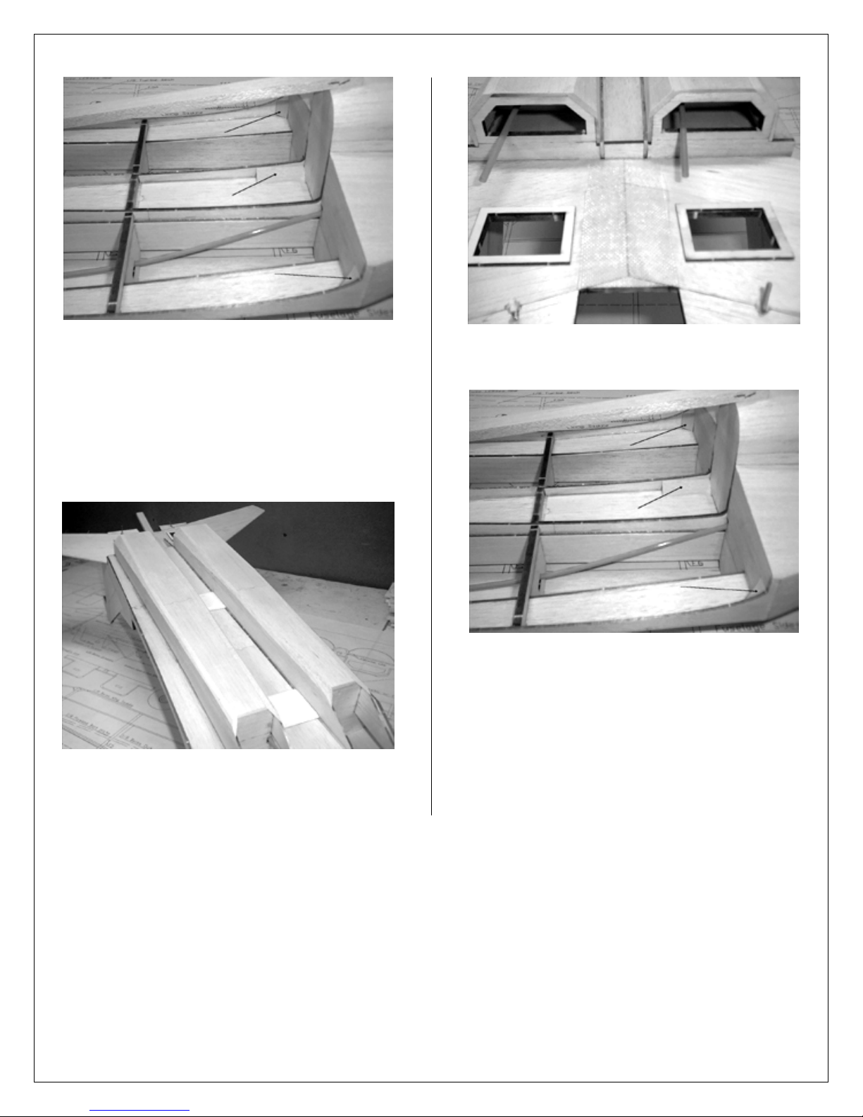
• Take rear part of vertical fin and cut groove to epoxy
torque-rod. Bend rods as per plans and lubricate as you
did before. Place them in epoxy filled groove, pin it to
wax paper covered BB, fold wax paper over and pin scrap
wood next to epoxy groove. It will hold epoxy in place
giving you good surface. Push rods toward the scrap
wood and place 1/8 shims under the rod to help it center
in epoxy Let it dry 15-20 min. and move rods to brake
them loose from epoxy.
• While epoxy is curing, take a ruler and mark a straight
line to help locate positioning of the torque-rod assembly.
• Epoxy torque-rod assembly in place keeping it tight to
vertical fin and stabilizer. Also, make sure you pin it in
place vertical to stabilizer.
• Plank sheet tail pipes. You will need 36 strips 7- 1/2”
long 1/8 x 5/16. It is very simple if you follow few rules.
Start from the bottom; glue one strip at a time. Tip:
always glue it first to F8 until you come to angle ended
strips (you would want to place all strips half way on to
F8 and keep them aligned, except bottom row). Second:
tack glue it in the middle and finally to F9. Third: Use CA
accelerator to move along faster. Do not worry about
small imperfections at this time, you will correct it later.
• Once angled strips needed, place them over the area, mark
and cut. Then push slightly in tack glue angled end and
then glue to F8.

MIG-29 FULCRUM by AK Models.
11
• Once all strips are in place, sand first and run Thin CA at
seems. Sand once again and trim ends of strips at F9.
• Make filler blocks. Cut of 6 1/2” from 1x3/8x36 (Wing
L.E.). Use plans as a guide, but keep in mind rounded
surface of tail pipes. Trim little at time until it fits well.
Round rear part of filler block.
• Glue blocks in place. Use 30 min. Epoxy. Keep blocks in
place tight to vertical fins, pin down and check vertical
fins for 90 deg. to stabilizer.
• From one 1/2x3/4x5 1/2” balsa block make tailbone using
plan and picture as a reference. Do not glue until tail and
tailbone is covered.
• Using plans make fuselage transition from 1x1x7 balsa
block. Make them by diagonally cutting block in halves.
Trim as needed, create rod clearance, glue in place. Also,
glue in 1/8 scrap wood below vertical fins where they
meet bottom sheeting.
• Install engine mount and engine, also use 3/32 scrap wood
to space spinner from F0 by tack gluing 3 strips to back of
spinner and centering F0 on it. Install back plate with F0
on to engine. See next picture.
• Install Top, left side and bottom of cowl. Trim them for
3/16 corners.
• Measure and cut 3/16 corners, glue in place to top-left and
bottom left of F0 and F1. See picture.

MIG-29 FULCRUM by AK Models.
12
• Remove engine glue 1/8 scrap wood to right side of F0
and install 3/16 corners on the right side. Trim corners to
form cowl.
• Enlarge opening for your engine. It will take
approximately half of 3/16 corners. Sand sheeting around
F0 to match spinner.
• Hinge and install elevators as per plans. Sand L.E. as well
as round outer side and T.E.
• Hinge and install rudders as per plans. Sand L.E. as well
as round L.E.
• Make push-rod openings on sides of tail cone. Cut them at
the seam and up. Do not make them too big at this time;
you can enlarge them later during actual rod installation.
• Finish sending fuselage to shape using plans.
Wing construction.
• Measure and cut four wing spars from harder 3/16x3/8x36
sticks. Measure and cut four spar doublers from 3/16x3/8
sticks. Glue together making top and bottom, left and
right spars.

MIG-29 FULCRUM by AK Models.
13
• Cover plans with wax paper and pin bottom spar to BB.
Using a straight edge assemble a wing jig from laser
parts. Pin down wing jig with wider end at W1 rib. Place
all ribs and pin down. Place top Spar in place. Adjust all
ribs (except W1) so they vertical to BB and glue to
bottom spar first and then to top spar. Use W1 Guide
placing it by W1 rib in W1-W2 bay.
•
• Cut off fuse extensions flush to F8. In addition, cut off 1”
from front part of extensions. Put them aside.
• Mark Tail pipe base lines on F9s over the plans so grain
goes vertical. Glue them in place keeping 90 deg. to tail
pipe base.
• Cut four 7 1/4” long 1/8x1 balsa. Position in place and
glue to F8, stabilizer and F9. Once glued to stabilizer,
make a relief cut (not all the way through) approximately
2” long in the middle of sheeting starting from the F9 end.
It will make it easier to round it over F9. See picture.
•
• Pin 3/32x1x36 to all ribs, use straight edge to determine
placement. Glue in place with thin CA running it from rib
and front of rear sheeting.
• Sand front of ribs as needed to install 3/8x1 L.E. Place it
on BB at W9 and centered on W1. Glue in place. DO
NOT TRIM LEADING EDGE UNTIL WING IS
COMPLETED. IT WILL SET WASHOUT ANGLE
ONCE WING IS TURNED OVER.
• From 1/16x3x36 sheet cut sheer webs for all rib bays.
Glue in place, trim tops if needed.
• From 3/32x4x36 sheet measure and cut L.E. sheeting. Use
thin CA to glue to L.E. first, then run Med. or Thick CA
on all ribs and main spar. Use long sending bar to push
down along main spar to let glue set.

MIG-29 FULCRUM by AK Models.
14
• From 3/32x4x36 cut center sheeting starting from rear
sheeting going forward. Use scrap 3/32 from L.E.
sheeting to finish front part. Glue in place one at a time.
• Cut 3/32 rib caps and glue in place. Sand sheeting and
caps, as well as trim sheeting at W1 and W9.
• Unpin wing and flip it over. Pin building jig to BB, place
wing and pin securely down. You will need to force wing
down a little at W9 to pin it to building jig.
• Place 1/4x1x36 as shown in picture. Mark its length as
well as rib’s height. Cut as marked and glue in place.
Sand to match ribs profile.
• From 3/32, make L.E. sheeting and glue in place as you
did before. Glue 3/32x1 sheeting in place. Epoxy vertical
Bass block to W2 as well as grooved L.G. mount. Use
plans to cut 3/16x3/8 leftovers to make hatch support rails
and glue them to W3 and W4. Also, make (from half of
8x11 sheet) paper tube and glue it to ribs.
• Sheet center starting over the L.G. mount. Then rear of it
and in front. Glue cap strip next to hatch side.

MIG-29 FULCRUM by AK Models.
15
• Use long sending bar, to sand slightly rear sheeting and
ribs. Glue 1/4x1” T.E. to rear of the wing.
• Trim L.E. and T.E. at this time. Glue oversized W9A to
W9 rib placing it centered over the W9 rib. Do not trim it
at this time.
Ailerons.
• Cut Aileron Base from 3/32x4x36 sheet. Pin it over the
plan. Measure and cut 3/8x3/4x36 to make a L.E. Pin in
place and glue with Thin CA.
• Unpin Aileron from BB and pin it to wing. Mark L.E. of
aileron to be cut. Place aileron on the edge of the table or
BB and cut as marked.
• Pin it back to plans and glue 1/8x1/4 L.E. to aileron base.
Cut all ribs from scrap wood as per plan and glue in place.
Also, make a horn block from aileron’s L.E. leftovers,
glue in place.
• Sand aileron to shape using a long sending bar.
Temporary hinge aileron to wing. Trim aileron’s L.E. as
per plan as well as T.E.
• REPEAT ALL STEPS ABOVE FOR LEFT WING
(EXCEPT: PAPER TUBE SHOULD ONLY BE
PLACED FROM W2 TO W3).
Join wings.
• From 3/8x3/4, leftovers cut three 1” long blocks. Trim
two of the to 5/8 high. Pin them as shown on the wing
plans at W9’s and at W1 T.E.
• Try-fit wing halves together. Sand as required to get good
contact between W1’s. Use plenty of 30-minute epoxy on
both W1’s and place wings together. Pin L.E. crossway as
well as T.E. Ad masking tape to keep wings tight to each
other. Place wing assembly over the plans making sure it
sits nicely on all three blocks. Let dry before moving.

MIG-29 FULCRUM by AK Models.
16
• Measure and draw Cutoff line on both wings, top and
bottom. Use razor saw to cut 1/8 in front of drawn line
half way through the wing. Flip wing over and finish the
cut. If you do not get it cut completely off, carefully brake
off some sheeting from cutoff part, so you can see what is
holding it.
• Test fit wing to fuselage. Use 1/4x3x12” balsa sheet to
figure out exactly how much to trim off. Finish trimming.
You should be able to place wing on to fuselage and place
what will be front brace in place between wing and F4.
Before you glue front brace, cut 1/4x1 to fit as shown:
next to W1’s and tight to top and bottom sheeting.
• Permanently glue 1/4x3x12 1/2” (front brace) in place by
placing wing right side up and flat on BB.
• Flip wing over and trim bottom part of the front brace
only also round edges to fit well in to wing saddle. Do not
trim topside of front brace.
• Place wing on to fuselage; check for good fit trim as
needed. Draw LERXes lines on front brace. Remove wing
and connect ends of both lines at F4. Cut as marked and
leave untrimmed.
• Glue rear braces as per plans placing it even with top
wing sheeting at outside ends.

MIG-29 FULCRUM by AK Models.
17
• Apply fiberglass cloth to top and bottom of the wing.
• Epoxy wing bolt plates as per plans (note the difference).
• Drill 3/8 holes using wing bolt plates as a guide. Place
something under the wing so you do not damage the
bottom sheeting.
• Push blind nuts in place to leave impression from 3 teeth
on wing bolt plates. Drill at this marks 1/16 holes.
• Center the wing on fuselage, check for perfect alignment
with stabilizer. Double check and pin wing down to
fuselage.
• Push blind nuts back in place and screw bolts until bolt
hits bottom sheeting of fuselage from the top to determine
where to drill holes in bottom wing bolt plates.
• Center the mark on fuselage bottom (side to side). Drill
using 3/16 bit at this marks.
• Insert bolts from fuselage bottom this time, place wax
paper as shown and place wing in place. Apply epoxy
around blind nuts (you do not want to get them loose!)
and tighten the bolts. Mark bolts length to be cut.
NEVER USE POWERED SCREWDRIVER TO
TIGHTEN THE BOLTS.
• Place F4A and F6A in place and trim as needed (trim
bottoms). Glue F4A and F6A right next to F4 and F6.
• Measure and cut top 1/8 sheeting and pin in place. Place
F5A in the middle of top sheeting. Pin sides in place and
move F5A to where it fits best. Glue everything in place.
• Remove wing from fuselage. Trim 1/8 top and sides for
3/16 corners. Measure and cut corners, glue them in place
aligning at the bottom for easy trimming. Sand corners
flush with top and sides as well as flush with F4A and
F6A.

MIG-29 FULCRUM by AK Models.
18
• Position wing back to fuselage with wax paper at front
and rear of the wing and round corners to match front and
rear of fuselage.
• Using scrap 3/32x1 from rear wing sheeting cut sheeting
support to be placed next to F6’s and go up to 3/32-
fuselage sheeting.
• Measure 4” from F6 going forward and mark with line.
Also Use ruler to draw line as extensions of vertical fins.
Cut 3-1/4” long ribs from 3/32 scrap. Place them as
shown in the picture and glue in place.
• Use 3/32x4” wide scrap from wing’s front sheeting, fit in
place and bevel 3/4” at bottom side. Glue in pace.
• From 3/32” scrap wood, cut front transition. It should be
3/4” on outer side and 1-3/4” on inner side. You can ad
very small piece of scrap wood to make a rib at outer end.
• Trim plastic humps to fit well on to no-sheeted parts of
F8’s and on 3/32 fuselage sheeting. Then hold humps
down and trim tail pipes sheeting to make smooth
transition. Do not go too far sending, 1/2 - 3/4 should be
enough to round up.

MIG-29 FULCRUM by AK Models.
19
• Glue 1/4x1/8x4 rails along bottom of humps; trim them so
they would lay flat on the sheeting. It will help gluing
humps to the fuselage sheeting. Do not glue them in place
yet.
• Mark 1/8 back from F1 to indicate hatch’s front, mark 1/8
forward of F2 as well. Than using seems as a reference
line mark centers of 3/16 corners to make hatch’s
sidelines.
• Carefully cut out hatch using razor saw for front and rear
line cuts and knife for sides, cut sides vertical to 3/16
corners. Glue hard balsa support for front of the hatch.
Note foam insert that holds fuel tank parallel to thrust line
and in alignment to carburetor.
• Measure 5/16 from inboard end of L.G. mount and drill
5/32 in to vertically positioned bass wood block.
• Also, make an opening for servo wires on the bottom of
left wing as shown on the picture above.
• Temporary install ailerons and pin straight piece of scrap
wood to ailerons and rear wing sheeting at W8.
• Trace ailerons to W9A, and trim as needed. Place wing
tips in place, pin and trace W9A on to it. Remove and
trim as needed. Glue them in place and sand to final
shape.

MIG-29 FULCRUM by AK Models.
20
• Glue support rails flush to insides of cockpit area and
sheet with 3/32 scrap wood keeping grain crossways.
• Basic construction is complete at this point. Go back and
final sand everything.
HARDWARE INSTALLATION
• Install front gear wire and steering arm with easy
connector. Install pushrods with 2/56 rods on both ends of
flex inner rods for steering and throttle control.
• Install elevator servos and make their push rods.
• Install rudder servo and connect it to rudder torque rods
with one 2/56 rod. Use SIG easy connector. Also make Z-
connection to steering push-rod (cut two of “four way”
servo arms off) leaving one that closer to tail pipe
sheeting.
• Connect throttle servo to throttle push rod with adjustable
cleaves.
• Epoxy push rods housing to all formers they go through.
• Use basswood from L.G. installation to make servo
blocks for aileron servos. Glue them to servo hatches and
install servos.
• Install hatches with servos, install control horns on
ailerons and make push rods.
• Before you install engine, do not forget to fuel proof nose
section, firewall and fuel tank area.
• Install engine and connect throttle push rod. Check for
smooth operation.
• Install fuel tank, use foam around it to reduce vibration as
well as to keep it in-line with thrust line.
• Trim and install canopy. Use eight screws to hold it in
place. Also, use electric tape to outline edges of the
canopy.
• BALANCE your plane once all the hardware is installed.
Move battery pack around to determent best position to
achieve correct balance. Once correct CG is achieved,
balance model laterally (side to side). CG location on the
plan is best for a test flight and getting used to the model
Table of contents
Popular Toy manuals by other brands

Bachmann
Bachmann THUNDERBIRDS AiP10002 quick start guide

Eduard
Eduard Jaguar GR.1 exterior manual

ZEIA
ZEIA PHANTOM FX-61 instructions

The Learning Journey
The Learning Journey Techno Gears Marble Mania Whirler instruction manual

Mi
Mi Lutema MIT35RMHB instruction manual

Fisher-Price
Fisher-Price DALE EARNHARDT JR L6345 Owner's manual & assembly instructions

Micromagic systems
Micromagic systems MSR-H01 Assembly guide

NATURE & DECOUVERTES
NATURE & DECOUVERTES 42001510 manual

The Learning Journey
The Learning Journey Techno Gears Marble Mania Zany Trax 2.0 instruction manual

Eduard
Eduard Jaguar A exterior quick start guide

Marvel
Marvel Avengers Iron Man quick start guide

REVELL
REVELL Out Speeder instructions