AKA Berkut 5 User manual

1
Berkut-5
VERSION 5.01
DISCRIMINATING METAL DETECTOR
OPERATING INSTRUCTIONS

2
GENERAL INFORMATION .............................................................................................. 5
INCLUDED IN KIT... ....................................................................................................... 5
TECHNICAL CHARACTERISTICS.................................................................................... 6
INTRODUCTION............................................................................................................. 7
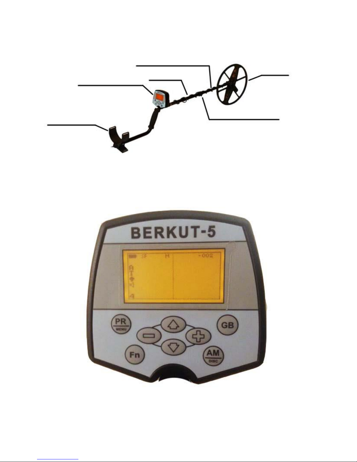
ASSEMBLING YOUR BERKUT 5...................................................................................... 8
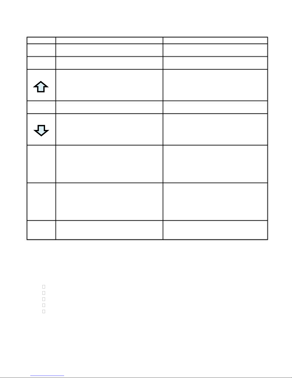
THE FRONT PANEL......................................................................................................... 9
THE BACK PANEL... ....................................................................................................... 10
THE DISPLAY... ............................................................................................................. 11
STARTING UP THE DEVICE........................................................................................... 12
THE START MENU... .................................................................................................. ... 13
GROUND BALANCING................................................................................................... 15
ADJUSTING KEY PARAMETERS... ............................................................................. ... 17
ADDITIONAL PARAMETERS... .................................................................................. ... 19
THE SOUND MENU... ..................................................................................................... 20
THE DISPLAY MENU... .............................................................................................. ... 23
THE SEARCH MENU....................................................................................................... 25
THE DISCRIMINATION MENU...................................................................................... 27
THE OTHER MENU..................................................................................................... ... 28
THE COIL MENU... ..................................................................................................... ... 30
DYNAMIC AND STATIC OPERATING MODES... ............................................................ 31
DISCRIMINATION MODE OF SEARCH.......................................................................... 32
THE DISCRIMINATION MAP... ..................................................................................... 32
MODE TEACH DISCRIMINATION... .............................................................................. 34
SECTOR FOR THE SPECIAL SIGNAL... ...................................................................... ... 34
OVERLOAD MODE... ...................................................................................................... 35
USER PROGRAMS.......................................................................................................... 35
REPLACING THE SEARCH COIL... ............................................................................. ... 37
BATTERIES................................................................................................................ ... 37
USE OF HEADPHONES... ............................................................................................... 38
PROGRAM ADJUSTMENT OF COILS........................................................................... 38
ADJUSTMENT OF THE NEW COIL FOR THE CURRENT PROFILE....... .......................... 39

3
ADDITION OF THE NEW COIL ON NEW PROFILE... .................................................... 40
STORAGE AND SERVICE OF YOUR DETECTOR............................................................. 40
SOME THOUGHTS ON USING YOUR NEW DETECTOR.............................................. . 42
SCANNING TECHNIQUES... .......................................................................................... 43
ABOUT GROUND BALANCING ................................................................................. ... 43
IDENTIFICATION OF DIFFERENT TYPES OF OBJECTS........................................... ... 44
USE OF THE PINPOINT MODE... .................................................................................. 45
USING THE EQUALIZER ... ....................................................................................... ... 46
EXAMPLES OF VDI........................................................................................................ 46
GUARANTEE CERTIFICATES... ................................................................................. ... 47
ACCEPTANCE CERTIFICATE... .................................................................................. ... 47
34

4
GENERAL INFORMATION
Metal detector BERKUT 5 is designed to search for and identify metal objects in the dielectric
(dry sand, wood, etc.) and low conducting media (soil, brick walls, etc.).
Some applications of use are:
•Criminal;
•Engineering;
•Housing and community services, construction and fire-fighters to search for underground
utilities, pipelines, cables, manhole wells etc.
• Archaeology and treasure search.
The device is designed to operate under the following conditions:
-Ambient temperature from -20 up to +50°c (-4 to 122 F);
-Relative humidity up to 98 per cent at temperature of 25°c (77 F);
-Atmospheric pressure from 630 to 800 mm Hg.
INCLUDED IN THE BOX
CONTROL BOX
COIL
TELESCOPIC POLE
INSTRUCTIONS
SHIPPING CONTAINER
HEADPHONES *
CARRY BAG*
COVER FOR CONTROL BOX*
*- if purchased seperately
5

5
TECHNICAL CHARACTERISTICS
The maximum range
Detection:
Indication modes:
Search modes:
Power supplies:
Consumption current, мА:
The maximum time
Continuous work,
Hour:
Brass disk in diameter of 25 mm - 45 cm;
Large objects - 250 cm;
Audio with up to 91 tones;
Visual (the LCD display with the permission
128х64 points);
All metal;
Discrimination;
Pinpoint
4 elements (or the accumulator) АА; a
current of the gauge 1 - 100;
Current of the gauge 2 (TURBO) - 220;
Current of the gauge 1 - 27;
Current of the gauge 2 (TURBO) - 12;
Overall dimensions, mm: a telescopic bar - 1100-1300 X 200;
The electronic block - 110 X 105 X 68;
Weight of the device, kg: -1,3.
Notes. The Maximum range of detection - the greatest possible distance
Detection of object in the absence of external hindrances for the gauge DD260 -
7кГц.
The
Current of consumption and time of continuous work - in the absence of sound
Indications and with the switched off illumination of the display at use of
accumulators, capacity 2700 mA-ch.
Weight of the device with stock coil
6

6
INTRODUCTION
What is the hodograph and why is it so important? The received signal is characterized
not only by its amplitude and phase, but it is also a vector quantity. Amplitude and phase
depend on the electro physical parameters of objects such as conductivity, magnetic
permeability, depth, geometry, etc.
In order to accurately describe the nature of the received signal from an object is very
difficult, given the variety of influencing factors. However, it is possible to point out some
general patterns. Earlier, we mentioned that the signal is a vector quantity characterized
by amplitude and phase. If you hold any metal object to the coil it is evident that the
magnitude of this vector will vary. The end of the vector will describe, on a coordinate
plane, some shapes (lines, loops, etc.). These shapes are called Hodographs. The latter
most closely describes the complex interactions of the coil with metal objects.
When analyzing the hodographs remember a few general rules:
• Hodographs of small and medium-sized ferromagnetic objects are in the left quadrant
(i.e. have a negative vector angle);
• Hodographs of objects of non-ferrous metals and large ferromagnetic objects lie in the
right quadrant (positive vector angle);
• The larger the area of the surface of an object the higher the electrical conductivity,
hence the greater the slope of the hodograph to the right;
• Travel times of medium and large ferrous objects, as a rule, have the shape of a loop;
• Hodographs of non-ferrous metal objects are mainly straight;
• A properly ground balanced unit will have a vector along the horizontal axis. Examples
of the hodographs of some objects are shown in Fig. 14. Thus, analyzing the shape and
position of the hodograph, along the coordinate plane, there can be a certain degree of
probability as to the identity of the object type.
Examples some objects are resulted in a Fig. 1:
Fig. 1
It should be noted that the hodograph examples given are idealized and do not take into
account the effect ground mineralization.
7

7
In actual practice the shape of the graph will be defined as the vector sum of signals from
the ground and detected object. For example, a coin taking into account the influence of
ground minerals can look as follows (a Fig. 2):
Fig. 2
The stronger the ground minerals the greater the affect and deformation it will have on the
targets signal and shape on the Hodograph (loops verses a straight line or arrow)
ASSEMBLING YOUR BERKUT 5
Remove the detector from the box. When shipped the detector and parts should
look like Fig. 3.
Fig. 3
Assemble the Detector. For this purpose:
Remove the detector rod from the box;
Remove the electronic control box from the shipping box;
Install control box on upper portion of the rod by sliding onto the installed tab;
Install supplied coil on the lower rod. Tighten coil bolts snug. Do not over tighten;
Wrap the coil wire around the rod insuring the wire does not hang lose. Loose coil
wires may cause false responses.
Connect the coil to the socket on the rear of the control housing.
Remove battery compartment cover and install batteries;
Close back cover.

8
ATTENTION! DO not over tighten the plastic locking collars on the rod as well as the plastic
Coil bolt.
Once assembled your detector should look like Fig. 4.
Plastic rod
The control box
Armrest
Bar
Fig. 4
The coil
Plastic locking collar
THE FRONT PANEL
Appearance of the front panel is shown in a Fig. 5.
Fig. 5
89

9
Buttons have following appointment:
The
PR
MENU
GB
AM
DISC
-
+
Fn
Short pressing
Switch between User programs
Access Ground Balance Mode
In the standard search mode activates
Pinpoint mode.
In Menu operations moves cursor up.
Turns Discrimination Mode On/Off
In the standard search mode used to
quick access the key parameters in
the menu “search”.
In Menu mode used to move cursor
down.
In standard search mode decreases
value of last key parameter accessed.
In Menu decreases the value of the
current selection
In standard search mode increase the
value of the last key parameter
accessed.
In menu increases value of current
selected parameter. In the case of
Equalizer + will access settings
User assigned functions to this button.
Analog mode, Turbo, Economy mode,
Backlight
Long pressing
Access main menu.
Access Coil Menu for selecting and
adjusting installed coils.
Access the Menu “Display”
Access the Menu “Discrimination”
Access to Menu “Other”
Access the menu “Audio”
Access the Menu “Search”
Input in the menu of adjustment of
action of the button [Fn].
THE BACK PANEL
On the back panel of the electronic block (Fig. 6) are located:
The battery compartment;
On/Off switch;
Coil connector socket;
Headphone Jack;
Serial Number.
10

10
Headphone jack 1/8”
Battery
Compartment
On/Off switch
Coil Socket
Serial number
Fig. 6
The on/off switch has multiple function other than just turning the detector on and off.
These “other” functions can be set in menu “Other”.
THE DISPLAY
The Berkut 5 LCD display as shown in fig 7
A
T
S K M An
TURBO -003
+47
3 sensitivity: 15
Fig. 7
In normal operating modes the display will indicate the following:
Hodograph of the detected object;
Current User Program in use;
device operating mode:

11
A- a mode all metals
D- the discrimination mode is enabled
V–When discrimination mode is enabled will
indicate when Visual discrimination is on
Level of a charge of the battery;
T–Indicates AGB is enabled (at fine tuning carrying out
With some time it is replaced on R);
Index number of target VDI;
Level of a signal from object (a column on the right);
The menu of key parameters;
S- filter SFT is enabled;
K- the suppression filter of large objects is enabled;
M- the suppression filter of small objects is enabled;
An –Analog mode is enabled;
TURBO - the TURBO mode is enabled;
Indicates headphones installed.
Indication of value of current ground balance (-003)
STARTING UP THE DEVICE
Prior to turning on your detector please read the instructions thoroughly. Upon
every startup of the detector there is a calibration of the detector in air.
It is necessary for fine tuning of electronic parameters to the surrounding environment.
Therefore it is crucial to perform the following on every startup:
Hold the device firmly in your hand and if possible use the supplied armstrap to
steady the device
Lift the coil to waist level;
Be sure you are clear of any large metal objects within 6 feet;
Turn the power switch [ON].
Upon powering up on the display there will be information regarding the currently
installed coil, quantity of available calibrated coils, the version and date of the
software, and as the help on functions of buttons in the inclusion menu (a Fig. 8):
The gauge: D6x10-14 1
The version : 5.00
Date : 28.05.2012
[ПР]-RESET
[+]–COIL-SETUP
[Fn] –START MENU
Fig. 8

12
If device startup has passed successfully, the device will play a melody and will
enter into the search mode (a Fig. 9):
S K M An TURBO -003
A
T
3
Fig. 9
Otherwise, after a warning melody, there will be a warning as shown in a Fig. 10:
THE COIL IS NOT
COMPENSATED.
REPEAT COMPENSATION
Fig. 10
In this case switch off the device and repeat coil compensation in a different place
(Having previously determined the absence of any metal objects). If compensation still does
not occur, after insuring there is no presence of large metal objects, check to make sure the
coil connector is seated correctly and the proper coil is installed. If this has been verified
and compensation is still not established the device will need to be returned to the service
center.
Device power off is carried out by pressing the power switch to the down or off
position.
Once the switch has been turned off the device may take up to 10 seconds to
completely shut down as settings are stored into the internal memory.
THE START MENU
At device power on it is possible to enter certain key startup parameters without
waiting for the system to perform coil compensation. As displayed in fig 8 these are
12

13
Factory Reset, Enter Coil Setup, and Start Menu.
To access the startup menu press and hold [Fn] (a Fig. 11) while turning on the
device.
Start Menu
Factory Reset
Select Coil
Coil Setup
Add Coil
Battery: Alkaline
Fig. 11
In the inclusion menu following functions are accessible:
Factory Reset. By pressing the button [+] the factory values will be reset
Note that parameters of the adjusted coils thus remain (a Fig. 12).
ATTENTION!!
Resetting the factory
Settings
Fig. 12
To choose Select Coil. By button pressing [+] the select profile of coil menu
appears (a Fig. 13).
Select profile
Of coil
D9x12-14
[], [ ] - select
[+] - enter
Fig. 13
13

14
To choose the coil profile desired press the buttons or
To select the profile activation press button [+].
To Adjust the coil. By pressing the button [+] the program enters the
automatic adjustment of the coil for the current coil profile selected.
To Add the new coil. By pressing the button[+] enters the program of automatic
adjustment of the selected coil profile (a Fig. 14).
Select Profile
Of coil
D9x12-14
[], [ ] - select
[+] - enter
Fig. 14
The choice of a profile of the gauge is carried out by buttons or , to start
automatic adjustment of the coil press the button [+].
Battery. Selects the type of batteries installed (p. 29).
GROUND BALANCING
Proper ground balancing is necessary in order to reduce the effects of ground
minerals on the detector. Without proper ground balance the detector cannot operate
to its full potential and can be subject to false signal from ground minerals.
To carry out a proper ground balance perform the following procedures:
1. Locate an area of ground that is free from any metal targets within a 4 foot diameter.
Use standard search mode with no discrimination to help locate clean ground;
2. Lift the coil to around waist level and
3. Press the button [GB]. The device will enter the automatic ground balance mode
( Fig. 15):
1415

15
М=002 БГ: +003
A Fn: +180
Fig. 15
In the right top part of the indicator the phase of balance of a ground is
represented in Degrees.
On top left –The level of ground mineralization in standard units.
On bottom left - Ground balancing mode (A - Automatic, Р-Manual).
4. Slowly and smoothly lower the coil to the ground avoiding touching grass,
stones, etc. Lower the coil at a speed of 1 to 2 seconds from the raised to
lowered position.
Upon lowering the coil to the ground, on the display, will appear a line in the
screen left-hand side (a Fig. 16). Lower the coil until the line reaches the display
left edge.
М=102 БГ: +005
AD Fn: +180
Fig. 16
5. At successful balancing, the device will play a melody
6. Press the button [GB] for transition to standard search mode;
7. If ground balance was not successful raise the coil waste high and wait 2-3 seconds
( ground line will retract to a small circle in center of screen). Repeat steps 4-6.
To enter the manual ground balance mode press either the + or - buttons. This
will allow you to adjust the ground balance point achieved in the automatic ground
balance procedure. The automatic GB procedure will be turned off and parameter
SPEED AGB will now be set to OFF. To return to previously set Speed AGB values
either perform automatic ground balance procedure again or simply access Speed AGB

16
in Search menu and set to preferred value (p. 28).
If, after carrying out the ground balance procedure, the value of БГ differs greatly
from zero this may can cause an incorrect installation of the phase parameter of the coil.
To reset this value to zero simply press the button.
ADJUSTING THE KEY PARAMETERS
Access to the key parameters is carried out from the main search mode by simply
pressing the button. Once pressed, in the bottom left corner of the display, will appear
the parameter and its related value as seen in fig 17 (gain:15)
S K M An TURBO -003
A
T
3 GAIN:15
Fig. 17
With each subsequent pressing of the button there is a transition from
one parameter to another. Changing the value of a parameter is carried out
by using Keys [-] and [+].To decrease the value of the parameter setting press [-] and to
increase its value press [+] . If, after approx. 15 seconds, there are no further changes
made the key parameter settings will disappear and return to the normal search screen. The
last adjusted parameter is stored in memory and by pressing the + or –button will recall
this last adjusted and its value will change according to whether you pressed the + or-
button. Note that this quick access is only available if the detector does not have the
discriminator training mode enabled. If the discriminator training mode (teach mode) has
been enabled than the + and –buttons perform different functions when pressed in standard
search mode ( no key parameters displayed). In order to access the key parameters one will
have to press the button to first access the key parameters then make the appropriate
+ or - corrections
Adjustment key parameters concern:
CC –Current to the coil,
АT –Audio Threshold,
IT –Identification Threshold,
GN –Gain (Sensitivity),
RS –Recovery Speed
Further details on each of these parameters are now considered. The range of each
parameters settings are within the square brackets []
16

17
COIL CURRENT (CC) [1- 2] Sets the level of current supplied to the coil. At
A setting of 2 (TURBO) maximum current is applied to the coil. Maximum depth
ability is achieved however operating time is decreased due to increased battery
usage. At the minimum setting of 1 maximum battery time is achieved at the cost of
reduced depth.
The remark. If operating near sources of electrical interference or other detectors
it is advised to set CC to 2 (turbo) and reduce sensitivity in order to reduce these
affects. On the other hand it may be necessary to reduce CC to 1 in order to
minimize the interference on other devices close by.
RECOVERY SPEED (RS) [1- 9] defines speed of the automatic tuning under
ground conditions in the dynamic mode (This setting has no affect in the pinpoint
or static mode). Reducing the speed of auto will increase the depth of search.
However in areas of considerable ground mineralization, target ID reliability can
worsen. There can be false responses from the ground, and also separation of the
closely spaced targets worsens. Lower settings of the recovery speed are
recommended for areas with deep targets, areas with low mineralization and areas
with little metal trash. It is also important to use a slower steady sweep speed
avoiding erratic movements, jerking etc. as well as keeping the coil parallel to the
ground. Increase in recovery speed settings is recommended for areas with many
closely spaced targets where target separation is most important. It is not
recommended to set the RS below 5.
AUDIO THRESHOLD (AT) [0- 20] defines the minimum signal level required to
generate an audio response on a detected object. Reducing the Audio Threshold
setting increases the sensitivity to small and deep targets but also increases the risk
of false audio responses. The device will react to the smallest particles of metal as
well as possible ground mineral concentrations. To achieve maximum depth of
search set the Audio Threshold as low as possible without creating excessive false
responses from the ground. Increasing the Audio Threshold will improve the
comfort of search by reducing false ground responses but at the expense of
reducing depth sensitivity. Unless there is a special reason to do so, do not set
the level too high as a loss in response sensitivity to large nonferrous items can
occur.
GAIN (GN)[0- 20] Defines overall sensitivity of the metal detector. The higher the
Gain the deeper the ability of the detector as well as increased response from smaller
targets. To achieve maximum depth and target response set the gain as high as
possible while still maintaining a stable detector. In areas of excessive ground
minerals or areas with a lot of metal trash it will be necessary to reduce gain levels
to a lower level. It is not recommended to set the gain to the maximum level
especially in areas with mineralization as performance will decrease at these
excessive settings. In most cases a maximum setting of 16 is recommended to avoid
false responses.
IDENTIFICATION THRESHOLD (IT) [0- 20] Defines the minimum signal level
required to generate a target ID audio response as well as to display a VDI value. If
a target is detected but does not meet the minimum signal level an audio
response from the threshold will be heard but no VDI number will be displayed.
Lower values will increase the depth response for target ID but reliability as well
1
7

18
as stability of the VDI will worsen. At increased settings depth of target ID will be
reduced but VDI reliability and stability will increase. At a setting of 0 the device will
identify a target immediately but on deep or weak targets the probability of error greatly
increases.
ADDITIONAL PARAMETERS
Access to additional parameters is carried out by means of the branched menu. All
parameters are grouped in a separate submenu. Access is possible both from the main menu
and by means of fast access by long pressing of the corresponding buttons in normal search
mode.
The input in the main menu is carried out by long pressing (more than one
second) the button [PR/MENU] ( Fig. 18).
MAIN MENU
Audio
Display
Search
Discriminate
Other
Coils
Fig. 18
Parameters are broken into the following groups:
Audio
Display
Search
Discriminate
Other
Coils
To select a sub menu option scroll to the selection using the or then to
enter the menu press+.
20

19
THE AUDIO MENU
Audio Pag1
Volume: 10
Equalizer:
Volume S.S.: 8
Keys sound: On
Border Fe: -15
Num. of tones: 91F
Fig. 19
Audio Pag2
Sound freq: 5
Length fe: Short
Overload vol: 8
Sm signal vol: 4
Thresh volume: 0
Fig. 20
Under the Audio Menu section are available the following parameters for adjustment:
VOLUME[0-10] Sets the overall audio level of the detector.
EQUALIZER Allows the user to set unique volume levels to 12 different VDI
groups. The audio level is adjustable from 0-17 for each group. When the level is set
to 0 there is no audio response while a setting of 17 is maximum audio response. To
enter the Equalizer adjustment mode press the button [+]. On the screen will
appear the Equalizer menu for adjustment (a Fig. 21):
21

20
Equalizer
17
+6: +21
Fig. 21
The cursor under a column specifies which sector is currently selected. On
the bottom right is displayed the VDI range for the currently selected group. The
column height corresponds to the volume level of the currently selected VDI
sector. A numerical value of the volume level is also displayed above the selected
VDI group. The choice of sector of adjustment is carried out by keys [-] and [+],
while adjusting the audio level is performed by using the and keys.
VOLUME of SERVICE SIGNALS [0... 10] Sets the volume level of service signals
such as the pressing of keys, successful ground balance, the melody played upon
successful coil compensation etc.
KEYS SOUND [ON/OFF] Enables or disables sounds made while pressing any
keys (buttons).
Border Fe - [-85 to +85] Defines the VDI border for setting the iron tone. The user
may find this advantageous as the effects of ground minerals can affect the signal
from small non ferrous objects causing them to respond with a negative VDI number.
Thus the user may choose to set the Fe border to a specific negative value to include
these small low conductive targets. Also one may wish to include some small
desirable ferrous objects by adjusting the FE border to exclude these from the Fe
tone. While conversely one may wish to set this value to a slightly positive value
[+10] to include small annoying pieces of foil commonly found in modern sites littered
with trash. Setting is done on a personal preference of the user.
The NUMBER of TONES[1F, 2F, 3F, 10F, 91F] Allows the user to set the number
of available tones .
VALUE 1F- will generate a single tone on ALL targets including ferrous
targets. NOTE: a setting of 1F effectively negates the Border FE setting as
there is no separate FE tone
VALUE 2F-
A low tone will be generated for ferrous targets while a
high tone will be generated for all non ferrous targets. The border for
these tones can be set under BORDER FE option previously mentioned.
VALUE 3F
, A low tone will be generated for small ferrous objects
whose border has been determined by setting BORDER FE. A medium
tone will be generated for targets just above the Border FE setting but
below VDI +15. A High tone will be generated for targets within VDI +15
to +90 range.
22
Table of contents
Other AKA Metal Detector manuals
Popular Metal Detector manuals by other brands

GUARD megadetect
GUARD megadetect 1165190 Operation manual

DR.ÖTEK
DR.ÖTEK MT9s user manual

Fisher Research Labs
Fisher Research Labs F75 Special Edition Comprehensive operating manual & guide

Bounty Hunter
Bounty Hunter Elite 2200 owner's manual

Velleman
Velleman CS300 user manual

Velleman
Velleman CS250 user manual