Akai DDV-805 User manual

Car Multimedia Centre
DDV805
All manuals and user guides at all-guides.com
all-guides.com

2
CONTENTS
Page
Disassembly Instructions ..................................................................................................................................... 3
Disassembly Diagram.......................................................................................................................................... 4
Disassembly Instructions˄TV7020˅................................................................................................................. 5
Disassembly Diagram˄TV7020˅...................................................................................................................... 6
Operation Check.................................................................................................................................................. 7
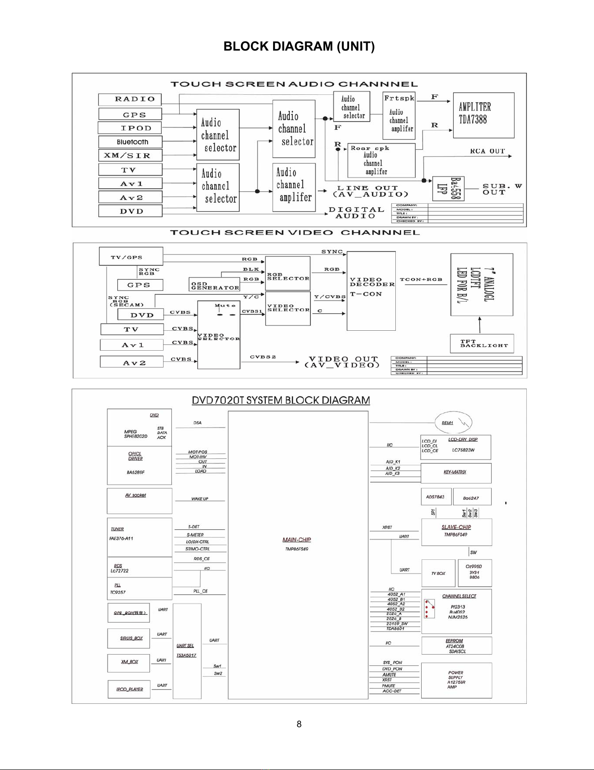
Block Diagram ..................................................................................................................................................... 8
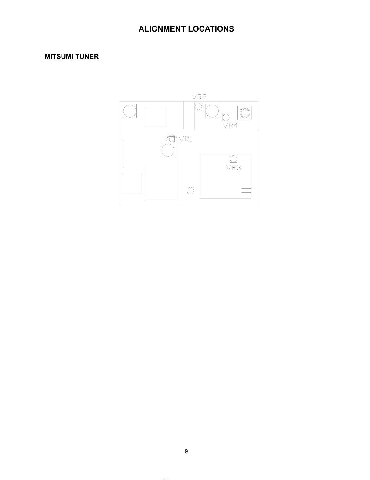
Alignment Locations ............................................................................................................................................ 9
Alignment Procedures ....................................................................................................................................... 10
Printed Circuit Board.......................................................................................................................................... 11
Exploded View (Display).................................................................................................................................... 31
Exploded View Part List (Display)...................................................................................................................... 32
Exploded View (Unit) ......................................................................................................................................... 34
Exploded View Parts List (Unit) ......................................................................................................................... 35
Exploded View (TV7021) ................................................................................................................................... 37
Exploded View Part List (TV7021)..................................................................................................................... 38
Exploded View (Deck) ....................................................................................................................................... 39
Exploded View Part List (Deck) ......................................................................................................................... 40
Schematic Diagram ........................................................................................................................................... 42
Electrical Parts List ............................................................................................................................................ 54
Specifications..................................................................................................................................................... 74
All manuals and user guides at all-guides.com

3
DISASSEMBLY INSTRUCTIONS (UNIT)
1ˊUsing the unlock key that came with the unit or a similar tool, unlock the Mounting Box and remove toward
the rear of the unit.
2ˊTake out the Ring and remove two screws (A) from each side of the base then remove the Base.
3ˊRemove two screws (B) located on the Main Board left side of the side bracket.
Remove two screws (C) located on the Main Board Right side of the side bracket.
4ˊRemove two screws (F) located on the under of the deck front Bracket.
Remove two screws (G) located on the front of the deck front bracket then remove the Deck Bottom
Bracket.
5ˊRemove two screw (H) and the Wire Clip.
6ˊRemove the screws (I) from on the Rear of the under side bracket then remove heat sink.
Remove the screws (J) from on the Rear of the top side bracket then remove heat sink.
7ˊRemove two screws (K) from on the back of the Rear-right Cabinet then remove the DC FAN 12V and
The Fan Cover.
All manuals and user guides at all-guides.com

4
DISASSEMBLY DIAGRAM (UNIT)
All manuals and user guides at all-guides.com

5
DISASSEMBLY INSTRUCTIONS (TV7020)
1. Remove two screws (A) from each of the Top Cover then remove the Top Cover.
2. Remove four screws (B) from on the main board then remove the Bottom Cover and Main Board.
All manuals and user guides at all-guides.com

6
DISASSEMBLY DIAGRAM (TV7020)
All manuals and user guides at all-guides.com
all-guides.com

7
OPERATION CHECK
GENERAL SPECIFICATIONS OF SIGNAL
Standard frequency
Signal output
Modulation
FM
MW
FM
MW
MW
FM Stereo
98.1 MHz (87.5, 108.0 MHz)
1000 kHz (522, 1620 kHz)
1 mV
5 mV
400 Hz 30% MOD.
1 kHz 75 kHz DEV.
46% for L only or R
only pilot level 8%.
AF output level FM/MW
Power source voltage DC 14.4V (Backup voltage is the same as this)
AF load impedance 4 ohm pure resistance
Balance Center position of level
Tone Center position.
The signal strength read in this section is voltage on the antenna.
TestDiagram
4-SPEAKER
VTVM
DISTORTION
METER
2-SPEAKER
FRONT
SPK.
SPK.
FL.
RL.
SPR.
MAIN UNIT
AM SG
VTVM ANTANNA
DUMMY
FM SG
MODULATOR
STEREOS
MPX
ANT
FRONT
SPK.
SPE.
FR.
RR.
4-SPEAKER
SPK.
2-SPEAKER
POWER ANTANNA
ACC (DV14.4V)
GROUND
BACK UP (14.4V)
All manuals and user guides at all-guides.com

8
BLOCK DIAGRAM (UNIT)
All manuals and user guides at all-guides.com

9
ALIGNMENT LOCATIONS
MITSUMI TUNER
All manuals and user guides at all-guides.com

10
ALIGNMENT PROCEDURES
FM ADJUSTMENT
Equipment Required
z
AM IF/RF signal generator
z
Solid-state voltmeter (SSVM)
z
Regulated DC power supply
z
2-CH voltmeter
z
Distortion meter
FM Alignment Using FM Signal Generator
Note: Press the radio power switch to on the radio. Signal generator output must be kept as low as possible
to avoid overload and clipping.
Step Generator
Coupling
Generator Display
Setting
Adjustment Remarks
Stereo
Separation
Signal
Generator
to antenna
receptacle
98.1 MHz
Int. 1 kHz
Dev. 75 kHz
L+R = 90 %
pilot = 10 %
98.1 MHz VR3
Adjust AF
output power
at maximum
separating
more than 30 dB
FM SNC
Adjustment
98.1 MHz
Dev. 75 kHz
L+R=90 %
Int. 1 kHz
60dBμV output
98.1 MHz
@ 40 dBμ
98.1 MHz VR2 Stereo Separation
25 dB (±5 dB)
98.1 MHz
Mod. 1kHz
Dev 75kHz
98.1 MHz VR4
Stop
SENS.
Signal Generator
to antenna
receptacle
1000 kHz
Mod. 1kHz
Mod 30%
1000 kHz VR1
Adjust AF to
stop station.
Note: The tuner module is well-adjust and adjustment is not recommended.
All manuals and user guides at all-guides.com

11
PRINTED CIRCUIT BOARDS
MAIN BOARD
TOP VIEW
All manuals and user guides at all-guides.com
all-guides.com

12
MAIN BOARD
BOTTOM VIEW
All manuals and user guides at all-guides.com

13
KEY BOARD
TOP VIEW
All manuals and user guides at all-guides.com

14
KEY BOARD
BOTTOM VIEW
All manuals and user guides at all-guides.com

15
MOTOR CONTROL BOARD
TOP VIEW
All manuals and user guides at all-guides.com

16
MOTOR CONTROL BOARD
BOTTOM VIEW
All manuals and user guides at all-guides.com
all-guides.com

17
REMOTE BOARD
TOP VIEW
All manuals and user guides at all-guides.com

18
REMOTE BOARD
BOTTOM VIEW
All manuals and user guides at all-guides.com

19
LCD BOARD
TOP VIEW
All manuals and user guides at all-guides.com

20
LCD BOARD
BOTTOM VIEW
All manuals and user guides at all-guides.com
Other manuals for DDV-805
1
Table of contents
Other Akai Car Video System manuals