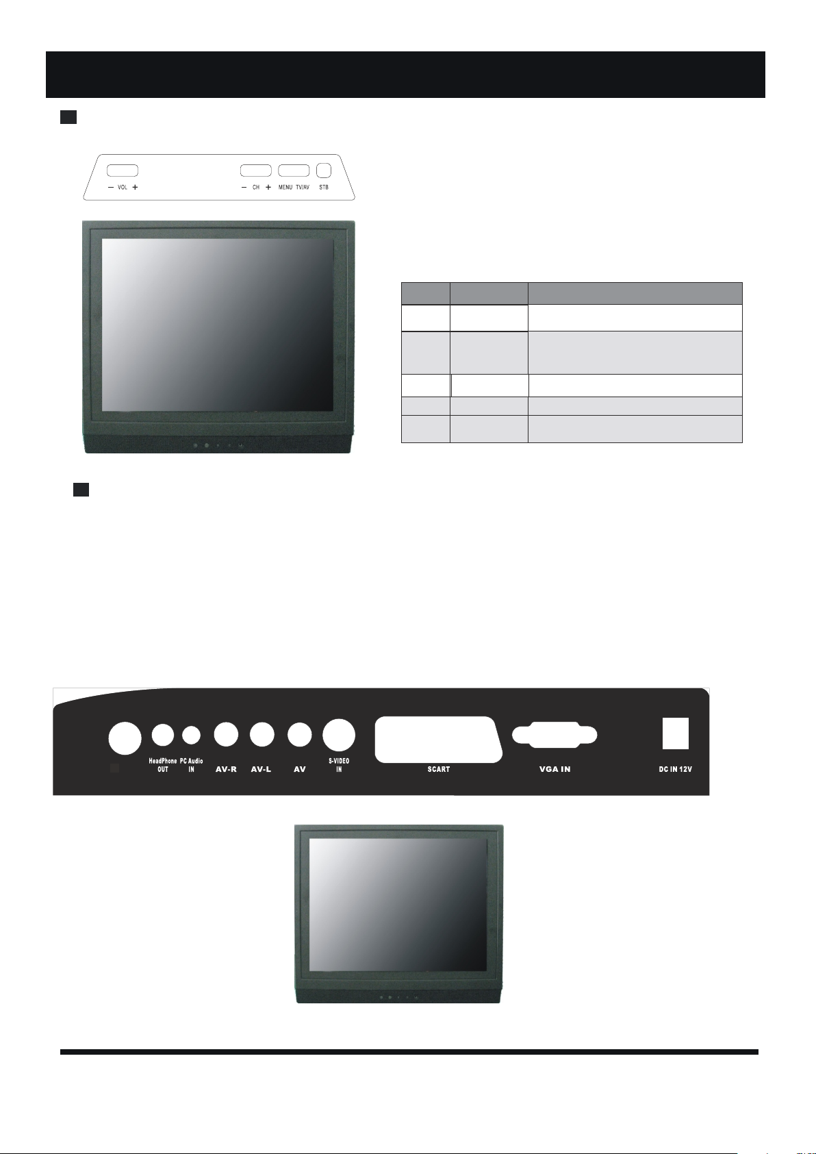
Akai LTA-15S5N1M User manual

LTA-15S5N1M


CONTENTS
CONTENTS
1
18
20
19
21
16
1. --------------------------------OPERATION PARTS 2
2. --------------------SYMPTOMS and CORRECTIONS 5
3. --------------------MANI BOARD FAULT JUDGMENT 6
4. -----------------------------SOFTWARE UPGRADE
5. ---
7.SPECIFICATIONS -----------------------------------
6. -----------------------MAIN ELECTRIC PARTS LIST
8.
SOFTWARE DATA'S RESTORATION AND ADJUSTMENT
ACCESSORIAL CIRCUITR DRAWING and CONFIGURATION DRAWING
--

2
OPERATION PARTS
Top View of TV Set:
1.RF IN
2.HeadPhone OUT
3.PC Audio IN
4.AV-R
5.AV-L
6.AV
7.S-VIDEO IN
1 2 345678910
11
8.SCART
9.VGA IN
10.DC IN 12V
11.HeadPhone OUT(front,W/Volume control)
RF IN
Tips:Headphone(back)and Headphone(front,W/Volume control)use only one.
Rear View of TV Set
ITEM
1
5
2
4
FUNCTION DESCRIPTION
Press to select the input source.
Press to bring up the main menu to the
Press to increase or decrease the
Switch ON the LCD TV when at standby
TV/AV
STANDBY
MENU
3
Press to scan through channels.To scan
Quickly channels,press and hold down
-CH+
-VOLUME+
BUTTON NAME
Screen.
Either +/- button.
sound level.
Mode or vice versa

3
OPERATION PARTS
Remote Control Unit
1.STANDBY
2.AUTO
3.0-9
4.-/--
5.
6.
7.
8.CH+ or CH-+ + --
9.VOL- or VOL+
10.DISPLAY
Press this button to switch on the TV when in standby mode or to enter
standby mode
Press to do auto configuration directly for PC-RGB.
Number selection.
To enter a program number for multipe program channel such as 2-1,etc.
Press to return to the previously viewed program.
Press these buttons to lower or raise the volume.
Press to display program or channel's information.
11.
14.LCD MENU
18.SMODE
17.EXIT
19.MUTE
20.ASPECT
21.NICAM
LCD TV Menu enter/exit.
15.PMODE Press to sycle through the diffrent picture mode.
Press this button to select the desire sound mode.
Exit menu operation.
Mute or restore sound
Press to select Picture Ratio.
UP/DOWN
Press these buttons to select channels in ascending or
descending order.
/
16.INPUT
Press to cycle through the input source to select TV、
AV、S-VIDEO、SCART、PC.
Multi-sound mode selection.
11
18
17
19
20
21
7
2
3
5
4
8
13
14
15
16
6
10
12
1
9
Press to select the favorite channels.
FAV
SLEEP Press to Set the sleeper timer for turning off into standby.
12.ENTER Confirmation key
/
13.LEFT/RIGHT

5
9
6
10
4
7
3
8
2
1
4
TELETEXT OPERATIONS
OPERATION PARTS
1.TEXT
2.HOLD
3.INDEX
4.SIZE
5.REVEAL
6.SUB.PG
7. PAGE UP
9.MIX
8.PAGE DN
10.CANCEL
Hold on or off for current page display.
Request the index page.
Change display size in teletext.
Reveal the teletext information.
Page up.
MIX the teletext and TV picture.
Page down.
Cancel teletext information.
Switch on or off the teletext mode.
Sub page.

5
Please make these simple checks as indicated (●) on the chart for the respective symptoms and their
possible remedies.
No picture, no sound
Poor sound, picture OK
Poor picture, sound OK
Weak picture
Blurred picture
Double image
Lines in picture
Distorted picture
Weak reception on some channels
Horizontal bars
Picture rolls vertically
Poor colour
No colour
Misoperation of Remote control
Remote control unit no operation
On Screen Display Control outside the screen
Symptoms
Possible Remedies
Try different channel, if OK, probably station trouble
Check aerial connections on back of set
Check aerial for broken wires
Re-orient aerial (if indoor type)
Probably local interference, such as an appliance
Adjust fine tuning control
Adjust brightness control
Adjust contrast control
Check if station is broadcasting colour
Adjust colour control
Check if system is correctly set
Check if on/off switch is "on"
Check batteries in remote control unit
SYMPTOMS and CORRECTIONS
SYMPTOMS and CORRECTIONS for TV SET

Power supply trouble
MANI BOARD FAULT JUDGMENT
6
Check F1(F1/3A) for12V
NY
Check if F1、E1are damaged? Turn on th eTV set .
Ch k E9 E10 5VC6 ff
f
3 3V
Y
Check thepowerModule rthe
power net following theF1.
hec 、 、 oo
o
rr
r
.、
E31.8V.
N
Check if the
pin3 ofU7、
U4are 5V? OK
N
Y
U5、
U7 aredamaged.
Check if thepin2 of U2、
U3、
U8is 12V?
YN
1. U2 、
U3、
U8aredamaged.
2.L1
、L11、L3
、
D5、
D6 are
damaged.
Check thecircuitfromthepin2
of U2、
U3、
U8 totheF1.
o
1.

MANI BOARD FAULT JUDGMENT
7
DisplAy(exceptional screen )
Exceptional screen
Check if the cable is correct
and connected tightly
YN
Check if theLCD
panel is OK
p
YN
Change thecable
forpanel
Change LCDso e of U12
Update
2.
3.Display T
T
r
r
ouble
ouble
(white screen)
White screen
Chkif h CN25i12 3
hec the pin 、2、3power
supply is normal?
YN
Check thepower supply Check if th
th
e
e
Voltage is wrong to panal
NY
The panel is damaged Check U12/ 7050 or
update software
circuit

MANI BOARD FAULT JUDGMENT
8
black
Black
screen
N
Y
Check
if
the
pin1
、2
of
CN3
is
12V?
Check
if
the
inverter
board
is
normal
Check
the
12V
power
supply
circuit
N
Change
and
repair
the
Check
if
the
pin3
of
CN3
Y
inverter
board
Check
if
the
pin59
of
the
U12 is 0V?
is
high?
N
V?
Check
the
power
supply
of
U12/7050
or
update
the
software
Check
if
R110、
R46、
Q10
are
damaged
)
een
r
sc
(
ouble
TrayDispl
4.

MANI BOARD FAULT JUDGMENT
9
Audio Trouble
(Nosound)
Nosound
Is there audio input
YN
Check if the setting of volume
and M
UTE are normal
Check ithe pin 4,6 of
NY
f pin
the U15 has output signal
Check ifthe power
U1/TDA1517 – pin7
NY
Y
Check ifthe voltage of
U15‐pin8>8v
Y
Check ifthe pin50、
U12 has signal
signal
output?
YN
N
Check ifD48、
R239、
Q24 are damaged
Check the
Speaker or
the cable
connec with
RESET
Check
peripheral
audio Check
U15
Check ifthe U12 has
di i l i
co t t
panel
driver board
equipment to oU15
au o signalinput?
?
supply of
is12V
NN
51of the
Y
Repairthe
power
circuitfrom the
the U12
i d dsupply for
U15
ris amage
Function Trouble(TV video
)
TVcan’t search any
channel/no picture
Confirm if theRF
cable do have signal
YN
Check if the pin7 of
T1 is 5V?
YN
N
Check if T1 pin4, 5has
data fo I2C
Check the power supply
circui fT1
N
rI C
Check if T1 pin11 have
cito1
Y
N
signal
NY
Check external
Check the I2C circuit
( between T1 pin4 , 5
/Change T1
Check th
ecircuitfrom
T1 t o U14/TDA9885
RFsignal source and U12/SPV7050
pin56,pin57)
TChange The SAW1 or
U14 /TDA9885/9886
5.
6.
-

MANI BOARD FAULT JUDGMENT
10
Function
Trouble
(AV、
S_VEDIO
、
SCART
、
HDMI、VGA)
AV
no
picture
Check
if
the
CN29
have
CVBS
signal?
N
Y
Check
peripheral
video
equipment
N
Y
Check
if
the
pin26
of U12 has signal?
f
?
N
Y
Check
the
circuit
between
th N29and U12
1.Check
the
power
supply
of
the
U12
2 U12 is damaged
the
C
2.
3. Updata
the
software
AV no sound
Check if the CN29 has
audio signal?
N
Y
Check if the pin33、
34 of
th U12 has signal?
N
Check peripheral
audio equipment
Y
e
YN
Refer to“ 5”
1.Check thepower
supply of the U12
2U12 is damaged
.
3. Updata thesoftware
7.

Function t rouble(S_VEDIO)
S_VEDIO no picture S_VEDIO no sound
Check if the CN16
have Y/C signal? Refer to“ 7 ”
Check peripheral video
N
Y
Check if the pin23 24
equipment
、
of U12 has signal?
NY
Check th circuitbetween
1.Check the power
supplyofthe U12 e c
the CN16 and U12
o t
2. U12 is damaged
3. Updata the software
8.
MANI BOARD FAULT JUDGMENT
11

9.
MANI BOARD FAULT JUDGMENT
12
Function trouble
(SCART
)
SCART no picture
SCART
Check
CN1
Check if the pin20 of
CN19 have CVBS signal?
Y
Check peripheral video
N
Y
Check if the pin31、
Check if the pin8、16
Y
equipment
the U12 has signal?
Y
of U12 has voltage?
N
Y
Check peripheral video
1.Check the power
supply of the U12
Refer o“5”
1.Check
supply
equipment
2. U12 is damaged
3. Updata the software
to 2. U12
3. Up
9 has
32
d
o
is
ata
if
f
N
n
th
audio
th
o
damaged
osound
e pin2、
6 of
signal?
N
Check peripheral
video equipment
e power
f th e U12
the software

Function trouble
(VGA
)
VGA no picture
Check if the pin 13 、14 of
CN15 have the signal?
N
YN
Y
Check if the pin1、2、3Check peripheral
of CN15 has signal?
YN
video equipment
Check the circuit
1.Check the power
supply of the U12
between CN15 and U12
2. U12 is damaged
3. Updata the software
10.
11.
MANI BOARD FAULT JUDGMENT
13
Function t rouble
(HDMI )
HDMI no picture/sound
Check if the pin 19 of
CN14 is LOW?
OR PIN15,16 of CN14 has I2C
SIGNAL?
N
YN
Y
Check if the pin10、
12
Check U9 、U1
of CN14 has signal?
NY
Check peripheral
1.Check the power
supply of the U12
video equipment
2. U12 is damaged
3. Updata the software

SOFTWARE UPGRADE
ATV SOFTWARE UPGRADE
1.PC settings
1.1.Please run operation system of windows XP,advice
Using English windows XP.
1.2.Please open the computer's hardware device manager,
Set the Baud Rate of port COM1 and port COM2 to
115200. Please use default setting about other setting
Items.
1.3.Open control panel of windows XP,enter view item
Of folder option,cancel selecting hidden extension of
Known file type.
1.4.Copy 705 IS folder into PC.cancel all " 0 P"
File's attributes of folder.
1.5.Run 705 IS .exe,Press Option and set these item as0 P " " :
14
ISP mode:Safe(Keeps the top 8k)
Packet Size:128
Default baud rate: 115200
And choose Keep transimt baud rate as default
Choose effectual port between COM1 or COM2.
2.2.Connect the upgrade match board to PC by R 232
2.Connection PC and TV
2.1.Disconnection the Power from TV.
Cable,connect the VGA plug on the upgrade match
board to VGA Socket on TV main board.
2.3.Connect DC12V to upgrade match board.but don't
connect the Power to TV now.
S

SOFTWARE UPGRADE
15
Upgrade file.
3.Upgrade
3.1.Press"Select Files",and choose and open the
3.2.Connect DC12V to TV main board.
3.3.Press"Start",then upgrade start.
3.4.Until it display "finished!...",upgrade is finished.
3.5.First disconnection the Power from TV,then pull
out the VGA plug from TV main board.
Warning:Don't disconnection the Power while upgrading!
Note:This software need restoration after upgraded.

ATV
1.OSD RESTORATION
3.SOFTWARE DATA'S ADJUSTMENT
3.2.1.General Setting 1-9:
1.1.Enter LCD TV menu.
1.2.Select Function item.
1.3.Select Reset item,then press ENTER button,OSD will
Restore.
SOFTWARE DATA'S RESTORATION AND ADJUSTMENT
16
2.INNER DATA RESTORATION
2. 1.Press LCD MENU button,then press 1147 numbers,
3. 1.Press LCD MENU button,then press 1147 numbers,
It's into Factory Menu.Press LCD MENU button
2. 2.Select E2PROM Setting item,press RIGHT button
3. 2.Select per item,it's may adjust the inner data.
enter it.
Again can exit Factory menu.
2 . . S elect Factory item,press RIGHT button or 3 Reset
ENTER button,then will restore inner data.

SOFTWARE DATA'S RESTORATION AND ADJUSTMENT
17
3.2.2.ADC Adjust_Picture:
3.2. 3.Decoder Adjust_Picture:

Work if data is error.
Note:Inner data is in effect after exit all menu.if
restore inner data,it get back inner data into
default data,and manual adjustment data isn't
saved.
SOFTWARE DATA'S RESTORATION AND ADJUSTMENT
18
3.2.4.E2PROM Setting,Reset Factory:
3.2. 5.System Config 1-2.
3.2. 6.Chip Debug,Tuner AGC adjust:
3.2. 7.Version Info:
Warning:Don't optionally adjust default data,TV can't
Other Akai LCD TV manuals

Akai
Akai DLC-E2250 User manual

Akai
Akai LCT2785TA User manual

Akai
Akai 42" User manual

Akai
Akai LTC-16RSX2M User manual

Akai
Akai LT-3207AB User manual

Akai
Akai LCT40Z7TA User manual

Akai
Akai LTC-32R5X3HCM User manual

Akai
Akai LTA-16S01P User manual

Akai
Akai LCT42HA36 User manual

Akai
Akai LTA-26C904 User manual

Akai
Akai LCT2660 User manual

Akai
Akai LTC-32R5W4HCP User manual

Akai
Akai LT-32Q5LFH User manual

Akai
Akai LT-2203AB User manual

Akai
Akai LCT42Z7TAP User manual

Akai
Akai LCT3201AD User manual

Akai
Akai LCT2715 User manual

Akai
Akai LCT3226 User manual

Akai
Akai LCT3785TA User manual

Akai
Akai LCT42Z5TA User manual