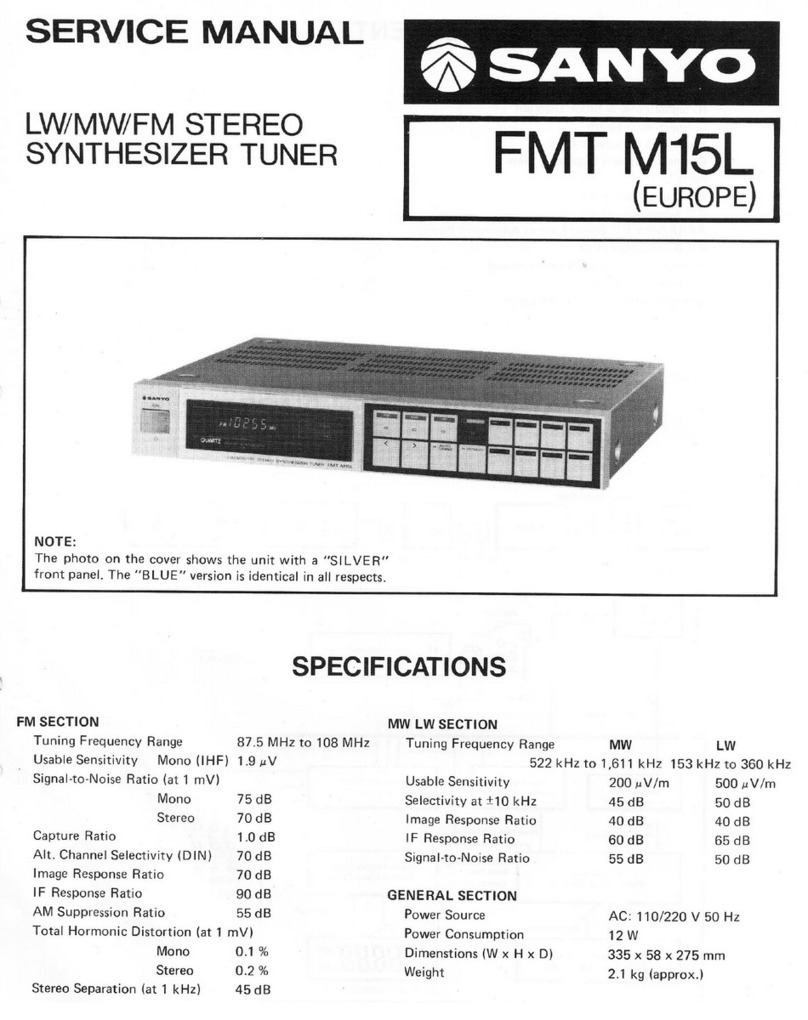
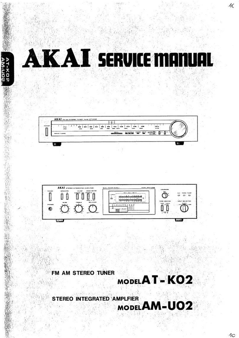
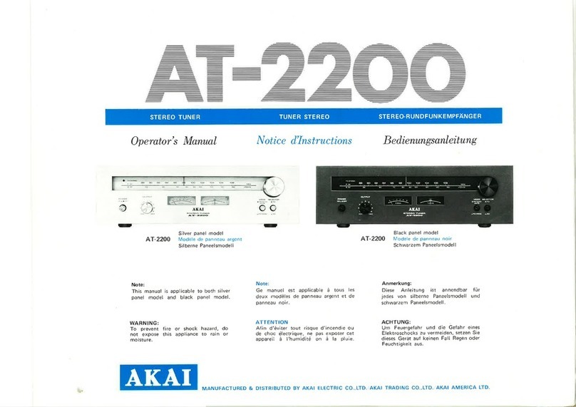
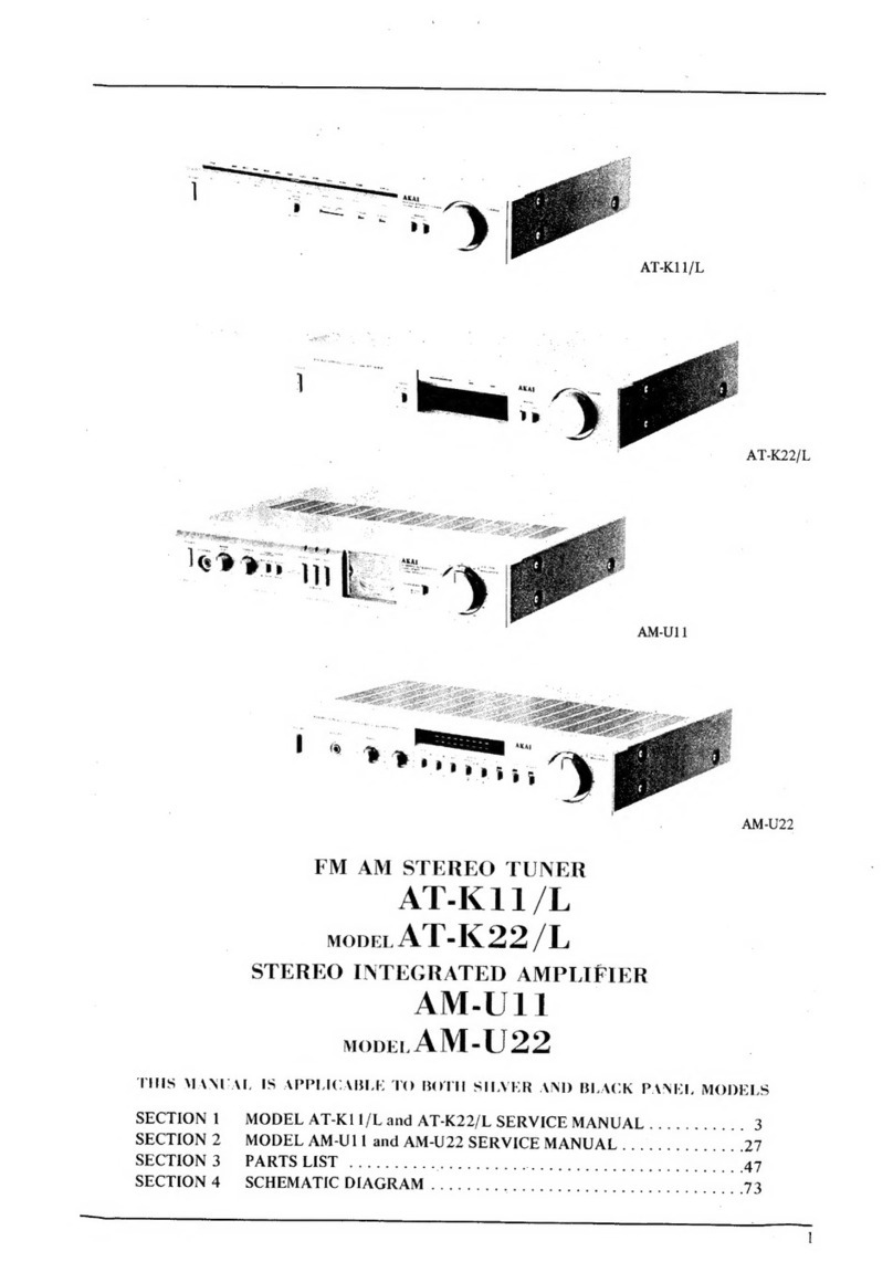
Akai AT-93/L User manual

·
AKAI
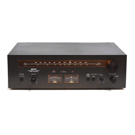
QUARTZ SYNTHESIZER TUNER
AT-93/L

This
is
the
Akai
1
Quartz
Synthesizer
Tuner
Use the Akai
tuner
in combination with the other
components in the Akai
Pro-series
and you will
have
an
excellent hi-fi system.
Features
• Stable accurate reception microcomputer con-
trolled quartz synthesizer tuner
• 20 station random preset system (See page
6)
• Sensitive large
AM
loop antenna (See page
8)
• Computer controlled
FM
anter-ma
selector and 2
separate terminals for dual
FM
antenna connec-
tion
(See
page
8)
•
FM
mute system (See page
5)
•
FM
IF band
select
system
(WidelNarrow, see
page 7)
•
FM
auto mode system (See page
5)
• 6-way tuning system including timer controlled
tuning (See page
6)
• Wide
scale
LED
(Light
Emitting
Diode) signal
strength indicator
• Dual gate MOS (Metal Oxide Semi-conductor)
FET
(Field Effect Transistor) incorporated Front
end
•
Microcomputer
controlled
antenna
switching
system with
PIN
diodes
• Improved PLL (Phase Locked Loop) quartz syn-
thesizertuning system
• Akai original open loop multiplex circuit with
DC
servo
circuit
for
accurate
reproduction of
FM
stereo signals
• Large
capacity
and high stable power supply
system
with
fast
recovery
diodes, low noise
zennerdiodeand high quality parts
• Separate
power
supply
system for digital and
audio sections
• Large FL (Fluorescent) display
• Large pedestals
Table
of
contents
This is the Akai QuartzSynthesizerTuner
.......
1
What you should know to protectyourself
.......
2
Making the right connections
...................
3
Controls
..................................
:.
..
4
Listening to the
radio.
. .. ... . ... .. .. .. ... .. ..
..
5
6-waytuning system
..........................
6
Operation details
...........................
7-8
Antennas
.....................................
9
On
the RESET button
.........................
10
Problem? Let's check
........................
10
Specifications
...............................
11
WARNING
To prevent fire or shock hazard, do not expose this
appliance to rain or moisture.
Power requirements
Power requirements for electrical equipment differ
from area to area. Please ensure that your machine
meets the power requirements
in
your area.
If
in
doubt, consult aqualified electrician.
120
V,
60
Hz
for USA and Canada
220
V,
50
Hz
for Europe except
UK
240
V,
50
Hz
for
UK
and Australia
110-120
V
/220-240
V,
50/60
Hz
convertible for
other countries.
Voltage
conversion
Models for Canada, USA, Europe,
UK
and Australia
are not equipped with this facility. Each machine is
preset at the factory according to its destination,
but some machines can
be
set to 110
V-120
V or
220
V-240
V
as
required.
If your machine's voltage can be converted:
Before connecting the power cord, if the propervol-
tage for your area is not shown, turn the VOLTAGE
SELECTOR located on the rear panel of the ma-
chine with a screwdriver
so
that the correct voltage
is indicated.
i[]l
22Q.240V
110·120V
'--
VOLTAGE
SELECTOR-
Tuning frequency
step/FM
De-emphasis
conversion (Voltage
convertible
models
only)
Set the
tuning
frequency step for your area after
changing the operating voltage.
Set the
AM
FM
STEP/FM DE-EMPHASIS selector
on
the rear panel of the tuner as follows:
For North and South America
Setthe selector to the 10kHz175
J-Ls
position
For Othercountries
Set the selector to the 9 kHz/50
J-Ls
position
After
changingthe position
of
this
selector
Press the RESET button after turning
on
the power.
J
AMSTEP~
101<
9K
100KDsou
FM
STEP/
DE·EMPHASIS

What
you
should
know
to
protect
yourself
Watch out! You
mightget
an
electric
shock.
• Never touch the plug with wet hands.
• Always pull out by the plug and never the cord.
• Only let a
qualified
professional
repair or re-
assemble
the
Akai
tuner.
An
unauthorized
person
might
touch
the internal parts and re-
ceive a serious electric shock.
• Never
allow
a child to put anything, especially
metal, into the Akai tuner.
Let's
protect
the
Akai tunertoo.
• Use only a household
AC
power source. Never
use
a
DC
power source.
• Make sure that the power consumption of each
component does not exceed the wattage speci-
fied
on
the rear panel.
• If water is spilled on the Akai tuner, disconnect
it
and
call yourdealer.
• Make sure that the Akai tuner is well ventilated
and
away from direct sunlight. Be careful not to
block the side ventilatorof the Akai tuner.
•
To
avoid damage to the internal circuits and the
external surface, keep away from heat (stoves,
ete.)
• Avoid using spray type insecticide near the Akai
tuner. It can damage the finish and might ignite
suddenly.
• To avoid damaging the finish, never use dena-
turated alcohol,
paint
thinner
or
other
similar
chemicals to clean the Akai tuner.
• Place the Akai tuner on a flat and solid surface.
•
If
you
don't
plan
to
use
the
Akai
tuner
for
a
long
period
of
time,
disconnect
the
power
cord.
To enjoy the Akai tuner for a long time, please read
this
operator's manual thoroughly.
CAUTION
To prevent
electric
shock,
do not use this
polarized AC
power
plug with
an
extension
cord
receptacle
or
other
outlet
unless
the
blades can be fully inserted to prevent blade
exposure.
2

Making the right connections
3• Turn offall the components before connecting.
• Connectthe power cord last. .
• Make sure that you connect the white P'IN-plugs
to the left (white)
jacks
and the red PIN-plugs to
the right (red) jacks.
•
Connect
everything
securely.
Loose
connec-
tions can cause distortion.
• To
prevent
damage to the cords, connect and
disconnectby holding the plug, not the cord.
FM
(75
n)
A terminal for main
FM
antenna
connection
Holes for attaching
antenna holder Ground terminals for antenna
FM
(75
n)
Bterminal for sub
FM
antenna connection
o --1
[~M--~'
-~
o
AM
LOOP ANT terminals for AM loop antenna
connections
OUTPUT (L/R)
jacks
for amplifier connections Power cord and plug
FM
antenna
'"
'"
[@"@@@;
i~·~~@i
AM
loop antenna
Amplifier
~~t~pJ
I
.[0
o
Tuner
o
OUTPUT
jacks
connection
Connect the Akai tuner's OUTPUT
jacks
and
the amplifier's TUNER
jacks
with the provid-
ed connection cord, (left and right)
T-shape FM antenna
connection
Connect
the provided T-shape
FM
antenna
(using
the
FM
antenna
plug) to the tuner's
FM
(75
n)
A terminal on the rear panel, then
attach the antenna to a wall.
o AM
Loop
antenna
connection
Open both the
AM
LOOP ANT terminal tabs
and insertone wire into each hole.
Close the tabs to complete the connection.
Attach the
AM
loop antenna to the provided
holder or hang it where best reception can be
obtained. Refer to page 8 "How to attach the
AM
loop antenna".
o
After
you have
connected
everything:
Note
Connect the power cord to the
AC
OUTLET of
the Akai amplifier or an audio timer, or
direct-
ly to a household
AC
outlet.
The
provided
FM
antenna is a simple type. If you
want
to
receive
FM
broadcasts
more clearly, we
recommend a higher grade
FM
antenna (multi ele-
mentantenna, etc.) for
FM
reception. See page 9.
INI~()FlTANt.i>.
....)i.
,-~.e.·.ill
.•
~.st.~.~te.clpow.7I
•.
·.Plu9$.·.~n~ibQrdsi~l"~iri~
te~cl~~Jo(1iJ7~~ral
..•
r~f~r~~ct:!;Ih~
pCl''lVf!r])lug
liP
cl··.·.cprdu.~t:!clJnyOl.trCp~Flt
..
yf'l1ar diU.er
from'"
.itheiJlustralfQ~
•••.
lEi<arnPle:.t);
K·,Austra.lla;:
u,S
..
A".Eur()p~!:ltcJ
.

Controls
o
8
8
POWER
button
To turn the power on and off.
ANTENNA
Select
button
To selectthe main or sub
FM
antenna.
IF BAND
Select
button
To
select
the
wide
or
narrow
FM
IF (Inter-
mediate Frequency) band.
BLEND
select
button
To
select
the blend mode during
FM
stereo
reception.
HI-CUT
button
To
turn the high cut filter on or off during re-
ception.
FM
AUTO
button
To set the tuner to the automatic
FM
recep-
tion mode.
LED
(Light
Emitting
Diode)
Indicators
Tells you which mode the tuner is
in.
FL (Fluorescent) Display
Shows tuning information.
LED
Indicators
SIGNAL
Strength
Indicators
. , .
Tells you the strength of the received station s signal.
(;)
0
=~:.=;-:i~
_'""_1-..,·
...
'''"'''-201
/
CD
PRESET SCAN button
To set the tuner to the automatic preset sta-
tion scan mode.
MEMORY
button
To
memorize
preset
stations.
Press
the
button once to memorize preset station num-
bers 1 to 10. Press the button twice to memo-
rize preset station numbers
11
to 20.
PRESET STATION
Buttons
and
Indicators
(1/11
to
10/20)
To
memorize
preset
stations
and
tune
in
.memorized stations.
TUNING
buttons
(UP
>/DOWN
<)
To
tune
in
a station manually.
SCAN MODE Select
button
To
select
the manual
or
automatic
tuning
mode.
BAND Select Button
To
select the band.
MUTING button
To cut inter-station noise during tuning.
HIGH CUT
Indicator
Tells you the high
cut
filter
is
engaged.
I
----------
SIGNAL
I /
2 4 6 B 10
MONO
ANT
B
NARROW
BLEND
2
HI-CUT
ANT
A WIDE;
BLEND
1
ANT A
and
B
Indicators
/
I:
/BLEND 112and MONO
Indicato"
Tells you the blend mode selected.
Tells you which antenna is selected.
NARROW
and
WIDE
Indicators
Tells you which
IF
band of the tuner is selected.
4

Listening
to
the radio
5Basic
tuning
Before proceeding, set your amplifier's inputselec-
tor to the TUNER position.
o
Depress
the
POWER
button
to
turn on the
• Selectthe band with the BAND button.
-===-----8
Tune in a station with the TUNING
UP
> or
DOWN < button.
On
FM
stationtuning (after
setting
the
BAND
to
FM)
To
set
the
tuner
to
the
automatic
FM reception
mode Normally set the tuner to the
FM
AUTO mode with
the
FM
AUTO button. The
FM
AUTO indicator will
light
on
the FL display.
AUTO/MANUAL
i
FM
AUTO
i When set to
the
FM
AUTO mode, the
tuner
auto-
matically
selects STEREO or MONO according to
the station which is tuned in. The STEREO indica-
tor
lights
up
when
a stereo
station
is
tuned
in.
When a monaural signal is tuned
in,
the MONO in-
dicator above the BLEND indicators will light up.
The
ANTENNA
select
button,
IF
BAND
select
button, BLEND select button and the HI-CUT but-
tons
are
set
automatically by the microcomputer.
Pressing
any of these buttons will cancel the
FM
AUTO mode.
Eliminating inter-station noiseduring tuning
MUTING
I I
The FL (Fluorescent)
display
MUTING
Indicator
Tells you the muting system is engaged.
FM
AUTO
indicator
Tells you the tuner is
in
the
FM
auto mode.
Press the MUTING button. The MUTING indicator
will light up and inter-station noise will be eliminat-
ed duringtuning.
• If you want to tune in a weaker station, press the
MUTING
button
once again. The MUTING
in-
dicator will go off and inter-station noise will be
heard during station tuning.
Band
Indicators
SCAN AUTO/MANU
Indicator
Tells you which band is selected. Tells you which tuning mode (manual
or
automatic) the tuner is set at.
:
:.::,~~
TI
AM
MW
I I I I I I I I
1kHz
r---1:STEREO
-r
FM
LW
I U
U.
U U
MHz
LSTEREO
Indicator
TUNED
Indicator
'-----
Frequency/Number
display
Tells you the received station is Tells you a station is tuned in. Shows tuning frequency
in
the stereo mode. (MHz/kHz) and the memorized
PRESET STATION number
(1-10/11-20).

6-wayTuning system
This quartz synthesizer tuner incorporates a 6-way
tuning system.
Before tuning
in
a station
Set
the
amplifier's
input
select
button
to
the
TUNER
position.
Method
* Before tuning in a station manually or automati- 6
cally,
remember
to
select
the
band
with
the
BAND select button.
*
When
using
a preset station button for tuning,
make
sure
that you have already memorized a
station.
Operation
Manual tuning
Set
the
SCAN MODE to MANUAL with the SCAN MODE button,
then repeatedly press the TUNING
UP
> or DOWN < button until
a station is tuned in.
* To
quickly
change the frequency, depress the TUNING button
continuously. For fine tuning press the button repeatedly.
Automatic tuning Set the SCAN MODE to AUTO with the SCAN MODE
button,
then
press the TUNING
UP
<or
DOWN>
button once.
Preset station tuning Press the preset station button once or twice depending on
which
preset station you want to listen
to.
Automatic preset scan tuning
Press
the PRESET SCAN button once. Automatic preset station
scanning
is
engaged.
To
stop
at a preset
station,
press
the
PRESET SCAN
button
again or
press
the PRESET
STATION
button that holdsthe station you want to listen
to.
Manual preset station tuning Repeatedly press the PRESET SCAN button.
Sequential station call tuning with an
Make
sure
you have
tuned
in and memorized a station at the
optional audio timer PRESET STATION number 20 before turning off the power. For
operation details see page
7.
How
to
memorize
a preset station Selectthe band with the BAND button.
AKAI
...
_,
..
,.
__
,_
..."
Notes
•
As
well as memorizing the band and frequency
of a preset station, the tuner's memory system
also
memorizes
the
ANTENNA,
IF
BAND,
HI-CUT and FM AUTO
button's
modes during
preset station memorization.
• If a PRESET STATION
button
is not pressed
within
5 seconds after the MEMORY button is
pressed, the memory operation will be cancelled
automatically.
• If you are using timer controlled preset station
tuning
(Sequential station call function), make
sure
you have memorized the desired stations
at the PRESET STATION numbers 20,
19
and
18 (See page 7).
Tune in a station you want to memorize with
theTUNING
UP
< or
DOWN>
button.
Press the MEMORY button as follows;
Press the button once
.....................
.
To memorize channels 1 to 10. The M in-
dicator
and
1-10
display
will appear on
the
FL
display.
Press the button twice
....................
.
To memorize channels
11
to 20. The M
in-
dicator
and
11-20
display will appear on
the FL display.
Press the button three times
...............
.
To
cancel
the
memory
operation.
The
normal tuning display will appear.
Within
5 seconds
Press the PRESET STATION button where
you want to memorize the station.
When pressing a PRESET STATION button,
it's indicatorwill light up.
After completing a preset station memorization, to
memorize more stations, repeat the above
steps
1
through
4.

Operation
details
7Station interferenceduring
FM
reception
If
interference
from another nearby
FM
station is
botheringthe
FM
station you have tuned in, use the
IF
BAND
select button to reduce the interference.
WIDE/NARROW
I I
NARROW
IF
BAND
WIDE
Press
the
IF
BAND select button until the NARROW
indrcator lights up.
With
the
IF
BAND set to it's narrow setting, interfer-
ence caused by another
FM
station will be reduced.
Normally
set
the
IF
BAND to WIDE for good
FM
stereo station reception. The WIDE indicator will
light
up.
FM
reception enhancement
Use
the BLEND select button to enhance reception
during differentreception conditions.
1/2/MONO
MONO
I I
BLEND
2
BLEND
BLEND
1
Press the BLEND select button as follows;
Normal stereo reception:
Repeatedly press the BLEND button until all the
indicatorsare off.
Noisy stereoreception:
Repeatedly press the BLEND button until the
BLEND 1 or 2 indicator lights up. High frequen-
cy separation and noisewill be decreased.
Weak and noisystereo
reception:
Repeatedly depress the BLEND button until the
MONO indicator lights up. The
FM
mode will be
setat monaural.
Eliminating high frequency noise
(hiss) duringreception
Use the HI-CUT button to eliminate high frequency
signals including noise.
EJ
ON/OFF
I
HI-CUT
I
Press the HI-CUT button. The HI-CUT indicator will
light up.
Note
When the tuner is set at the
FM
AUTO mode with
the
FM
AUTO button
(FM
AUTO will
be
on
the FL
display), using the BLEND or HI-CUT buttons toen-
hance reception is not necessary. The tuner will
adjust
itself
automatically
to the best
FM
tuning
conditions. If these buttons are pressed while the
tuner is set at the
FM
AUTO mode, the
FM
AUTO
mode will be cancelled automatically.
How
to
usethe Sequential station
call function
This tuner has a sequential station call function for
automatic preset station selection. 3 different sta-
tions
can be memorized and then recalled when
the
tuner's
power
is
turned
on with the optional
Akai audio timer. This function can
be
used effec-
tively during absentee recording.
Turn on the power of all the components con-
nected to the optional Akai audio timer.
2 Memorize the stations that you want to record at
PRESET STATION numbers
20,19
and 18.
3 Prepare for sequential station call by pressing
the
10/20
button
of
the
PRESET STATION
button
twice
to tune in the memorized station
number20.
4 Turn off the power with the timer mode button of
the audio timer. Power of all components will
be
turned off and then turned on again at the time
that the Akai audio timer has been programmed
for. (For operation details, please refer to the
audio timer's operator's manual.)
Notes
•
In
order for the sequential function to work prop-
erly, 3 stations must
be
memorized at PRESET
STATION numbers
20,19
and 18.
• During absentee recording, sequential recall of
preset stations begins with the station memo-
rized at
PRESET
STATION number
20
and then
continues with the stations at PRESET STATION
numbers
19
and 18.
• If you are
only
planning to record one station
during absentee recording it is not necessary to
use the sequential station call function. Memo-
rize the station you want to record at one of the
PRESET STATION numbers between 1 and
17
and
use
the last station memory
function
to
recall the station.
• When the power is turned
on
after the third time,
the
tuner
will
automatically
tune
in PRESET
STATION number 18.
Laststation memory
This tuner has built-in last station memory. When
the tuner's power is turned off, the tuning frequen-
cy,
band,
and tuning
mode
of the station at the last
preset
station button you have
pressed
will
be
memorized in the memory system of
the
micro-
computer.
When the power
is
turned
on again
(manually or with
an
audio timer), the tuner is auto-
matically set to that station. This function is useful
if you have a favorite station that you often listen
to,
as itsaves having to tune that station in repeatedly.
This
function can also
be
used to recall a station
during absentee recording.

How
to
attach the AM loop antenna
After
finding
the
best
position
for
reception
by
changing the direction of the
AM
loop antenna and
adjusting it's height:
Attach the provided antenna holder firmly to a
wall, to the rear panel of the audio rack
or
to the
rear panel
of
the
tuner
with
the
two provided
wood
screws.
2
Attach
the
AM
loop
antenna
to
the antenna
holder.
Wall or rear panel
of
the audio rack
AM
loop antenna
oWood screws
How to use the
A/B
FM antenna
terminals
Use the A terminal for the main
FM
antenna con-
nection. For best reception Akai recommends the
use of a higher grade
FM
outdoor antenna for the
main
antenna. Adjust it's direction so that as many
stations as possible can be received.
Use the B terminal for the sub
FM
antenna connec-
tion. Use the sub
FM
antenna to catch stations that
the main antenna can't pick
up
by setting it in a
dif-
ferent position.
Main
FM
antenna
FM(750)A
Sub
FM
antenna
FM
(750)
B
r--·I----ANTENNA-I-----,
FM(
'Sn)
FM(
sn)
AM
mm
A/B
antenna selection
Use the ANTENNA select button to switch between
the A or B antenna terminals when you are using 2
FM
antennas.
ANTA/B
I
ANTENNA
I
Cl
~
Press the ANTENNA select button. The ANT A
or
B
indicatorwill lightup.
How
to use the FM antenna plug
Connect
the
FM
antenna to the A
(750)
terminal
usingthe provided
FM
antenna plug.
Prepare
a
75
ohm
coaxial
cable
(3C-2V
or
5C-2V; not provided) by stripping off approx.
10
mm
of the outer insulation. Be careful not to
cut
through
the
copper
wire
'net' beneath it. Fold
back the copper wire and then strip off about 5
mm
ofthe inner wire's insulating cover. Fig. 1
2 Rotate the
FM
antenna plug and take
it
apart.
Pass
the
prepared
75
ohm
coaxial
cable
through
part
(a)
as shown in Fig.
2,
and then
return
the
copper
wire
to
it's
folded
back
position.
3 Insert the inner wire of the coaxial cable through
the
center
hole of part (b) and stop when the
folded
back copper wire surrounds the bottom
of
part
(b). (If there is a
multiple
core
c~nter
strand,
first
twist
it
together
to form a
single
strand.) Fig. 3
4 Fit parts
(a)
and
(c)
together in the order shown
in Fig. 4 and screw together as shown in Fig. 5.
Fig. 1
Fig.
2 Fig. 3
Outer
cOvering~
m,~2~
mm
~
..
~
Netshield
~
Insulatingcover
(a)
(b)
Fig. 4 Fig. 5
~
..
mt(C)6J
SJ
..
a
(a)
8

Antennas
9
FM
antennas
FM
broadcasts
give you
excellent
sound
quality,
but in
order
to enjoy this
quality,
you
must
catch
the radio waves properly.
Therefore, we recommend
that you selectan antenna
appropriatefor yourarea.
T-shaped
FM
antenna
The
standard
accessory
T-shaped
FM
antenna is
a simple one. Extend the
ends and move it around
to
find
the
best
location,
or
attach
it
to a wall, for
example.
*
Unless
the
radio
waves
are
strong
enough,
the
antenna
can't
deliver
the
full
body
of the music, or
let
the
Akai
Tuner
show itsfull capability.
Multi-element FM
outdoor antenna
Chose
the number of ele-
ments
according
to how
far
you are from the radio
station.
The greater the
number of elements, the
more
signals your anten-
na
will receive and this
in
turn
will improve directivi-
ty
and
lessen
multipath
distortion.
Where to install
the antenna
Keep
the
following
in
mind
when you install the
antenna.
• Make sure that the an-
tenna
is
not
in
the
shadow
of
a
building
and
is
away from car
traffic and high voltage
wires.
• Tune in a station and
move
the
antenna
around until you obtain
the bestreception.
T-shaped
Multi-element
Multipath
distortion
Multipath
distortion
occurs when radio waves
reaching
the
antenna
directly and indirectly (re-
flected
off
buildings,
mountains, etc.) from the
FM
station interfere with
'------------'
each
other.
This
can
result
in
noise and inade-
quate channel separation.
AM loop antennas
This
Akai
tuner
is
equipped with
an
AM
loop
antenna. Attach
this
an-
tenna
to a wall or to the
rear
panel
of
the
audio
rack.
If
good
reception
cannot
be
obtained,
attach a
wire
antenna
of
more
then
5 m
to
the
LOOP
ANT
terminal along
with the
AM
loop antenna.
Grounding
You can
tune
in stations
without grounding, but by
grounding you can effec-
tively reduce noise such
as humming. Also, when
you use
an
outdoor anten-
~---
........
FMl7sn)
. FMI75QI
...
.
na, it helps to prevent
an
'------------'
electric
shock. Connect
one
end
of
the
ground
wire to one of the ground
terminals
(lh)
and the
other
end
to
a
deeply
buried
underground bar
(must
be made of lead).
Do not
connect
to a gas
line, etc. If you live
in
an
apartment that is equip-
ped with a community an-
tenna terminal, grounding
is not necessary.

On
the
RESET
button
When
the tuner does not fuction properly due to in-
terference caused by static electricity, etc., press
the RESET button located
on
the rear panel with
the
blunt end of a pen or pencil, for example. (The
tuner must
be
on.)
Afterwards, the tuner will be set to the following ini-
tial modes:
• Antenna
• IFBAND
• HI-CUT
• MUTING
•
FM
mode
•
SCAN
MODE
• Tuning band
• Tuning frequency
• Memorized preset
stations
A
NARROW
On
On
FM
AUTO
MANU
FM
87.5 MHz
All cancelled
After the
RESET
button has been pressed, it will be
necessary to memorize all broadcast stations once
again.
6
RESET
Problem?
Let's
check
~----------------~10
Onlynoise isheard during AM (MW and LW)
or
FM
reception
The antenna is not properly connected.
For good reception, always connect
an
antenna
appropriate foryour area.
Thefrequency will
not
change when a
PRESET STATION button ispressed
There
is nothing memorized at that PRESET
STATION button.
Memorize astation.
Thestation is
not
received clearly
The
antenna is incorrectly oriented or insuffi-
cientfor good reception.
For good reception, the antenna must be orient-
ed
properly and
be
capable of catching as many
signals as possible.
Sequential station call tuning
will
not
function
properly
The sequential station call function is not en-
gaged.
Set the
10/20
PRESET
STATION button to
20
before turning offthe power.
Make
sure
you have memorized
stations
at
PRESET
STATION buttons 20, 19,and 18.
The presetstation changes automatically
when the
power
isturned on
The SEQUENTIAL STATION CALL function is
engaged.
Press one of the
PRESET
STATION buttons be-
tween 1and 17 before turning off the power.
Tunerdoes
not
function properly
The microcomputer is malfunctioning.
Press the
RESET
button
on
the rear panel of the
tuner.
Should a problem persist, write down the model
and serial numbers and all pertinentdata regarding
warranty coverage
as
well
as
a clear description of
the exisiting trouble. Then contact your nearest
au-
thorized Akai Service Station.

Specifications
11
FM
section
Tuning frequency
range
..............
87.5 MHz to 108.0MHz
Usable sensitivity
.....
1.0
fJ-V
(11.2 dBt)
Quieting sensitivity (SIN =
50
dB)
Mono
..............
2.0
fJ-V
(17.2 dBt)
Stereo
.............
22
fJ-V
(38.2 dBt)
Capture ratio (Wide)
...
1.3 dB
Selectivity
(±400
kHz)
ForWest Germany
Wide
...............
60dB
Narrow
.............
80
dB
Forothercountries
Wide
...............
60dB
Narrow
.............
90
dB
Image
rejection ratio
..
90
dB
IF
rejection ratio
......
100
dB
Spuriousrejection
ratio
...............
100
dB
AM
suppression
ratio.
65
dB
Sub
carrier
suppression ratio
...
70 dB
SIN
For West Germany
Mono
..............
85
dB (at
60
dB~
Stereo
........
,
....
76
dB (at
60
dBJAl
80 dB (at
80
dBJAl
For othercountries
Mono (lHF-A)
.......
90 dB (at
60
dB
JAl
Stereo (lHF-BPF)
...
80
dB (at
60
dBJAl
86 dB (at
80
dBJAl
Distortion (T.H.D., at 1 kHz)
For West Germany
Wide
...............
0.04% (Stereo)
Narrow
.............
0.05% (Mono)1
0.15% (Stereo)
For othercountries
Wide
...............
0.02% (Mono)1
0.07% (Stereo)
Narrow
.............
0.08% (Mono)1
0.3% (Stereo)
Stereo separation
.....
62 dB (Wide)1
(at 1 kHz) 55 dB (Narrow)
Frequency response
..
0
±0.5
dB (30
Hz
to 15 kHz)
AM
section (MW
for
AT
-93L)
Tuning frequency range
For USA and
Canada
............
530
kHz to 1
,610kHz
For othercountries
..
531 kHz to 1,602 kHz
Sensitivity
(Loop
antenna)
.......
300
fJ-Vlm
Selectivity
USA
and Canada
....
50
dB
(±1
0 kHz)
Othercountries
.....
40
dB
(±9
kHz)
Image
rejection ratio
..
40
dB
IF
rejection ratio
......
60
dB
SiN
..................
45dB
Distortion (T.H.D.)
For West Germany
..
0.8%
For othercountries
..
0.6%
LW
section (AT
-93L
only)
Tuning frequency
range
..............
144 kHz to 351 kHz
Sensitivity
............
300
fJ-V
Im
Selectivity
............
55 dB
(±9
kHz)
Image rejection ratio
..
45 dB
IF
rejection ratio
......
37 dB
S/N
..................
40dB
Distortion (T.H.DJ
.....
0.6%
Output level
FM
For West Germany
..
770
mV
(at 100% modulation)
For othercountries
..
770
mV
(at 100% modulation)
AM
................
250mV
(MW for
AT
-93L) (at 30% modulation)
Hi-cutfilter
...........
-6
dB/1
0 kHz
Blend (Separation at 1
kHz)
Blend 1
............
20 dB
Blend 2
............
10dB
Power requirements
...
120
V,
60
Hz
for USA and
Canada
220
V,
50
Hz
for Europe
except UK
240
V,
50
Hz
for UK and
Australia
110-120
V/220-240
V,
50/60Hz
convertible for
othercountries
Dimensions
..........
461
(W)
x87
(H)
x344
(D)
mm
(18.1
x3.4
x 13.5 inches)
Weight
...............
6.3 kg (13.9Ibs)
Standard accessories
Connection cord
......
x 1
FM
di-poleantenna
...
x 1
FM
antenna plug
......
x 1
AM
loop antenna
......
x1
Loop antenna holder
..
x 1
Wood screws
.........
x 2
* For improvement purposes, specifications and
design are subjectto change without notice.
Table of contents
Other Akai Tuner manuals
Popular Tuner manuals by other brands

Monacor
Monacor PA-1200RDSU Installation and operating instructions

Sonelco
Sonelco PCP1272 manual

Sirius Satellite Radio
Sirius Satellite Radio SC-FM1 user guide

Antique Automobile Radio
Antique Automobile Radio 283501B Installation and operating instructions

Kenwood
Kenwood KTC-SR901 - Digital Satellite Tuner instruction manual

Yamaha
Yamaha TX-77 owner's manual