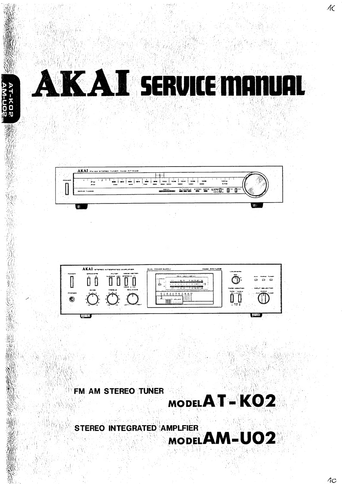
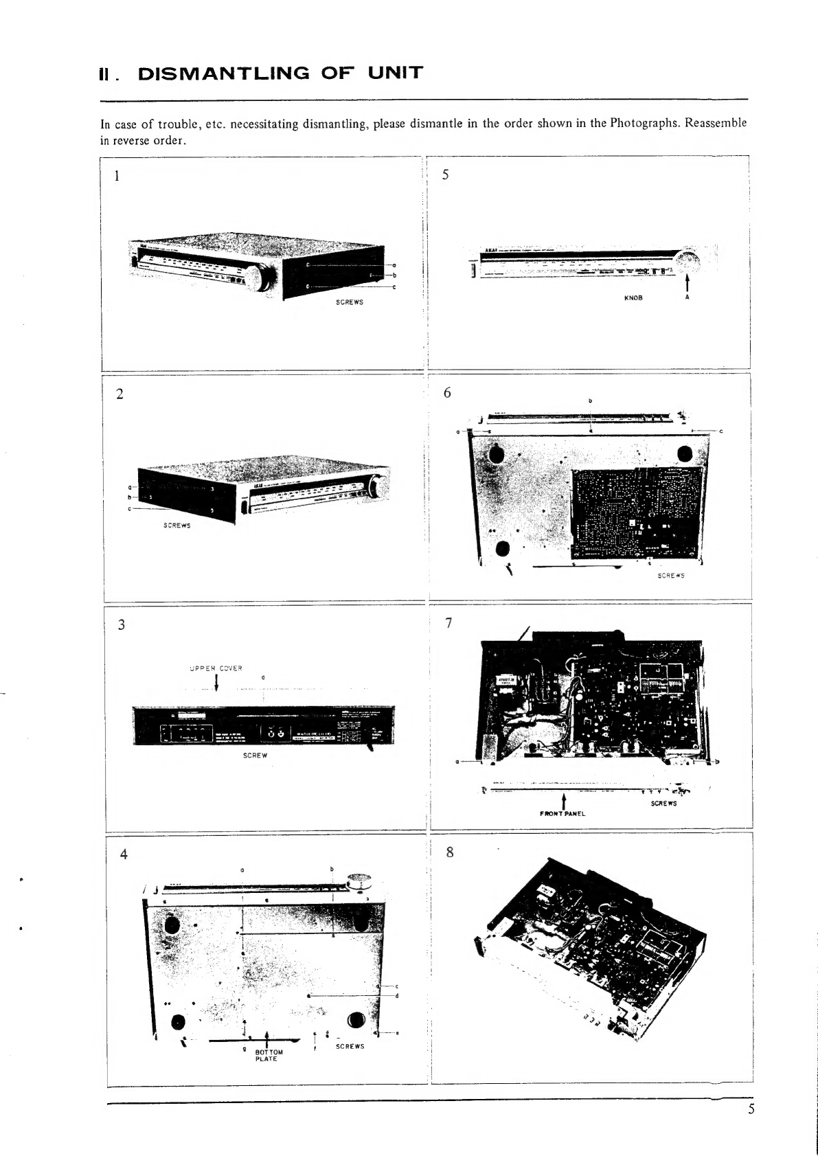
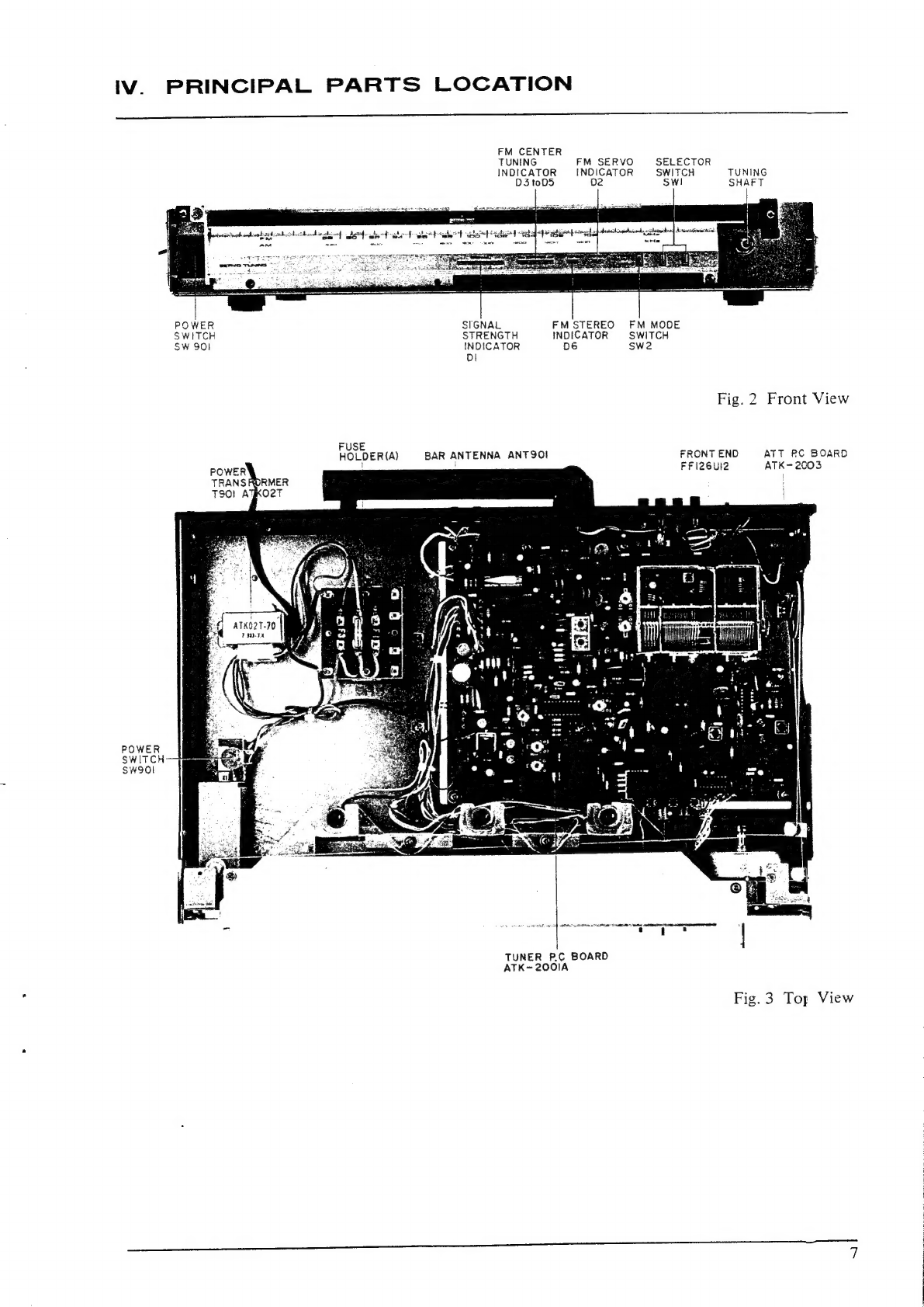
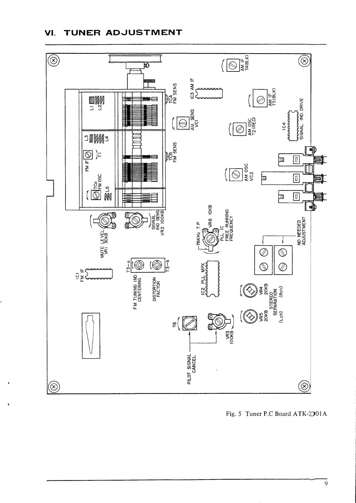
Akai AT-K02 User manual
Other Akai Tuner manuals


Popular Tuner manuals by other brands


NAD
NAD C 445 owner's manual

Sony
Sony ST-SA5ES operating instructions

Pioneer
Pioneer GEX-P700DAB Operation manual

Sirius Satellite Radio
Sirius Satellite Radio SC-FM1 user guide

Antique Automobile Radio
Antique Automobile Radio 283501B Installation and operating instructions

Sanyo
Sanyo FMT M15L Service manual