manuals.online logo
Brands
  1. Home
  2. •
  3. Brands
  4. •
  5. Akai
  6. •
  7. Tuner
  8. •
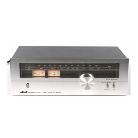
  9. Akai AT-2250 User manual

Akai AT-2250 User manual

{
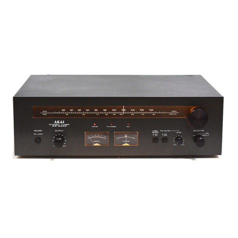
.A'KAI FM aM arEFEô ruñER 'r!,d-r ar-226o
Note: Th¡s manual ¡s also appl¡cable to the black panel model. II
240V, 50 Hz
Operator's Marrunl
E
FM AM STEREO TUNER
WARNING:
* This apparatus must be earthed.
* To prevent fire or shock hazard, do not expose this appliance to rain or moisture.
IMPOBTANT:
The wires in this mains lead are coloured in accordance w¡th the following code:
Green-and-yellow: Earth, Blue: Neutral, Brown: Live
As the colours of the wires in the mains lead of this apparatus may not correspond with the
coloured markings ident¡fy¡ng the terminals in your plug, proceed as follows:
The wire which is coloured green-and-yellow must be connected to the terminal in the plug which
is marked by the letter E or by the safety earth symbol { or coloured green or green-and-yellow.
The wire which is coloured blue must be connected to the terminal which is marked with the letter
N or coloured black. The wire which is coloured brown must be connected to the terminal which
is marked w¡th the letter L or coloured red.
FOR YOUR SAFETY
1. lnsert this plug only into
effectively earthed three-pin
plug-socket outlet.
2. lf any doubt exists regarding
the earthing. consult a quali-
fied electrician.
3. Extension cords, if used,
must be three-core correctly
wired.
^^MANUFACTURED & DISTRIBUTED BY AKAI ELECTRIC CO.,LTD./AKAI TRADING CO.,LTD./AKAI AMERICA LTD.
GOINTFIcILS
ANTENNA INFORMATION
When receiving broadcast signals, the antenna being used is of
great ¡mportance. The pos¡tion of the antenna is especially
important when receiving stereo broadcasts. lncorrect antenna
placement is often the cause of d¡stort¡on or insufficient
channel separation.
* When an FM or AM antenna is placed high in the air,
use a l¡ghtening arrestor to protect the un¡Î.
FM ANTENNA
For FM broadcast recept¡on, the use of a professional type
FM outdoor antenna ¡s most ideal, but when signals are
strong, the standard accessory FM di-pole antenna will suffice.
A variety of antennas are available on the market for use
according to the spec¡f¡c area in which lhey are to be used.
Typical examples are: lndoor Antenna: For about a 20 km
(15 mile) radius from the stat¡on; 3-Element Anlenna: For
about a 60 km (40 mile) radius from the stat¡on; S-Element
Antenna: For about a 80 km (5O milel radius from the
stal ron.
This model is equipped with both 75,Çù and 300o impedance
antenna terminals: 75O Terminals: Use to connect a 75fl
coaxial cable from an outdoor FM antenna placed at a
distance away from the un¡t; 3OOfl Terminals: The supplied
3O0O di-pole antenna is sufficient when the signals are
relatively strong.
* lf in a remote atea, o( inside a concrete bu¡ld¡ng, etc., a
multi-element outdoor antenna is recommended. ln this
case, use 300 ohm terminals.
* When using TV antenna feeder wire, keep in m¡nd that
the w¡re ¡s suscept¡ble to corrosion and lasts only a few
years. Check wire periodically as defective lead-in wire
can cause sound distorl¡on or increased noise.
* A TV/FM Antenna can also be used in place of an FM
antenna.
AM ANTENNA
The AM ferrite bar antenna at the rear of the un¡t ¡s
adequate for normal AM recept¡on. Use AM antenna terminals
when signal strength is insufficient.
FM BROADCAST RECEPTION
Make connections as outlined in CONNECTIONS.
1. Turn on Power Switch.
2. Set Selector to FM posit¡on.
3. Set Mode Switch to FM AUTO/MUTE or FM MONO.
lf the signal strength of the desired stat¡on ¡s weak, FM
MONO posrtion is recommended.
4. Turn Tuning Knob to select desired stat¡on (FM Stereo
Lamp will light to confirm FM stereo recept¡on).
5. Tune until the FM Tuning Meter indicator ¡s at the center
and the S¡gnal Strength Meter reg¡sters as strongly as pos-
sible towards the right of the scale.
6. Adjust controls of the external amplifier.
AM BROADCAST RECEPTION
Make connections as outlined in CONNECTIONS.
1. Turn on Power Sw¡tch.
2. Set Selector to AM position.
3. Turn Tuning Knob 1o select desired station.
4. Ad¡ust AM Bar Antenna as required. Pull out from rear
panel and pos¡t¡on for maximum fidelity.
5. Tune until the Signal Strength Meter registers as strongly
as possible towards the right of the scale.
6. Adiust controls of the external amplif ier.
* As AM broadcasts are in monaural only, position of FM
Mode Switch is irrelevant-
5
6.
7.
8.
I
10
11.
12.
FM DIAL scALE '4r
AM DIAL SCALE
SIGNAL STRENGTH METER
When tuning in FM or AM broadcasts, tune for ìndica-
t¡on as far as possible toward the right end of the scale.
Movement of the needle to left or right indicates signal
st rengt h.
FM CENTER TUNING METER
Turn Tuning Knob to select FM station while observ¡ng
this meter. Tune until the ind¡cator needle comes to
the center of the meter. The Stereo lndicalor Lamp
will light when FM Stereo broadcasts are being received.
FM STEREO LAMP
Lights when FM stereo broadcasts are being received.
TUNING KNOB
Rotate this knob for selection of desired broadcasts.
POWER SWITCH
FM MODE SWITCH
FM AUTO/MUTE: Will automatically receive any FM
broadcasts in stereo or monaural.
* Cuts noise between FM stations
and disturbances from weak inputs.
FM MONO: For listening to FlVl stereo broad-
casts ¡n monaural. Left and right
channels are mixed and em¡tted
from both left and right speakers.
(When FIV broadcast signals are
too weak for stereo separation,
MONO position fac¡litates better
audibility. )
FM/AM SELECTOR SWITCH
Set to FM position to receive FM broadcasts, and to
AM posit¡on for receiving AM broadcasts.
AM FERRITE BAR AN iENNA
Pull out 'rom rear panel for AM reception. lf signals
are not received with sufficient clarity, use an outdoor
antenna and connect to the AM antenna terminal.
FM and AM ANTENNA TERMINALS (See Antenna
lnformation).
OUTPUT JACKS (Left and Right)
Connects to inputs of external amplifier for playback.
COI\INEGTIGINS
Connect to a deeply buried
underground bar.
* Do no1 connect to a gas
l¡ne, etc.
AM Outdoor Antenna 300O parallel FM outdoor antenna or FM
di-pole antenna.
* When using a 75S¿ coaxial cable from
the FM outdoor anlenna. connect to
the 75S¿ antenna terminal, and connect
the shielded ground wire to the ground
terminal.
lf the FM broadcast station is nearby and
d¡stortion exists, use the LOC antenna
term¡nals instead of the DIST terminals of
Model AT-2250 and connect ¡n the same
way as described above.
B Speakers System
AT-2250
1.
2.
3.
4.
sr0ct illm¡-¡¡
lls¡lt lt c¡13 -l¡
/ tÉtúÍtoiGstttill-
NOTES:
1. Avoid us¡ng your tuner ¡n extremely hot or hum¡d places.
2. Heavy noise and poor response of the Tuning Meter
during FM reception may be due to:
A. Antenna oriented in wrong direction; somet¡mes a
gust of wind changes the direct¡on of the antenna.
B. Eroken wiring from antenna to the tuner set. Check
at the output terminal of the antenna and the antenna
term¡nals of the tuner.
* Also check the antenna for proper size from the
geographical point of v¡ew.
3. To prevent ¡amm¡ng in FM reception when cars are rùn-
ning nearby, it may be necessary to ¡nstall the antenna
away from the highway or high in the air. lt ¡s also
advisable, for no¡se suppress¡on, 10 use an exclusive FM
multi-element antenna for strengthening the wave and to
use a 75S¿ coaxial cable in place of TV feeder.
4. lf heavy noise exists during AM recept¡on, re-position the
Bar Antenna. Maximum sens¡t¡v¡ty is obtained when the
Signal Strength Meter ¡nd¡cator reaches the extreme right
end of the scale. ln congested areas of the city or in an
area remote from the stat¡on, connect a vinyl covered
wire to the AM Antenna term¡nals. Hang¡ng the w¡re
out of the window is advisable for better sens¡tiv¡ty.
AM broadcasts are more susceptible than FM to c¡ty
norse,
Be sure not to place the antenna near fluorescent lamps-
5. lf humming ex¡sts during AM recept¡on, re-locate the
tuner- Move the Bar Antenna on the rear panel to f¡nd
a poinl at wh¡ch the humm¡ng is held to a minimum.
After checking for proper connect¡ons and control sett¡ngs.
should . a problem st¡ll ex¡st, write down the model and
serial numbers and all perl¡nent data regard¡ng warranty
coverage as well as a clear description of the existing trouble
and contact your nearest author¡zed Akai Service Station or
the Service Department of Akai Company, Tokyo, Japan.
TECHNICAL DATA
FM TUNER SECTION
Frequency Range - . - . 87.5 MHz to 108 MHz
Sens¡t¡v¡ty (lHF) . . 1.9 ¡¡V
CaptureRatio .....1.3d8
Select¡v¡ty (lHF) . . More than 65 dB
lmage Re¡ect¡on More than 60 dB (98 MHz)
lF Re¡ection More than 85 dB (98 MHz)
Spurious Re¡ection More than 85 dB (98 MHz)
AMSuppression ....60d8
Signalto NoiseRatio . . . . . . . TOdB
Harmonic D¡stortion
MONO . Less than O.IV. (OOy. modulation)
STE REO Less than O.2% llOO% modulation)
Stereo Separat¡on . More than 42 dB (1 kHz)
Sub Carrier Suppression More than 40 dB
Output Voltage . . . . 500 mV (1OO modulation)
Antenna lnput lmpedance . . . . 3OOohmsbalanced/7sohms
u nbalanced
AM TUNER SECTION
Frequency Range . 520 kHz to 1,605 kHz
Sens¡t¡v¡ty {lHF). . . . 100pV/m (Bar Antenna),
17 ¡¿V (External Antenna)
Select¡v¡ty (lHF) . . More than 30 dB
lmage Reject¡on - More than 5O dB (1 MHz)
I F Rejection More than 40 d B
S¡gnal to No¡se Rat¡o More than 55 dB
Output Voltage . 500 mV (30% modulation)
Antenna Bu¡lt-¡n Ferr¡te Bar Antenna
MISCELLANEOUS
Semiconductors Transislors: 6, Diodes: 7, FET: 1,
lCs: 3
Power Requirement. . . - . 24OV,SOHz
D¡mens¡ons ..38O(W) x130(H)x220(D) mm
(15 x 5.1 x 8.7) inches
We¡ght ..4.7k9
(10 3 lbs)
STANDARO ACCESSORIES
FM D¡-pole Antenna . . 1
Connect¡on Cords 1 set
Operator'sManual ....... 1
* For improvement purposes, specif¡cat¡ons and des¡gn are subject
to change w¡thout not¡ce.
MANUFACTURED & DISTRIBUTED BY
AKAI ELECTRIC CO., LTD.
AKAI TRADING CO., LTD.
12-1 4, 2-chome, Hi gashi- Kojiya,
Ohta-ku, Tokyo, Japan
AKAI AMERICA, LTD.
2139 E. Del Amo Blvd., Compton,
Cal¡f., 90220, U.S.A.
TELEPHONE: (213) s37-388O
TELEX:67-7494 Printed in Japan
€)ssoor sor
53061 5 - 05
*4! -
' ,äù
l^
1ù.

Other manuals for AT-2250

1

Other Akai Tuner manuals

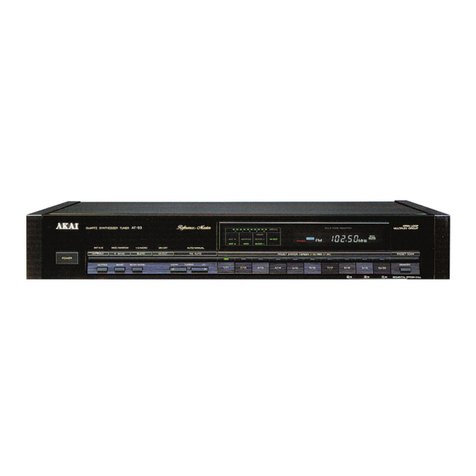
Akai AT-93/L User manual

Akai

Akai AT-93/L User manual

Akai AT-2250 User manual

Akai

Akai AT-2250 User manual

Akai AT-2400 User manual

Akai

Akai AT-2400 User manual

Akai AT-K11/L User manual

Akai

Akai AT-K11/L User manual

Akai AM-U11 User manual

Akai

Akai AM-U11 User manual

Akai AT-K02 User manual

Akai

Akai AT-K02 User manual

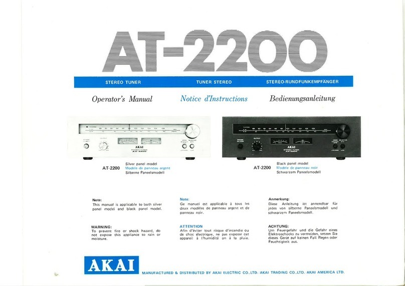
Akai AT-2200 User manual

Akai

Akai AT-2200 User manual

Akai DLC-D1503L User manual

Akai

Akai DLC-D1503L User manual

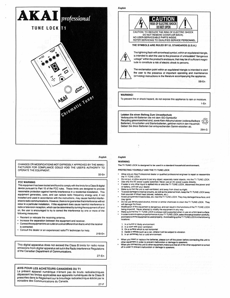
Akai Tune Lock T1 User manual

Akai

Akai Tune Lock T1 User manual

Popular Tuner manuals by other brands

Technics QUARTZ ST-Z400L Service manual

Technics

Technics QUARTZ ST-Z400L Service manual

Parasound Ztuner owner's guide

Parasound

Parasound Ztuner owner's guide

AMC XT Instructions for installation and operation

AMC

AMC XT Instructions for installation and operation

Sony ST-88 Service manual

Sony

Sony ST-88 Service manual

DiabloSport Predator user manual

DiabloSport

DiabloSport Predator user manual

Pioneer GEX-P20HD - HD TUNER FOR READY HEADUNITS owner's manual

Pioneer

Pioneer GEX-P20HD - HD TUNER FOR READY HEADUNITS owner's manual

Pioneer SH-D09 Service manual

Pioneer

Pioneer SH-D09 Service manual

McIntosh MR85 owner's manual

McIntosh

McIntosh MR85 owner's manual

Yamaha T-S500 owner's manual

Yamaha

Yamaha T-S500 owner's manual

TechniSat DIGIPLUS UHD S Quick start manual

TechniSat

TechniSat DIGIPLUS UHD S Quick start manual

Arcam T31 Handbook

Arcam

Arcam T31 Handbook

Freedom9 freeGuard Slim 300 Quick install guide

Freedom9

Freedom9 freeGuard Slim 300 Quick install guide

Sirius Satellite Radio SIR-ALP1 installation guide

Sirius Satellite Radio

Sirius Satellite Radio SIR-ALP1 installation guide

Onkyo T-4555P instruction manual

Onkyo

Onkyo T-4555P instruction manual

Steren 208-900CR instruction manual

Steren

Steren 208-900CR instruction manual

Rotel RT-222 owner's manual

Rotel

Rotel RT-222 owner's manual

Wisi MICRON MyM Pro installation guide

Wisi

Wisi MICRON MyM Pro installation guide

Marantz AV7702 owner's manual

Marantz

Marantz AV7702 owner's manual

manuals.online logo
manuals.online logoBrands
  • About & Mission
  • Contact us
  • Privacy Policy
  • Terms and Conditions

Copyright 2025 Manuals.Online. All Rights Reserved.