3 3
4. The software program is set to compensate for rapidly changing water levels. If the water level in the tank is
rising rapidly due to a high inflow and little or no discharge, the controller anticipates the need to start
closing the valve prematurely and does so to prevent overflow of the tank. In a similar fashion, if the water
level in the tank is falling rapidly due to a high discharge rate, coupled with an insufficient inflow, the
controller will begin to open the valve prematurely in an effort to keep the water level in the tank within the
dead zone.
Switch 6 of the PCB DIP switch selects the controller’s sensitivity to water level changes and affects how item 4 above modifies the basic regulation
algorithm. The High setting for this switch causes the controller to react very quickly to changing water levels. This causes more wear on the valve
components because the valve changes direction most often at this setting.
The Rapid Level Change Compensation controlled by switches 7 and 8 on the PCB DIP switch also affects the
controller’s response to changing water levels. The Rapid Level Change Compensation determines how strongly the basic algorithm is modified once
a changing water level is detected. This setting also affects the wearing of the valve components. The higher the compensation level is set, the more
tightly the water level in the tank is controlled, even with large unequal inflow and discharge rates. However, the cost of this tighter regulation is more
wear on the valve components as the controller continuously adjusts the valve to meet changing conditions within the tank.
The controller has the ability to activate an external no-voltage-input counter using the “closed” micro switch as a trigger. When the “closed” micro
switch is activated, a set of dry relay contacts will close. When the switch is deactivated, the relay contacts open back up. These contacts have no volt-
age on them and are available at the “INPUT SWITCHES AND COUNTER” connector, terminals A and E.
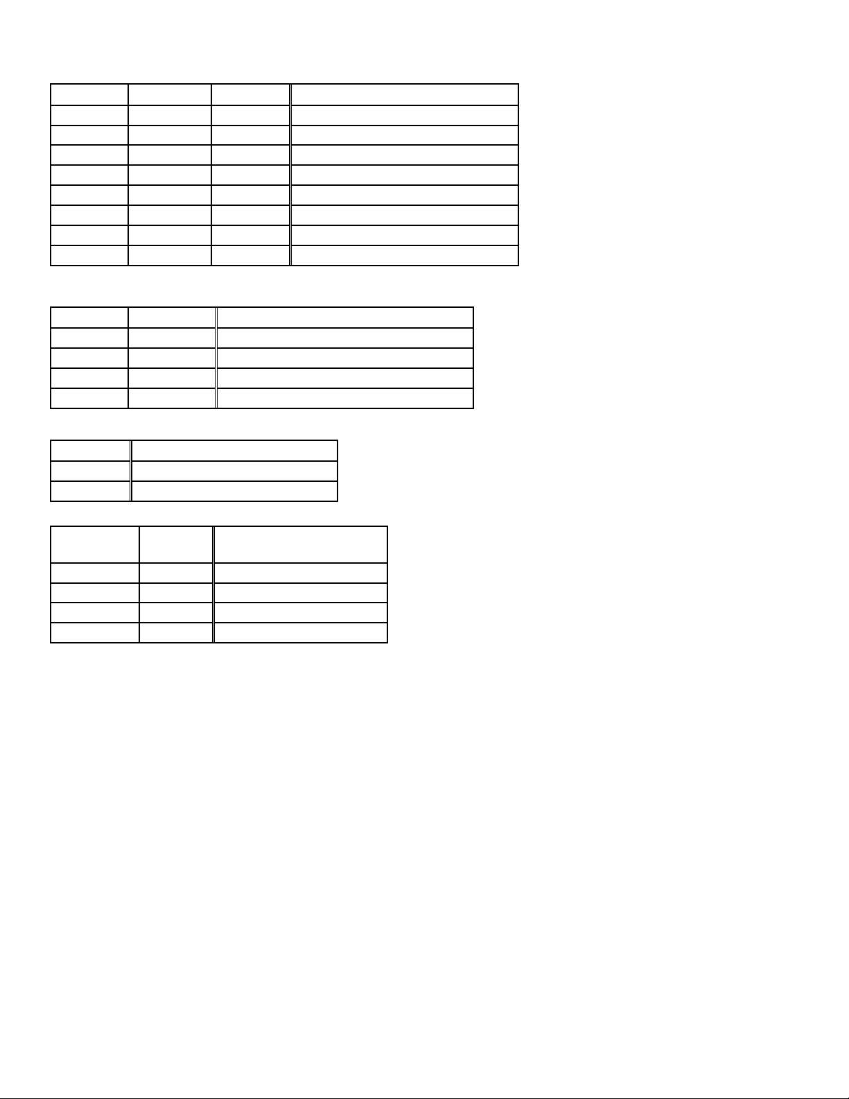
The PCB inside the logic box has a red and a green LED that is used to indicate the various operating conditions of the valve. External LEDs can be
plugged into the logic box at the LEDs connector and will duplicate the function of the
on-board LEDs. The current-limiting resistors are built onto the board so ordinary 2-volt LEDs should be used. The
following table describes the LED behavior during valve operation.
OPERATING INSTRUCTIONS
Please read the following instructions completely before applying power to the Auto Tank Fill System.
1. Make sure all connectors are plugged in and connected properly.
2. Place the Enable/Close switch in the Close position.
3. Apply power to the Auto Tank Fill System.
4. About 1 second after power is applied to the system, the Controller will close the Tank Fill valve. Power
to the valve motor is automatically removed when the valve reaches the closed position. If the valve is
already closed at power up, the controller will detect this condition.
5. If the Tank Fill Valve has responded correctly to item 4 above, move the Enable/Close switch to the
Enable position. This is the position for normal operation of the Auto Tank Fill System. If the tank is
empty, the controller will immediately begin to open the Tank Fill Valve. If the valve is already at the fully
open position, the controller will maintain the valve in that position. If the tank is full of water, the
controller will close the Tank Fill Valve. If the valve is already closed, the controller will maintain the valve
in this position.
TROUBLESHOOTING
The following instructions may prove helpful in troubleshooting the Auto Tank Fill System:
Tank Fill Valve Does Not Operate
1. Make sure power is applied to the Auto Tank Fill System.
2. Place the Enable/Close switch in the closed position for at least 5 seconds.
LED STATUS VALVE OPERATING CONDITION
Solid Red Valve is fully closed against the hard stop
Quickly Blinking Red at 5 times a second Valve is closing
Slowly Blinking Red at once a second Valve is stopped at the micro switch just shy of the closed hard stop
Solid Green Valve is fully open against the hard stop
Quickly Blinking Green at 5 times a second Valve is opening
Slowly Blinking Green at once a second Valve is stopped at the micro switch just shy of the open hard stop
Solid Red and Solid Green Valve is stopped somewhere between the open and closed micro switches
No Red and No Green No power to the logic box