Akron Brass 3406 User manual

STYLE 3406 ELECTRIC RISER
The following is intended to provide the basic instructions for installation, operation and maintenance of the Electric
Riser, and to assist in attaining the best possible performance from the unit. Read and understand these operating
instructions before use.
TOOLS REQUIRED
• UtilityKnife • Mediumatscrewdriver
• MediumPhillipsscrewdriver • Smallatscrewdriver
• SmallPhillipsscrewdriver • 3/4inchhexheadwrench
• Deutschcrimptool(P/NHDT-48-00)
• Electrician’spliers(multipurpose,strippingandcrimping)
PRODUCT RATINGS
MaximumMotorCurrentDraw:
12 volt versions 22 amps
24voltversions 11amps
NormalOperatingCurrent:(Dependingonoperatingconditions–pressure,ow,etc.)
12 volt versions 17 amps
24voltversions 8.5amps
MinimumVoltage:(Truck engine must be operating for proper voltage requirement.)
All12voltmotors:11.5voltswhileoperating
All24voltmotors:23voltswhileoperating
MaximumFlow:1250gpm(4800lpm)
MaximumPressure:250psi(17 bar)
PRODUCT WARNINGS
WARNING: Forreghtinguseonlybytrainedreghters.
WARNING: Chargetheunitslowly.Rapidchargingmaycauseapressuresurgethathasthepotentialtocausean
injury,ordamageriserand/orthemonitor.
WARNING: DONOTstowordeploytheRiser/Monitorwhileowing.Pressingthestowordeploy
buttonscausesthenozzletomoveautomaticallyandthewaterstreammaycausedamagetoequipment
orinjurytopersonnel.
WARNING: Aimtheunitinasafedirectionbeforepumpingwaterthroughit.(e.g.awayfrompowerlines)
WARNING: Althoughthelogiccircuitboardincludesawater-resistantcoating,itisimportanttokeepwateroutof
thecontrolboxandlogicbox.Prolongedexposuretowaterwillcausedamage.Whenthecoverofthe
controlboxorlogicboxisremoved,checkthatthegasketunderthecoverisintactandfreeofdirtand
debris.
WARNING: Donotusetheelectriccontrolswhentheoverridecranksarebeingusedorareinpositionforuse.
WARNING: Maketheconnectionofthevehiclebatterythenalstep.
WARNING: Replacetheidenticationtagsiftheyshouldbecomewornordamaged.
WARNING: DONOTexceedthemaximumpressureorowratingsoftheriser.Exceedingtheseratingsmaylead
toaninjuryormaycausedamagetothemonitor.
WARNING: DONOTinstallshutoffsontheoutletoftheelectricmonitor.Shutoffsincreasethepotential
forpressuresurgesduetowaterhammer,whichhavethepotentialtocauseaninjuryordamagethe
riserand/ormonitor.
WARNING: Risermayextendifwaterpressureisappliedpriortodeployingtheassembly.
121700
!
!
!
!
!
!
!
!
!
!
!

2
WARNING: Ifnotequippedwithanautomaticdrainvalve,draintheRiserafterusetoprevent“freeze
damage”.
MECHANICAL ATTACHMENT OF ELECTRIC RISER TO MONITOR
WARNING: INSUFFICIENTSTRUCTURALSUPPORTCANLEADTOFAILURE,WHICHHASPOTENTIALTOCAUSE
ANINJURY.THEREFORE,ADDITIONALSTRUCTURALSUPPORTATTHEINLETFLANGEORATTHE
INLETELBOWMAYBEREQUIRED.
ThemonitoristobemountedtotheMonitorSupportFlangewithfour5/8”boltsandnutsofgradeve
minimumandsuitablewasherswithaminimumofsixthreadsengagement.Thenotchthatiscutintotheinletangeis
thefrontofthemonitor.Theboltsmustbetightenedinacriss-crosspatternprogressivelyincreasingtighteningtorqueto
amaximumof100lb.ft.dry.(SeeFigure3.)
EXTENSION STOPS
Theextensionstopssettheboundariesfortheheightthattheriserisallowedtotravel.Thesestopsshouldnotbe
removedoradjustedforanyreason.
MECHANICAL ATTACHMENT OF ELECTRIC RISER TO APPARATUS
TheElectricriserisattachedtotheapparatususingfour1/2-13boltsofgradeveorhigher.Thelengthofthebolts
shouldbe2-1/2”plusthethicknessofthemountingsurface.(SeeFigure3.)
MECHANICAL ATTACHMENT OF MINI UNIVERSAL CONTROLLER TO ELECTRIC RISER
Theminiuniversalcontrollermountstotheelectricriserwiththetwo1/4-20x1"capscrewsandwashersprovided.
(SeeFigure3.)
ELECTRICAL INSTALLATION INSTRUCTIONS
DeckMaster with Prox Switches (No Position Feedback & Universal 1 Logic Box)
A. Connect Mini Universal Controller to Universal 1 Logic Box
(1) Determinethelengthofcable(18AWG,6conductor)neededbetweentheMiniUniversalControllerandthe
DeckMasterlogicbox.Addanadditional6”tothemeasuredlength.Installthesuppliedcordgripintothe
DeckMasterlogicbox.Removethecordgripnutandslideontothecable.Removethecordgripbushing
and compression grommet and slide them onto the cable.
(2) Strip6”ofthejacketoffoftheDeckMasterlogicboxsideofthecableandthreadthecablethroughthe
cordgripbodyonthelogicbox.RoutethecabletotheTB3terminalstriparea.Slidethecompression
grommetandbushingintothecordgripbody.Slidethecordgripnutuptothecordgripbodyandtighten
until the cord is secured.
(3) RefertoFigure2fortheelectricalconnectionbetweentheDeckMasterlogicboxandtheMiniUniversal
Controllerconnectors.ThewiringdiagramontheDeckMasterlogicboxlidcanalsobeused
as a reference.
B. Set the Option (DIP) Switches on the Universal 1 circuit board inside the 3440 DeckMaster logic box
(1) Theswitchesarefactorysetat:
(2) Setswitch#4totheUPposition.ThiswillallowtheRiserandtheDeckMastertobeautomaticallycoor-
dinatedduringdeployingandstowing.WARNING: If switch #4 is down and the DEPLOY or STOW
switch is pressed, damage may occur from the monitor hitting an obstacle due to the fact that the
Riser will not extend or retract.
!
!
12345678
UP(ON) • • •
DOWN(OFF) • • • • •
1 2 3 4 5 6 78
UP(ON) • • • •
DOWN(OFF) • • • •

3
DeckMaster with Position Feedback, All StreamMasters (Universal 1 Logic Box)
Note:ThesoftwarefortheDeckMasterwithPositionFeedbackandalloftheStreamMastersdoesnotsupportthe
ElectricRiser.TheElectricRisermustbeusedinstand-alonemodewithitsowndedicated“Extend/Retract”
toggle switch.
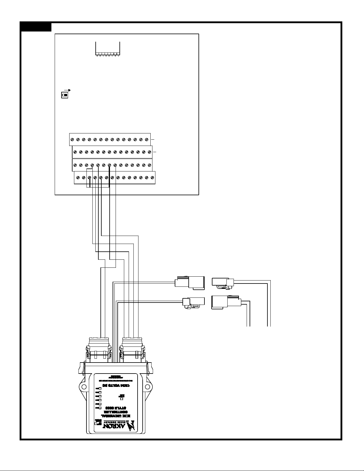
A. Connect an EXTEND/RETRACT toggle switch to the 6033 Mini Universal Controller
(1)UseanSPDTmomentarystyletoggleswitchwherethecenterpositionisoff.
(2)ConnecttheswitchCOMMONterminaltotheblackconnector(righthandsideof6033),positionnumber1.
(3)ConnecttheswitchRETRACTterminaltotheblackconnector,positionnumber2.
(4)ConnecttheswitchEXTENDterminaltotheblackconnector,positionnumber3.
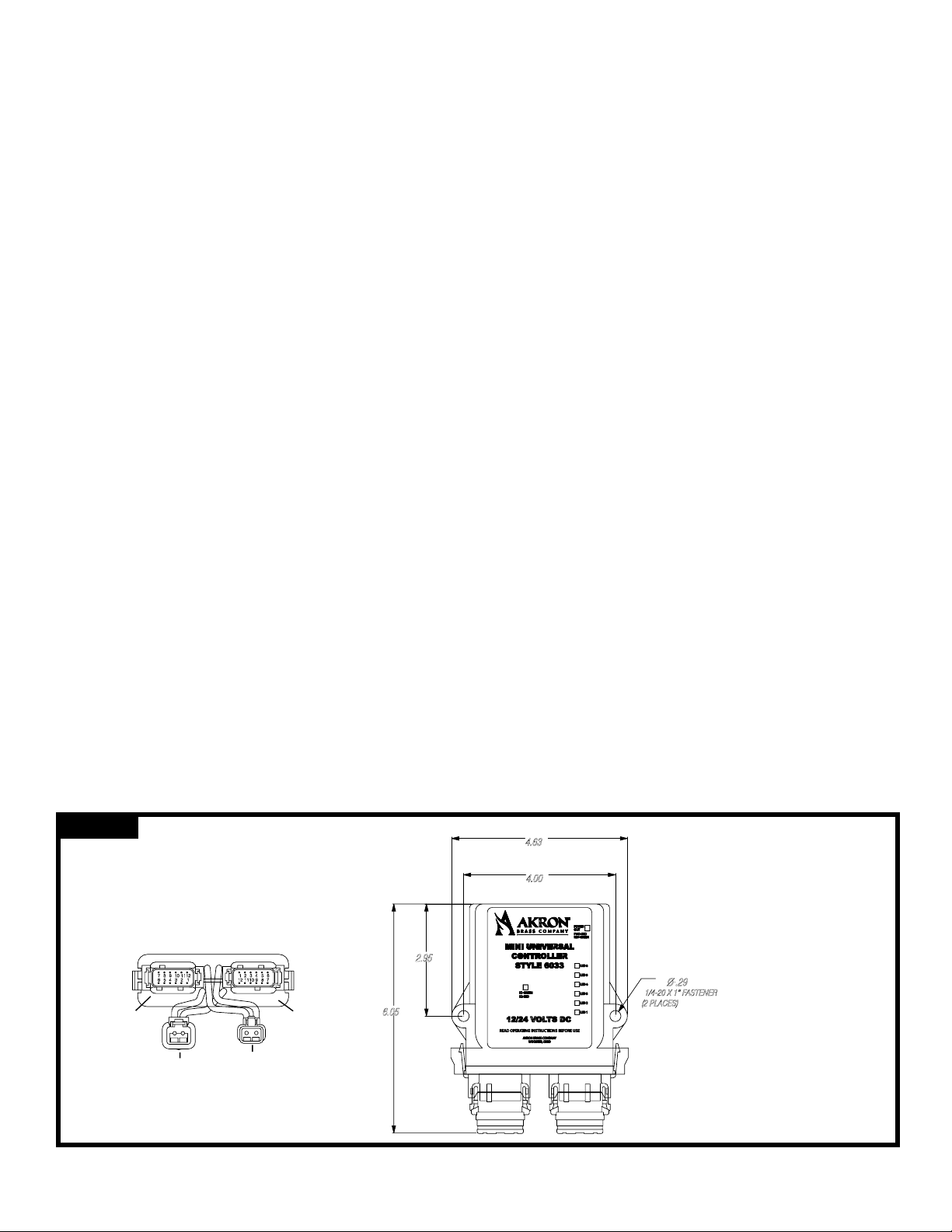
B. Connect power to the DTP04-2P receptacle connector on the 6033 Mini Universal Controller
• 12AWGRedWireis+SystemVoltage(12or24VoltsDC)
• 12AWGBlackWireisSystemGround
• Useappropriatefuseorcircuitbreakertoprotectwiring
• Thevoltageratingonthemotormustmatchthesystemvoltage.
C. Optionally connect the Retracted/Extended Indicator Relays on the 6033 Mini Universal Controller
• FullyRetractedRelay:ThisrelayturnsonwhentheRiserisFULLYRETRACTED.Also,theK1-GREENLED
(Middlefrontof6033)willturnon.Thedryrelaycontactsarelocatedatpositions9and10ofthegray
connector(leftsideof6033),andareratedat1ampmaximum@30VDC.
• FullyExtendedRelay:ThisrelayturnsonwhentheRiserisFULLYEXTENDED.Also,theK2-REDLED(Middle
frontof6033)willturnon.Thedryrelaycontactsarelocatedatpositions11and12ofthegrayconnector(left
sideof6033),andareratedat1ampmaximum@30VDC.
Universal II Logic Box
A. Connect to CAN network using AB cable #721594.
B. Follow the set VP procedure for the monitor that you are using.
C. Enable the Electric Riser in the set-up menu.
• ErrorCode2-1indicatesthattheriserfunctionisenabled,buttheriserisnotavailableonthenetwork.
OPERATING INSTRUCTIONS
WARNING: Be sure to completely deploy the Riser/Monitor before flowing water.
DeckMaster with Prox Switches (No Position Feedback) – “Automatic Mode”
• Deploy:LiftthesafetycoverontheDEPLOY/STOWswitch,pushthetoggleswitchupandthenrelease.The
RiserwillextendtolifttheDeckMasterup12”andthentheDeckMasterwilldeploy.
• Stow:LiftthesafetycoverontheDEPLOY/STOWswitch,pushthetoggleswitchdownandthenrelease.
TheDeckMasterwillstowandthentheRiserwillretract.
• EmergencyStopduringDeployorStow:IfitisnecessarytoimmediatelystoptheRiser/DeckMasterduring
thedeployorstowsequence,activateanyswitchonthecontrolpanelandtheunitwillstopmoving(E-Stop).
Tocompletethedeployorstowsequenceafteranemergencystop,presstheDEPLOYorSTOW
switch again.
DeckMaster with Position Feedback, All StreamMasters – “Stand-Alone Mode”
• Deploy:PressandholdtheEXTENDswitchuntiltheRiserisfullyextended,andthenreleasetheEXTEND
switch.LiftthesafetycoverontheDEPLOY/STOWswitch,pushthetoggleswitchupandthenrelease.The
monitorwilldeploy.
• Stow:LiftthesafetycoverontheDEPLOY/STOWswitch,pushthetoggleswitchdownandthenrelease.
Themonitorwillstow.PressandholdtheRETRACTswitchuntiltheRiserisfullyretracted,andthenrelease
theRETRACTswitch.
• EmergencyStopduringDeployorStow:IfitisnecessarytoimmediatelystoptheMonitorduringthedeploy
orstowsequence,activateanyswitchonthecontrolpanel(exceptEXTEND/RETRACT)andtheunitwillstop
moving(E-Stop).Tocompletethedeployorstowsequenceafteranemergencystop,presstheDEPLOYor
STOWswitchagain.
Manual Override Control: Themanualoverrideistobeused,onlywhenthepowertotheRiserisoff.Toraisethe
Riser,apply50PSIofwaterpressureanditwillgoup.Tolower,turnoffwater,pullthepinatthetopofthe
actuator and lower monitor and riser.
Note: Youwillhavethefullweightoftheriserandmonitor.Itwouldbebesttousemorethanoneperson.
Itwillalsohelptolifetthemonitorandriserasyoupullthepin.

6.05
2.95
4.00
4.63
Ø .29
1/4-20 X 1” FASTENER
(2 PLACES)
123456
7 8 9 10 1112
12 1110 9 8 7
1 2 3 4 5 6
Front
Gray
Power Motor
Black
Figure 1
4
Troubleshooting Tips for the 6033 Mini Universal Controller
(1) Openfusedetection(monitoredcontinuously).
(2) Motordisconnected,oropenmotorcircuitdetection(checkedonceeverytimemotoristurnedon).Wheneither
oftheseconditionsarefound,theMiniUniversalwill:
• Stoptryingtorunthemotor
• TurnoffinputcommandindicatorsLED1orLED6
• TurnOFFRelayK1(GreenLED=Retracted)
• TurnOFFRelayK2(RedLED=Extended)
• TurnonFAULTindicatorLED3
• Remaininthisconditionuntilfaultiscleared/xed,ANDpoweristurnedoff,thenbackon
(3) LED1andLED6areinputsignalcommandindicators.Theyshouldcomeonwhenthe6033MiniUniversal
ControllerisbeingtoldtoExtend,ortoRetract.
(4) The“POWEROUT”LEDatthetoprightsideofthe6033comeson Green when power is being sent out to the
Electric Riser motor to RETRACTthe3406Riser.
(5) The“POWEROUT”LEDatthetoprightsideofthe6033comesonRed when power is being sent out to the
Electric Riser motor to EXTENDthe3406Riser.
MAINTENANCE INSTRUCTIONS
Theelectricrisershouldbeinspectedpriortoandaftereachusetoensureitisingoodoperatingcondition.Periodically,
an unanticipated incident occurs where the unit is used in a manner that is inconsistent with standard operating prac-
tices.Apartiallistoftheseusesincludes:
• Operatingabovethemaximumratedpressureorow.
• Prolongedexposuretotemperaturesabove130°F,orbelow-25°F.
• Operatinginacorrosiveenvironment.
• Havingthemonitornozzlehitaxedobjectduringoperationortransportation.
• Anymisusethatmightbeuniquetoyourspecicenvironment.
Also,therearemany“telltale”signsthatindicaterepairisinorder,suchas:
• Controlsthatareeitherinoperableordifculttooperate.
• Excessivewear
• Poordischargeperformance
• Waterleaks.
Ifanyoftheabovesituationsareencountered,theRiser/Monitormonitorshouldbetakenoutofservice,repaired,and
testedbyaqualiedtechnicianbeforeplacingbackinservice.Greasettingsareprovidedabovetheextensionstops.
Tolubricatetheriser,placeitintheextendedpositionandwipeoffanyoldgreaseresiduefromthetubes.Usinga
manualgreasegun,applytwoshotsofgreasetoeachtting.
MINIUNIVERSALCONTROLLER

5
Figure 2
MASTER
SLAVE
TB1
TB3
1
2
3
4
5
6
7
8
9
10
11
12
13
14
15
16
17
18
19
20
21
22
23
24
25
26
27
28 15
16
17
18
19
20
21
22
23
24
25
26
27
28
1
2
3
4
5
6
7
8
9
10
11
12
13
14
BLACK 12 POSITION CONNECTOR
GRAY 12 POSITION CONNECTOR
2
3
12
11
10
9
Factory Settings
DOWN
DOWN
DOWN
DOWN
Return to Stream During Stow
Jog to Stow or Deploy
Use with Electric Riser
Enable LEARN Mode
UP
UP
DOWN
UP
Enable Timer for Elev. Arm Stow
Stow Nozzle in Cradle
Operate in Stowed Position
Stow Only at HOME Position
FACTORY USE ONLY
RUN MODE
1
8
2
3
4
5
6
7
DTP04-2P
DTP04-2P
DTP06-2S
DTP06-2S
BLUE AND WHITE WIRES
RED AND BLACK WIRES
Notes:
3440 DECKMASTER WITH PROX SWITCHES (NO POSITION FEEDBACK)
- GRAY LOGIC BOX
SEE LID LABEL INSIDE LOGIC BOX FOR ADDITIONAL
1 - DIP Switch 4 must be in the UP position for Electric Riser to operate.
2 - Software version of the 3440 board must be between Version 8 & Version 19.
Older versions (e.g. vers7) will not "tell" Riser to Extend or Retract.
3 - After "LEARNING" new Deploy, or Stow positions, place DIP Switch 8
in the DOWN position. This will lock in the new position.
WIRING INFORMATION
4 - Verify that there is a jumper wire from terminal TB3-3 to TB3-18 and
another one from terminal TB3-3 to TB3-21. The Riser will not operate
if these two jumpers are missing.
6033 Mini Universal
DIP SWITCH FUNCTIONS ARE ACTIVE ONLY WHEN
THE SWITCH IS IN THE UP ("OPEN") POSITION
NOTE:
UP = FUNCTION ACTIVE (SWITCH OPEN)
FROM ELECTRIC
MOTOR ON THE
3406 ELECTRIC RISER
CUSTOMER SUPPLIED
WIRING - POWER FROM
BATTERY
Position 1 = POSITIVE BAT.
Position 2 = NEGATIVE, GND.
1 - RED
2 - BLACK

A
A
30-1/2
8.115 9.000
10.841
7-57/64
13-31/32
6-5/32
4-1/4
6.500 5.500
10.841
4x
n
.531
18-1/2
9-55/64
n
11/16 ON A
n
6.000 B.C.
RISER IN RETRACTED
POSITION RISER IN EXTENDED
POSITION
MINI UNIVERSAL
CONTROLLER
MONITOR
SUPPORT
FLANGE
MINI UNIVERSAL
CONTROLLER
BOLT HOLES FOR
MECHANICAL ATTACHMENT
OF ELECTRICAL RISER
TO APPARATUS
MONITOR SUPPORT FLANGE
MINI UNIVERSAL
CONTROLLER
1/4-20 X 1”
MOUNTING BOLTS
MONITOR OVERRIDE PIN
MONITOR
OVERRIDE
PIN
Figure 2Figure 3
6

NOTES:
________________________________________________________________________
________________________________________________________________________
________________________________________________________________________
________________________________________________________________________
________________________________________________________________________
________________________________________________________________________
________________________________________________________________________
________________________________________________________________________
________________________________________________________________________
________________________________________________________________________
________________________________________________________________________
________________________________________________________________________
________________________________________________________________________
________________________________________________________________________
________________________________________________________________________
________________________________________________________________________
________________________________________________________________________
________________________________________________________________________
________________________________________________________________________
________________________________________________________________________
________________________________________________________________________
________________________________________________________________________
ISO 9001 REGISTERED COMPANY
PHONE: 330.264.5678 or 800.228.1161 I FAX: 330.264.2944 or 800.531.7335 I akronbrass.com
WARRANTY AND DISCLAIMER: We warrant Akron Brass products for a period of five (5) years after purchase against defects in materials or workmanship. Akron Brass will repair or replace product
which fails to satisfy this warranty. Repair or replacement shall be at the discretion of Akron Brass. Products must be promptly returned to Akron Brass for warranty service.
We will not be responsible for: wear and tear; any improper installation, use, maintenance or storage; negligence of the owner or user; repair or modification after delivery; damage; failure to follow
our instructions or recommendations; or anything else beyond our control. WE MAKE NO WARRANTIES, EXPRESS OR IMPLIED, OTHER THAN THOSE INCLUDED IN THIS WARRANTY STATEMENT,
AND WE DISCLAIM ANY IMPLIED WARRANTY OF MERCHANTABILITY OR FITNESS FOR ANY PARTICULAR PURPOSE. Further, we will not be responsible for any consequential, incidental or
indirect damages (including, but not limited to, any loss of profits) from any cause whatsoever. No person has authority to change this warranty.
© Akron Brass Company. 2012 All rights reserved. No portion of this can be reproduced without the express written consent of Akron Brass Company.
rEviSEd: 1/16
Table of contents
Other Akron Brass Firefighting Equipment manuals