Akron Brass Genesis 3590 User manual

1
OWNER’S
MANUAL
For Genesis™ Manual-Hydraulic
Power Unit Style 3590
104656

2
GENESIS™ STYLE 3590 OWNER’S MANUAL
Introduction
The Akron Brass Genesis Style 3590 Manual Hydraulic Power Unit is designed to provide efficient trouble-free operation for many years. This manual
includes all the installation, operating and trouble-shooting instructions normally required to assist in obtaining the best possible performance from this
unit.
DO NOT attempt to install, operate or trouble-shoot this unit without first reading the warnings, installation, operating and trouble-shooting sections of
this manual.
General Product Description
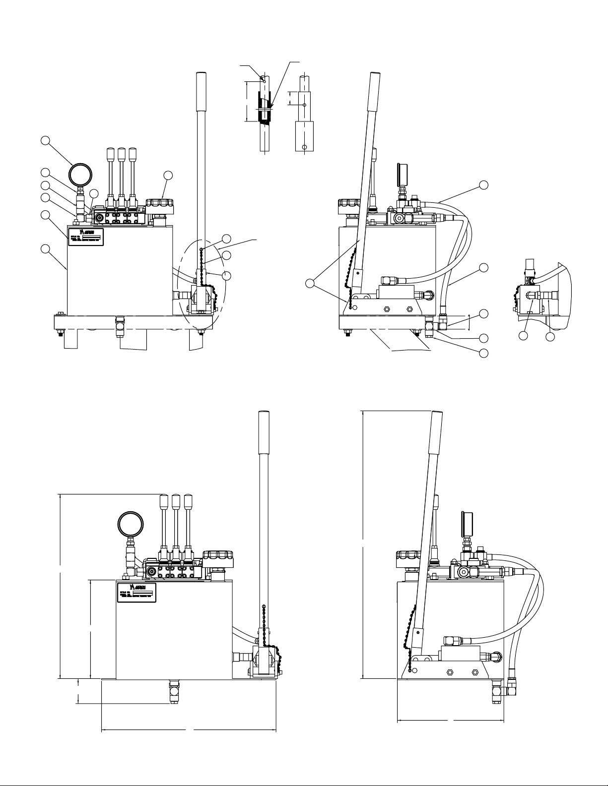
This Genesis Style 3590 Manual-Hydraulic Power Unit provides manual; remote operation of a hydraulically controlled monitor, by means of a manual
hydraulic pump and three function control valves. The unit controls the horizontal, vertical movement of the monitor, plus the pattern of the nozzle. The
speed of each function is directly proportional to the stroke rate of the pump handle. The major components of the Genesis Style 3590 power unit in-
clude a double-acting hydraulic piston pump, a three spool directional control valve with integral pressure relief, and a 5.4 gallon hydraulic fluid reservoir,
all combined into an efficient compact system.
Warning
1. This unit is designed to operate in ambient temperatures of minus 10 degree F (-10 degree F) to plus
140 degree F (140 degree F). DO NOT install this unit in an environment where ambient temperatures of less than
minus 10 degree F (-10 degree F) or more than plus 140 degree F (140 degree F) are possible.
2. This unit is equipped with a fixed (non-adjustable) pressure relief valve, set at 1000 psi. DO NOT attempt to make
adjustments to this valve.
3. Use only the recommended hydraulic fluids listed in this manual. Use of improper hydraulic fluids can result in
poor monitor response especially in cold conditions. Use of improper hydraulic fluids can also result in damage
to internal seals leaving the unit inoperative.
4. This size of the interconnect tubing/hose between the monitor and the power unit is a function of the viscosity
of the selected hydraulic fluid, the ambient temperature, and the distance between the units. If the distance
between the monitor and the power unit is less than 100 feet one way; 1⁄2” diameter tubing is normally sufficient.
Distances beyond 100 feet will require a corresponding increase in tubing diameter. If you have questions
concerning the determination of the optimum tubing size for your installation, contact Akron Brass for
assistance.
Installation And Start-Up
The Akron Brass Manual-Hydraulic Power Unit is delivered preassembled and tested to assure ease of installation and operation. A mounting bracket is
also included which will securely attach the power unit to a 4” to 6” diameter standpipe.
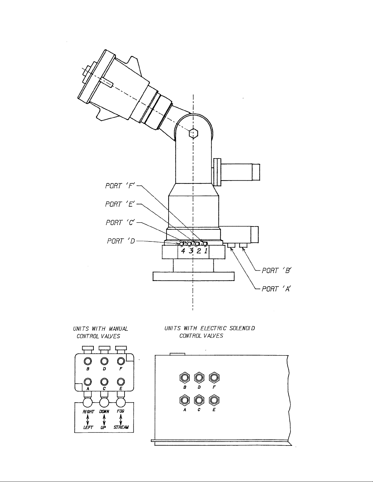
After attaching the mounting bracket to a suitable standpipe, and the power unit to the bracket; as shown in the accompanying installation drawing, the
customer supplied hydraulic interconnect piping which runs between the power unit and the monitor can be installed. Again, referring to the installation
drawing, connect piping between ports as shown (“A” to “A”, “B” to “B” etc.). Ensure that all pipe fittings which terminate at the power unit or monitor are
of the proper type and size (o-ring, NPT etc.).
After the system is installed and piping interconnections are completed the power unit reservoir should be filled to the top with the proper grade of
hydraulic fluid. (See the specifications sections of this manual for recommended hydraulic fluids.)
Prior to placing the unit into operation, all entrapped air must be purged from the system. This can be accomplished by completing each of the following
steps for each of the six hydraulic lines. Remember, purge only one line at a time.
1. Shift the function control lever, located on the valve bank, to the “on” position for the line which is to be purged.
2. Go to the highest hydraulic connection for that line (usually at the monitor) and disconnect it.
3. Using a suitable container to catch oil from the disconnected line, have an assistant pump the hand pump lever
until a solid stream (no air bubbles) of hydraulic fluid is pumped into the can. During this process, have the
assistant monitor the level of the hydraulic fluid in the reservoir. If the fluid level drops below the bottom level of
the sight glass stop and refill the reservoir before continuing.
4. Once a solid stream of oil is observed coming from the disconnected pipe, stop the process, reconnect the pipe
and repeat this procedure with the pipe of the functions opposite member, i.e.; do both pipes for the rotation
function before moving onto the elevation or pattern functions.
5. Repeat steps 1-4 for the remaining two functions.
After the entire purging process is complete, ensure that all connections are tight and leak free. Remove or add hydraulic fluid to reservoir as required to
maintain a level which is approximately 2⁄3 up the sight glass

3
Note:
As a final check, operate each function independently to assure that the actual monitor movement matches the function template mounted on the power
unit.
Operating Principles
Operation is accomplished by shifting one of the control valve levers to the desired operating position as shown on the operating template located on the
top of the power unit, and moving the pump handle in a forward and backward
motion. Only one function should be operated at a time. The speed at which the monitor operates is directly proportional to the stroke rate of the pump
handle. The optimum stroke rate for the pump is approximately 100 to 120 full cycles per minute. When the desired monitor function’s position is
reached, the control valve lever should be returned to the neutral or center position.
Trouble-shooting
Problem Solution
1. Pump handle moves freely but no movement can be accomplished on
any monitor function.
a. Check oil level in reservoir, if ok, go to (b).
b. Air is probably present in the system. Repeat start-up procedure.
c. If problem still exists, check relief valve cavity for foreign material, clean
and reinstall.
d. If problem still exists, disassemble pump and inspect for damaged
seals. Repair or replace as required.
2. One or two functions work fine, but other function does not respond. a. Take lines loose from monitor end of function that does not respond.
Plug them and shift control lever and pump as usual; if system now builds
pressure, the problem is in the drive motor. Inspect and repair or replace
as needed.
Periodic Maintenance
To ensure proper operation, the following perodic maintenance activities should be completed monthly.
Check for proper oil level in the reservoir. Ensure that no water has entered the reservoir.
Operate all three functions (monitor rotation, elevation and nozzle pattern) through their range of motion.
Check hoses and fittings, both on the power unit and monitor for leaks.
To ensure proper operation, the following perodic maintenance activities should be completed annually.
Clean old grease from exposed gears and apply a new layer of Lubri-Plate low temperature grease.
Apply Lubri-Plate low temperature grease to the grease fittings located on the monitor.
Specifications
Pump:
Type — double acting piston pump
Displacement — 1.5 in. 3/full cycle
Stroke rate — 120 full cycles/min = 3⁄4 gpm
Maximum operating pressure — 2000 psi
Handle length — 24”
Handle force — 39 lbs. @ 1000 psi pump pressure
Material — stainless steel and aluminum bronze
Valve:
Type — Directional, double — acting spool type
Spools — 3
Maximum operating pressure — 2000 psi
Relief — 1000 psi fixed (non adjustable)
Material — cast steel

4
Reservoir:
Capacity — 5.4 gallons
Material — stainless steel
General:
Operating temperature — -10 degree F to +140 degree F.
Operating pressure — 1000 psi maximum
Power unit dimensions 20” long X 15” wide X 213⁄8” w/o handle
Mounting bracket dimensions 18” long X 191⁄2” wide X 13” high
Power unit weight — 66 lbs. — without hydraulic fluid
Mounting bracket weight — 40 lbs.
Inter-connect Tubing/Fitting/Fluid Specifications
Interconnect Tubing between the Monitor and HPU:
1/2” OD with a 0.035” minimum wall thickness, per the following specification:
Fully annealed high quality (Type 304 or 316) stainless steel hydraulic tubing ASTM A269 or A213 or equivalent,
seamless or welded and drawn with a hardness of Rb80 or less. Tubing should be without scratches and
suitable for flaring bending.
Hydraulic Monitor Fittings:
Rotation Function:
(2) 9/16”-18 O-Ring, female
Elevation and Nozzle Function:
(4) 1/8” NPT, female
Hydraulic Power Unit Fittings:
All functions:
(6) 1/2” NPT, female
Hydraulic Fluid:
Temperatures from +10° F to +140° F (-12°C to +60°C)- SAE 10W30
Temperatures from +40° F to +140° F (-40°C to +60°C) Amsoil ATF or Dextron III ATF or Equivalent

5
1-1/4
1
2
3
4
17
18
30
31
29
19
5
SEE DETAIL A
21
20
24
23
22
28
26 25
7-1/2
DETAIL "A"
INSTALL ROLL PIN AT ASSEMBLY
AS SHOWN REMOVE FOR SHIPMENT.
REINSTALL AT INSTALLATION
DETAIL "A"
8-32 UNC TAP
THRU ONE SIDE
19-3/
64
10-3/16
18
11
2-9/16
27-43/64
ALL DIMENSIONS ARE APPROXIMAT
E

6
14
15
9
10
6
111278
54
13
16
3X
3X
6X 6X
6

7

ISO 9001 REGISTERED COMPANY
PHONE: 330.264.5678 or 800.228.1161 I FAX: 330.264.2944 or 800.531.7335 I akronbrass.com
WARRANTY AND DISCLAIMER: We warrant Akron Brass products for a period of five (5) years after purchase against defects in materials or workmanship. Akron Brass will repair or replace product
which fails to satisfy this warranty. Repair or replacement shall be at the discretion of Akron Brass. Products must be promptly returned to Akron Brass for warranty service.
We will not be responsible for: wear and tear; any improper installation, use, maintenance or storage; negligence of the owner or user; repair or modification after delivery; damage; failure to follow
our instructions or recommendations; or anything else beyond our control. WE MAKE NO WARRANTIES, EXPRESS OR IMPLIED, OTHER THAN THOSE INCLUDED IN THIS WARRANTY STATEMENT,
AND WE DISCLAIM ANY IMPLIED WARRANTY OF MERCHANTABILITY OR FITNESS FOR ANY PARTICULAR PURPOSE. Further, we will not be responsible for any consequential, incidental or
indirect damages (including, but not limited to, any loss of profits) from any cause whatsoever. No person has authority to change this warranty.
© Akron Brass Company. 2000 All rights reserved. No portion of this can be reproduced without the express written consent of Akron Brass Company.
revised: 4/13
Table of contents
Popular Portable Generator manuals by other brands

Powermate
Powermate PC0401855 instruction manual

National Instruments
National Instruments PXI-5650 CALIBRATION PROCEDURE

EFOY
EFOY ProEnergyCase 2020P user manual

Miller
Miller Subarc DC 650 owner's manual

DEVA Broadcast
DEVA Broadcast DB9000-STC Maintenance and operation instruction manual

BNC
BNC 865B user manual

CIAT
CIAT GGS A050 Ch 45 Installation, Operation, Commissioning, Maintenance

Hyundai
Hyundai HomePower HHD3500 user manual

Magneti Marelli
Magneti Marelli M-MX4000 operating manual

Scheppach
Scheppach SG2500i Translation of original instruction manual

Kohler
Kohler 14RCAL Installation

Absolute Ozone
Absolute Ozone ATLAS Operator's manual