Akron 3462 User manual

TABLE OF CONTENTS
STYLE 3462 FORESTRY BUMPER MONITOR
INSTALLATION, OPERATING AND MAINTENANCE INSTRUCTIONS
PHONE: 800.228.1161 | WEBSITE: www.akronbrass.com
Sheet: 122386
Revision 12/2022
Page: 1 of 17
English ……………………………………………………………...……... 2 - 9
Deutsch …………………………………………………………………. 10 - 17

STYLE 3462 FORESTRY BUMPER MONITOR
INSTALLATION, OPERATING AND MAINTENANCE INSTRUCTIONS
PHONE: 800.228.1161 | WEBSITE: www.akronbrass.com
Sheet: 122386
Revision 12/2022
Page: 2 of 17
The following is intended to provide the basic instructions for installation, operation, and
maintenance. Read and understand these operation instructions before use.
Product Ratings
Maximum motor current draw:
12-volt versions 50 amps each for elevation and rotation motors (Locked rotor current)
3.0 amps for nozzle pattern motor
24-volt versions 25 amps each for elevation and rotation motors (Locked rotor current)
1.5 amps for nozzle pattern motor
Normal operating current (depending on operating conditions – pressure, flow, etc.):
12-volt versions 3 - 10 amps each for elevation and rotation motors
0.7 amps for nozzle pattern motor
24-volt versions 2 - 5 amps each for elevation and rotation motors
0.4 amps for nozzle pattern motor
Minimum Voltage: (Truck engine must be operating for proper voltage requirement.)
All 12-volt motors: 11.5 volts while operating
All 24-volt motors: 23 volts while operating
Mass: 23 lbs. (10.4 kg) without nozzle or quick disconnect base
Maximum Flow: 300 gpm (1135 lpm)
Maximum Pressure: 200 psi (14 bar)
Noise Emission: 94 Db @ 1m with Maximum Flow
Product Warnings
•
Indicates a hazardous situation which, if not avoided, WILL result in death or
serious injury.
•
Indicates a hazardous situation which, if not avoided, COULD result in death or
serious injury.
•
Indicates a potentially hazardous situation which, if not avoided, may result in
minor or moderate injury.
•
Addresses practices not related to personal injury.
For firefighting by trained firefighters only.
The maximum flow of the Bumper Monitor is 300 GPM. The center of the waterway
outlet is 13-3/16" inches from the bottom of the inlet. Ensure these values and an
appropriate safety factor is used to determine a proper support structure.
Aim the Bumper Monitor in a safe direction before pumping water through it.
The Bumper Monitor uses current limiting for both the monitor and nozzle stops. Use
only appropriate Akron Brass nozzles.
Do not use the electric controls when the override cranks are being used or are in position
for use.
If any tags or bands are worn or damaged and cannot be easily read, they should be
replaced.

STYLE 3462 FORESTRY BUMPER MONITOR
INSTALLATION, OPERATING AND MAINTENANCE INSTRUCTIONS
PHONE: 800.228.1161 | WEBSITE: www.akronbrass.com
Sheet: 122386
Revision 12/2022
Page: 3 of 17
Disconnect power and disable flow before maintenance.
Keep all personnel out of the Danger Zone (in front of the outlet of the monitor) when the
water source is attached. Dangerous flow velocities can cause serious injury.
The Bumper Monitor contains moving parts. Keep hands, fingers and objects away from
pinch points.
Not designed for explosive environments.
Exceeding the maximum pressure and flow of the Bumper Monitor or nozzle may cause
damage.
Do not disconnect Bumper Monitor from quick disconnect base while flowing.
Do not use the nozzle as a forcible entry tool.
Drain the monitor and nozzle after each use to prevent “freeze damage”.
Do not install shutoffs on the outlet of the Bumper Monitor.
Use of hearing protection is recommended while operating.
Not recommended for use in saltwater applications.
For use with water or standard firefighting foams only. After use with foam, flush with fresh
water.
The Bumper Monitor, nozzle, logic box, control boxes and field adjustable rotation stops are
made for optimal performance. Do not alter in any manner.
Your Bumper Monitor and nozzle should be inspected prior and after each use, to ensure it is
in good operating condition. Periodically, an unanticipated incident may occur where the
Bumper Monitor is used in a manner that is inconsistent with standard operating practices and
those listed in IFSTA. A partial list of potential misuses follows:
•Operating above the maximum rated pressure and flow.
•Not draining and allowing water to freeze inside the nozzle.
•Dropping the nozzle from a height where damage is incurred.
•Prolonged exposure to temperatures above +130° F, or below -25° F.
•Operating in a corrosive environment.
•Other misuse that might be unique to your specific firefighting environment.
There are many “tell-tale” signs that indicate repair is in order such as:
•Controls that are either inoperable or difficult to operate.
•Excessive wear.
•Poor discharge performance.
•Water leaks.
If any of the above situations are encountered, the Bumper Monitor should be taken out of
service and repaired, plus tested by qualified technicians, prior to placing it back in service.
General Instructions
Review the instructions, wiring diagram, component layout and rotational stops diagram before installing this unit. This unit
operates on 12 or 24 volt DC depending on the unit chosen. All electrical current flows through the wires. The Bumper
Monitor does not act as a ground.

STYLE 3462 FORESTRY BUMPER MONITOR
INSTALLATION, OPERATING AND MAINTENANCE INSTRUCTIONS
PHONE: 800.228.1161 | WEBSITE: www.akronbrass.com
Sheet: 122386
Revision 12/2022
Page: 4 of 17
Electrical Installation Instructions
A. JOYSTICK AND VALVE ATTACHMENT
The following steps will prepare the joystick and valve for attachment to control the harness.
STEP 1 Plug Power and Valve Harness (part #721564 Figure 4) into Control harness power/valve connector
on the monitor (Figure 2).
STEP 2 Plug either end of the CAN Communications Harness (part #721565 Figure 4) into Control box
CAN connector located on the monitor (Figure 2).
STEP 3 Plug the remaining end of the CAN Communications Harness (part #721565) into the CAN
Joystick.
STEP 4 Plug the mating end of the Valve Harness (part #721290) into the Power and Valve Harness (part
#721564) valve connector located at the vehicle end of the harness.
STEP 5 Plug the remaining end of the Valve Harness (part #721290) into the Valve Actuator Motor
connector.
STEP 6 Recognizing that as the monitor moves in the rotation axis, the three cables move with it. You must
allow sufficient free length of the cables before affixing to a stationary point. Assure that the cables
experience no sharp bends throughout the rotation range of travel.
B. BATTERY ATTACHMENT
The Battery connection should be the last connection made.
Connect the flying leads at the end of the Power and Valve Harness (part #721564) opposite the monitor to a
switched battery power source. The black lead should connect to the battery negative, and the red lead to battery
positive. Use butt splices or other appropriate method of choice.
C. MECHANICAL MONITOR ATTACHMENT
The Bumper Monitor is to be mounted on the waterway with a 2” NPT thread. The front of the monitor is identified
in Figure 2. The 2” NPT inlet will have the Quick Disconnect Latch Pin Hole facing to the right when looking
towards the vehicle.
FIGURE 1
Side View
Top View

STYLE 3462 FORESTRY BUMPER MONITOR
INSTALLATION, OPERATING AND MAINTENANCE INSTRUCTIONS
PHONE: 800.228.1161 | WEBSITE: www.akronbrass.com
Sheet: 122386
Revision 12/2022
Page: 5 of 17
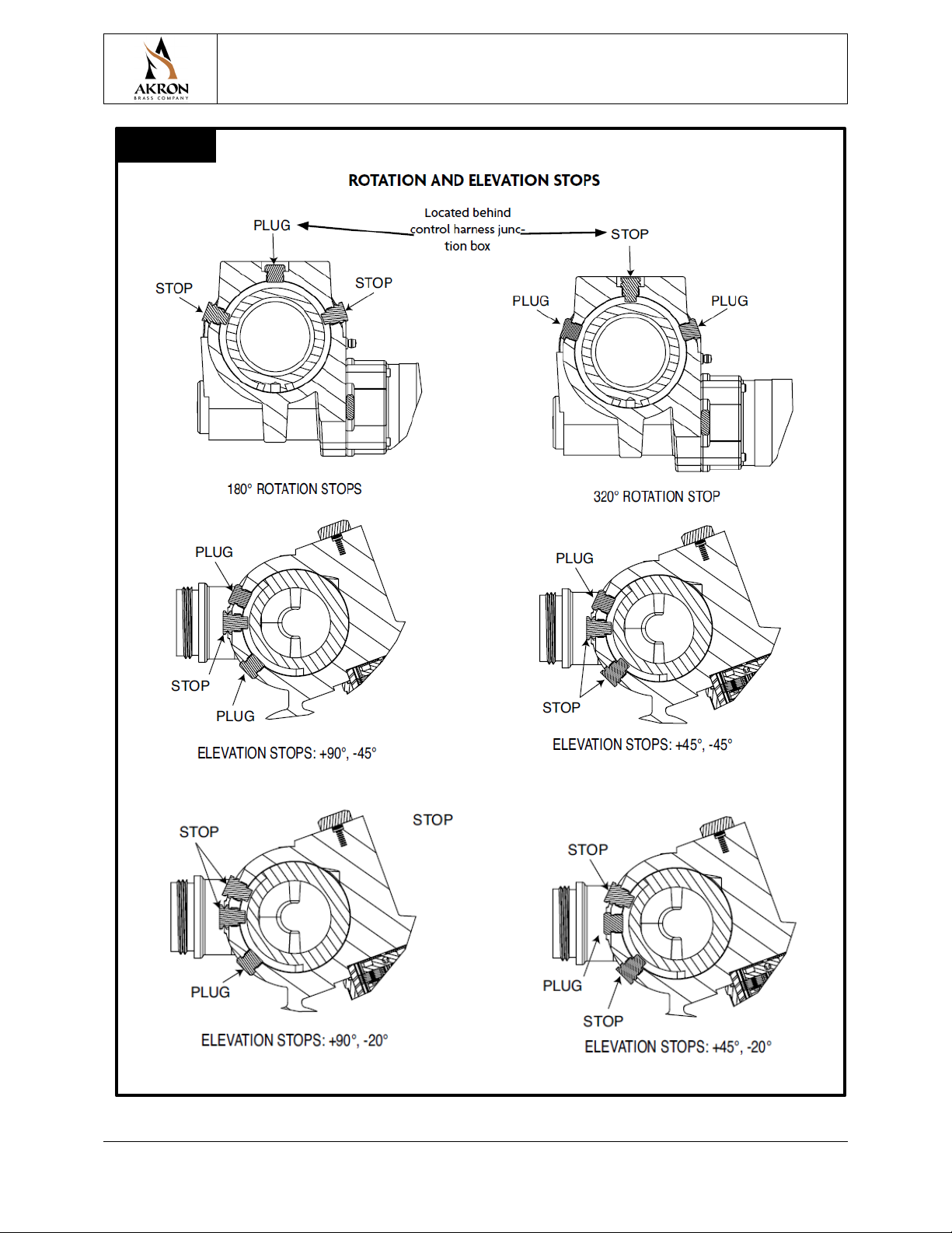
D. THE ROTATIONAL AND ELEVATION STOPS SET THE BOUNDARIES FOR THE AREA IN WHICH THE
BUMPER IS ALLOWED TO TRAVEL. The monitor is shipped with rotation stops at 90˚ right, and at 90˚ left. All
other positions are achieved by switching the factory set stop and the plug in the desired stop location. Both the
stops and the plugs have a 1/2 inch hex head. Refer to Figure 2 and 3 to determine which stop location is needed for
the desired rotation. The elevation stop sets the upper limit of the elevation. The monitor is shipped with elevation
stops at 90° above horizontal and 45˚ below horizontal to meet NFPA. All other vertical positions are achieved by
switching plugs and stops to the desired locations as indicated in Figures 2 and 3. Additional stops and plugs are
provided in the instruction kit for all possible elevation and rotation positions.
Operating Instructions
A. Joystick with Trigger FOR VALVE
To change the nozzle pattern toward the straight stream or fog press the corresponding button on top of the
Joystick. To change the horizontal position right or left move the Joystick towards the appropriate direction.
To change the vertical position up or down move the Joystick forward for down and backwards for up. To
open and close the valve, press the trigger to open the valve and release the trigger to close the valve. The
valve can be maintained open by quickly pressing the trigger twice. Press the trigger and release once to
close the valve.
B. Quick Disconnect
The Bumper Monitor is designed for an optional quick disconnect inlet. If equipped with a quick disconnect
inlet, first mount the inlet on the 2” NPT piping. Make sure the latch pin on the inlet is facing towards the
right (see Figure 2). Place the monitor into the inlet so the two guide pins line up with the groove. Slide the
monitor all the way in and rotate 15° clockwise until the latch pin locks in place. To remove the monitor,
pull the latch pin, rotate the monitor 15° counterclockwise, and lift the monitor out of the inlet.
Make sure the monitor is locked in place before flowing water. The latch pin must be
flush with the housing. (See warning tag on the quick disconnect inlet for further
information.
C. MANUAL OVERRIDE CONTROLS
THE MANUAL OVERRIDE CONTROL IS TO BE USED WHEN THE POWER TO THE MONITOR IS
OFF. A 1/4 inch Allen wrench will actuate the overrides. An override crank is included on the monitor. See
Figure 2 for location of crank. To use the manual override insert the hex head end of the override crank in
the hexagon shaped hole. Then rotate or spin the override crank either clockwise or counterclockwise to aim
the monitor in the desired direction.
WHEN THE OVERRIDE CRANKS ARE NO LONGER IN USE PUT THEM BACK IN THE STORAGE
POSITION.
DO NOT USE THE ELECTRIC CONTROLS WHEN THE OVERRIDE CRANK IS
BEING USED OR IS IN POSITION FOR USE.
Motor Replacement
To replace either the horizontal or vertical rotational motors:
1. Disconnect Power from the unit.
2. Loosen and remove the four socket screws (Item 49 on the Parts List) from the gearbox housing (19).
3. Slowly remove the motor assembly (15) and gearbox housing (19) from the unit.
IMPORTANT: Make sure the internal gear, (Item 25 on the Parts List), remains in place, (hold with a
screwdriver), to avoid gear alignment problems.
4. Loosen and remove the four socket head cap screws (21) from the inside of the gearbox housing that hold the
housing and the motor assembly together.

STYLE 3462 FORESTRY BUMPER MONITOR
INSTALLATION, OPERATING AND MAINTENANCE INSTRUCTIONS
PHONE: 800.228.1161 | WEBSITE: www.akronbrass.com
Sheet: 122386
Revision 12/2022
Page: 6 of 17
5. Remove gearbox housing (19) from the motor assembly (15).
6. Replace o-ring seal (18) on the gearbox housing (19).
7. Attach the new motor assembly (15) to the gearbox housing (19) making sure all four screws (21) are tight.
8. Install the motor and the gearbox housing assembly to the unit making sure all four socket screws (49) are tight. It
may be necessary to rotate the motor slightly to get the motor gear to line up with the gears inside the gearbox.
9. Restore power to the unit.
10. Test the operation of the unit.
Call Akron Brass Customer Service Department if any problems are encountered.
Symptom Potential Cause What to Check Solution
Lack of Power
Remove the Power/Valve Cable connector from
the control box mounted on the side of the
monitor/turret. Check for voltage approximately
equal to vehicle battery voltage between pins 1
(Pos.) and 2 (Neg.) of the cable’s connector.
If no measurable voltage is present, insure proper
DC power is applied to pins 1 and 2.
Remove the CAN Cable connector from the
control box mounted on the side of the
monitor/turret. Check for voltage approximately
equal to vehicle battery voltage between pins 1
(Pos.) and 2 (Neg.) of the control box connector.
If no measurable voltage is present, return the
Control Box/Harness for replacement.
Insert an empty USB Flash Drive (with a status
LED) into the USB connector. Check for lighting of
the Flash Drive status LED.
If the Flash Drive status LED does not light, return
the Control Box/Harness for replacement.
If no status LED’s are lit, check CAN cable continuity
end to end (1 to 1, 2 to 2, etc.), and retest.
If only Power status LED is lit, return the Joystick for
replacement.
If only Power and Transmit LED’s are lit, return the
Control Box/Harness for replacement.
Check status LED’s located near the Joystick
connector for power and CAN activity.
No CAN Communication
Damaged Control Box
Totally Inoperative
TABLE 1

STYLE 3462 FORESTRY BUMPER MONITOR
INSTALLATION, OPERATING AND MAINTENANCE INSTRUCTIONS
PHONE: 800.228.1161 | WEBSITE: www.akronbrass.com
Sheet: 122386
Revision 12/2022
Page: 7 of 17
FIGURE 2

STYLE 3462 FORESTRY BUMPER MONITOR
INSTALLATION, OPERATING AND MAINTENANCE INSTRUCTIONS
PHONE: 800.228.1161 | WEBSITE: www.akronbrass.com
Sheet: 122386
Revision 12/2022
Page: 8 of 17
FIGURE 3

STYLE 3462 FORESTRY BUMPER MONITOR
INSTALLATION, OPERATING AND MAINTENANCE INSTRUCTIONS
PHONE: 800.228.1161 | WEBSITE: www.akronbrass.com
Sheet: 122386
Revision 12/2022
Page: 9 of 17
WARRANTY AND DISCLAIMER: We warrant Akron Brass products for a period of five (5) years after purchase against defects in materials or workmanship. Akron Brass will repair or replace product
which fails to satisfy this warranty. Repair or replacement shall be at the discretion of Akron Brass. Products must be promptly returned to Akron Brass for warranty service. We will not be
responsible for: wear and tear; any improper installation, use, maintenance, or storage; negligence of the owner or user; repair or modification after delivery; failure to follow our instructions or
recommendations; or anything else beyond our control. WE MAKE NO WARRANTIES, EXPRESS OR IMPLIED, OTHER THAN THOSE INCLUDED IN THIS WARRANTY STATEMENT, AND WE DISCLAIM ANY
IMPLIED WARRANTY OF MERCHANTABILITY OR FITNESS FOR ANY PARTICULAR PURPOSE. Further, we will not be responsible for any consequential, incidental, or indirect damages (including, but not
limited to, any loss of profits) from any cause whatsoever. No person has authority to change this warranty. Unless otherwise provided herein. Akron Brass industrial electronic components & the
Severe-Duty Monitor have a one (1) year warranty. Select Akron Brass handline nozzles and valves carry a ten (10) year warranty. Weldon products have a two (2) year warranty from date of
manufacture (excluding consumable components). Select Weldon LED products carry a five (5) year warranty. Honda products have the manufacturers’ warranty and Akron Brass disclaims any
warranty in respect of those products.
FIGURE 4

FORST- UND WALDBRAND-FRONTWASSERWERFER, MODELL 3462
INSTALLATIONS-, BETRIEBS- und WARTUNGSANLEITUNG
TELEFON: 800.228.1161 | WEBSEITE: www.akronbrass.com
Blatt: 122386
Letzte Überarbeitung 12/2022
Seite: 10 of 17
Das Folgende soll die grundlegenden Anweisungen für Installation, Betrieb und Wartung
geben. Lesen und verstehen Sie diese Bedienungsanleitung vor Gebrauch.
LEISTUNGMERKMALE DES PRODUKTS
Maximale Stromaufnahme des Antriebs:
12-Volt Versionen Jeweils 50 A für Antriebe für vertikales und horizontales Schwenken (Anzugsstrom)
3,0 A für Antrieb für Strahlrohrmuster
24-Volt Versionen Jeweils 25 A für Antriebe für vertikales und horizontales Schwenken (Anzugsstrom)
1,5 A für Antrieb für Strahlrohrmuster
Normaler Betriebsstrom (den Betriebsbedingungen entsprechend – Druck, Durchfluss usw.):
12-Volt-Versionen Jeweils 3 - 10 A für Antriebe für vertikales und horizontales Schwenken
0,7 A für Antrieb für Strahlrohrmuster
24-Volt-Versionen Jeweils 2 - 5 A für für vertikales und horizontales Schwenken
0,4 A für Antrieb für Strahlrohrmuster
Mindestspannung: (Der Motor des Nutzfahrzeugs muss sich für den richtigen Spannungsbedarf im Betrieb befinden.)
Sämtliche 12-Volt-Antriebe: 11,5 V während des Betriebs
Sämtliche 24-Volt-Antriebe: 23 V während des Betriebs
Gewicht: 10,4 kg (23 lbs) ohne Strahlrohr oder Notentriegelungsbasis
Maximaler Durchfluss: 1135 l/min (300 G/min)
Maximaler Betriebsdruck: 14 bar (200 psi)
Geräuschbildung: 94 dB bei 1m bei maximaler Durchflussleistung
PRODUKTWARNUNGEN
•
Weist auf eine gefährliche Situation hin, die, wenn sie nicht vermieden wird,
zum Tod oder zu schweren Verletzungen führen wird.
•
Weist auf eine gefährliche Situation hin, die, wenn sie nicht vermieden wird,
zum Tod oder zu schweren Verletzungen führen KÖNNTE.
•Weist auf eine möglicherweise gefährliche Situation hin, die, wenn sie nicht
vermieden wird, zu leichten oder mittelschweren Verletzungen führen kann.
•
Behandelt Praktiken, die nicht mit Personenschäden zusammenhängen.
Nur zur Brandbekämpfung durch ausgebildete Feuerwehrleute.
Der maximale Durchfluss des Bumper Monitors beträgt 300 GPM. Die Mitte des
Wasserstraßenauslasses befindet sich 13-3/16 Zoll von der Unterseite des Einlasses.
Stellen Sie sicher, dass diese Werte und ein angemessener Sicherheitsfaktor verwendet
werden, um eine geeignete Stützstruktur zu bestimmen.
Den Frontwasserwerfer in eine sichere Richtung zielen, bevor Wasser hindurchgepumpt
wird.
Der Frontwasserwerfer verwendet für die Sicherheitssperrfunktion von Wasserwerfer und
Strahlrohr eine Strombegrenzung an. Ausschließlich geeignete Strahlrohre von Akron
Brass verwenden.
Die elektrische Steuerung nicht verwenden, wenn die Übersteuerungshandräder
verwendet werden oder sich diese zu deren Einsatz in Position befinden.

FORST- UND WALDBRAND-FRONTWASSERWERFER, MODELL 3462
INSTALLATIONS-, BETRIEBS- und WARTUNGSANLEITUNG
TELEFON: 800.228.1161 | WEBSEITE: www.akronbrass.com
Blatt: 118746
Letzte Überarbeitung 12/2022
Seite: 11 of 17
Falls irgendwelche Markierungen oder Warnhinweise abgenutzt oder beschädigt und
somit nur schwer abzulesen sind, sollten diese ausgetauscht werden.
Vor der Wartung vom Strom trennen und Durchfluss deaktivieren.
Sämtliches Personal aus dem Gefahrenbereich (vor der Auslassöffnung des Wasserwerfers)
fernhalten, wenn eine Wasserquelle angeschlossen ist. Gefährliche Fließgeschwindigkeiten
können zu schweren Verletzungen führen.
Der Frontwasserwerfer enthält bewegliche Teile. Hände, Finger und Objekte von möglichen
Einklemmpunkten fernhalten.
Nicht für den Einsatz in explosionsgefährdeten Umgebung entwickelt.
Werden Maximaldruck und maximale Durchflussleistung des Frontwasserwerfers oder des
Strahlrohrs überschritten, kann dies Schäden verursachen.
Den Frontwasserwerfer nicht von der Notentriegelungsbasis trennen, während der Durchfluss
aktiviert ist.
Verwenden Sie die Düse nicht als Werkzeug zum gewaltsamen Eindringen.
Entleeren Sie Monitor und Düse nach jedem Gebrauch, um „Frostschäden“ zu vermeiden.
Installieren Sie keine Absperrungen am Ausgang des Bumper Monitors.
Das Tragen eines Gehörschutzes während des Betriebs wird empfohlen.
Nicht für den Einsatz in Salzwasseranwendungen empfohlen.
Nur zur Verwendung mit Wasser oder Standard-Feuerlöschschäumen. Nach Gebrauch mit
Schaum mit Süßwasser spülen.
Der Stoßfängermonitor, die Düse, die Logikbox, die Steuerboxen und die vor Ort
einstellbaren Drehstopps sind für eine optimale Leistung ausgelegt. Verändern Sie in keiner
Weise.
Ihre Düse sollte vor und nach jedem Gebrauch überprüft werden, um sicherzustellen, dass sie
in gutem Betriebszustand ist. In regelmäßigen Abständen kann ein unvorhergesehener Vorfall
auftreten, wenn die Düse auf eine Weise verwendet wird, die nicht den standardmäßigen
Betriebspraktiken und den in IFSTA aufgeführten entspricht. Es folgt eine unvollständige
Liste möglicher Fehlanwendungen:
•Betrieb oberhalb des maximalen Nenndrucks und Durchflusses.
•Kein Ablassen und gefrierendes Wasser in der Düse.
•Fallenlassen der Düse aus einer Höhe, in der Schäden entstehen.
•Längere Einwirkung von Temperaturen über +54 °C oder unter -32 °C.
•Betrieb in einer korrosiven Umgebung.
•Anderer Missbrauch, der möglicherweise nur in Ihrer speziellen
Brandbekämpfungsumgebung auftritt.
Es gibt viele „verräterische“ Zeichen, die darauf hinweisen, dass eine Düsenreparatur
angebracht ist, wie z:
•Bedienelemente, die entweder nicht oder nur schwer zu bedienen sind.
•Übermäßige Abnutzung.

FORST- UND WALDBRAND-FRONTWASSERWERFER, MODELL 3462
INSTALLATIONS-, BETRIEBS- und WARTUNGSANLEITUNG
TELEFON: 800.228.1161 | WEBSEITE: www.akronbrass.com
Blatt: 118746
Letzte Überarbeitung 12/2022
Seite: 12 of 17
•Schlechte Entladungsleistung.
•Wasser läuft aus.
Wenn eine der oben genannten Situationen auftritt, sollte die Düse außer Betrieb genommen
und repariert sowie von qualifizierten Düsentechnikern getestet werden, bevor sie wieder in
Betrieb genommen wird.
ALLGEMEINE ANWEISUNGEN
Lesen Sie die Anweisungen, den Schaltplan, das Komponentenlayout und das Diagramm der Drehstopps, bevor Sie dieses
Gerät installieren. Dieses Gerät arbeitet je nach gewähltem Gerät mit 12 oder 24 Volt Gleichstrom. Der gesamte elektrische
Strom fließt durch die Drähte. Der Stoßstangenmonitor fungiert nicht als Masse.
ANLEITUNG FÜR DIE ELEKTRISCHE INSTALLATION
A. ANBRINGEN VON JOYSTICK UND VENTIL
Anhand der folgenden Schritte können Joystick und Ventil für deren Befestigung am Kabelstrang der Steuerung
vorbereitet werden.
SCHRITT 1 Den Strom- und Ventilkabelstrang (Teilenr. 721564; Abbildung 4) mit dem
Steuerkabelstranganschluss für Strom/Ventil am Wasserwerfer verbinden (Abbildung 2).
SCHRITT 2 Ein Ende des Kabelstrangs für die CAN-Kommunikation (Teilenr. 721565; Abbildung 4) mit dem
CAN-Anschluss am Steuerkasten am Wasserwerfer verbinden (Abbildung 2).
SCHRITT 3 Das andere Ende des Kabelstrangs für die CAN-Kommunikation (Teilenr. 721565) mit dem CAN-
Joystick verbinden.
SCHRITT 4 Das passende Ende eines Ventilkabelstrangs (Teilenr. 721290) mit dem Ventilanschluss für Strom-
und Ventilkabelstrang (Teilenr. 721564) am Fahrzeugende des Kabelstrangs verbinden.
SCHRITT 5 Das andere Ende eines Ventilkabelstrangs (Teilenr. 721290) mit dem Anschluss des
Ventilstellantriebs verbinden.
SCHRITT 6 Wenn der Wasserwerfer mit der Drehachse schwenkt, bewegen sich die drei Kabel mit. Darauf
achten, dass die Kabellänge ausreichend Bewegungsspielraum bietet, bevor der stationäre Einbau
erfolgt. Sicherstellen, dass die Kabel über den gesamten Schwenkbereich hinweg nicht scharf
abgeknickt werden.
ABBILDUNG 1
Seitenansicht
Draufsicht

FORST- UND WALDBRAND-FRONTWASSERWERFER, MODELL 3462
INSTALLATIONS-, BETRIEBS- und WARTUNGSANLEITUNG
TELEFON: 800.228.1161 | WEBSEITE: www.akronbrass.com
Blatt: 118746
Letzte Überarbeitung 12/2022
Seite: 13 of 17
B. ANBRINGEN DER BATTERIE
Der Anschluss der Batterie sollte als Letztes erfolgen.
Die dem Wasserwerfer gegenüberliegenden freien Anschlusskabel am Ende des Strom- und Ventilkabelbaums
(Teilenr. 721564) mit einer geschalteten Batterie-Stromquelle verbinden. Das schwarze Kabel muss mit dem
Negativpol der Batterie, das rote Kabel mit dem Positivpol verbunden werden. Dazu Kontaktverbindungen oder eine
andere geeignete Methode wählen.
C. ANBRINGEN DES MECHANISCHEN WASSERWERFERS
Der Frontwasserwerfer muss mit einem NPT-Gewinde von 2 Zoll auf der Wasserführung montiert werden. Die
Vorderseite des Wasserwerfers wird in Abbildung 2 veranschaulicht. Die Öffnung des Verriegelungsstiftes der
Schnellabschaltung am 5 cm-NPT-Einlass zeigt bei Ausrichtung hin zum Fahrzeug nach rechts.
D. DURCH DIE DREH- UND HÖHENANSCHLÄGE WIRD DER SCHWENKBEREICH EINGEGRENZT, IN
DEM SICH DER FRONTWASSERWERFER VERSTELLEN LÄSST. Der Wasserwerfer wird mit
Schwenkanschlägen bei 90° nach rechts und 90° nach links geliefert. Alle anderen Positionen können eingestellt
werden, indem die werksseitig eingestellten Anschläge und Stecker in die gewünschte Stoppposition gebracht
werden. Sowohl die Anschläge als auch die Stecker verfügen über einen 1/2-Zoll-Sechskantkopf. In Abbildung 2
und 3 wird veranschaulicht, in welcher Position der Anschlag für die gewünschte Drehung eingestellt werden muss.
Der Höhenanschlag gibt die oberen und unteren Grenzen der Aufrichtung vor. Der Wasserwerfer wird mit
Höhenanschlägen bei 90° über und 45° unter dem horizontalen Schwenkbereich geliefert. Alle anderen
Aufrichtpositionen können eingestellt werden, indem die Stecker und Anschläge wie in den Abbildungen 2 und 3
veranschaulicht in die gewünschte Position gebracht werden. Weitere Höhen- und Drehpositionen sind durch die im
Anleitungskit enthaltenen zusätzlichen Anschläge und Stecker möglich.
BETRIEBSANLEITUNG
A. Joystick mit VENTILABZUG
Das Düsenmuster kann anhand der entsprechenden Taste auf dem Joystick auf Vollstrahl oder Nebelstrahl
umgestellt werden. Um nach rechts oder links zu schwenken, den Joystick in die entprechende Richtung
bewegen. Durch Bewegen des Joysticks nach vorn bzw. hinten lässt sich der Aufrichtewinkel des
Wasserwerfers nach unten bzw. nach oben verstellen. Den Abzug drücken, um das Ventil zu öffnen,und den
Abzug loslassen, um das Ventil zu schließen. Das Ventil bleibt geöffnet, wenn der Abzug zweimal kurz
gedrückt wird. Um das Ventil wieder zu schließen, den Abzug einmal drücken und loslassen.
B. Schnellabschaltung
Der Frontwasserwerfer ist für einen optionalen Schnellabschaltungseinlass konzipiert. Falls er mit einem
Schnellabschaltungseinlass ausgestattet ist, muss zunächst der Einlass auf dem Rohr mit 5 cm NPT montiert
werden. Sicherstellen, dass der Verriegelungsstift am Einlass nach rechts zeigt (siehe Abbildung 2). Den
Wasserwerfer in den Einlass setzen, so dass die beiden Leitpins mit der Kerbe ausgerichtet sind. Den
Wasserwerfer ganz nach innen schieben und 15° im Uhrzeigersinn drehen, bis der Verriegelungsstift
einrastet. Um den Wasserwerfer abzumontieren, den Verriegelungsstift herausziehen, den Wasserwerfer 15°
gegen den Uhrzeigersinn drehen und anschließend aus dem Einlass heben.
Sicherstellen, dass der Wasserwerfer an Ort und Stelle fest verriegelt ist, bevor der
Wasserdurchfluss aktiviert wird. Der Verriegelungsstift muss bündig mit dem
Gehäuse liegen. (Für weitere Informationen siehe Warnhinweis am Einlass der
Schnellabschaltung.)
C. MANUELLE ÜBERSTEUERUNG
DIE MANUELLE ÜBERSTEUERUNG MUSS DANN GENUTZT WERDEN, WENN DER
WASSERWERFER NICHT MIT STROM VERSORGT WIRD. Die Übersteuerungsfunktion wird durch
einen Inbusschlüssel von 6,3 mm aktiviert. Der Wasserwerfer ist mit einem Handrad zur Steueraufhebung
ausgestattet. Die Position des Handrades ist in Abbildung 2 veranschaulicht. Um die manuelle
Übersteuerung zu aktivieren, das Ende mit dem Innensechskantschlüssel des Übersteuerungshandrades in

FORST- UND WALDBRAND-FRONTWASSERWERFER, MODELL 3462
INSTALLATIONS-, BETRIEBS- und WARTUNGSANLEITUNG
TELEFON: 800.228.1161 | WEBSEITE: www.akronbrass.com
Blatt: 118746
Letzte Überarbeitung 12/2022
Seite: 14 of 17
das sechskantförmige Loch stecken. Das Übersteuerungshandrad dann entweder im oder gegen den
Uhrzeigersinn drehen, um den Wasserwerfer in die gewünschte Richtung zu drehen.
WENN DAS ÜBERSTEUERUNGSHANDRAD NICHT MEHR BENÖTIGT WIRD, MUSS ES WIEDER
IN DIE VERSTAUPOSITION GEBRACHT WERDEN.
DIE ELEKTRISCHE STEUERUNG NICHT VERWENDEN, WENN DAS
ÜBERSTEUERUNGSHANDRAD VERWENDET WIRD ODER SICH FÜR DIE
VERWENDUNG IN POSITION BEFINDET.
AUSTAUSCH DES ANTRIEBS
Austausch des Schwenk- oder Aufrichteantriebs:
1. Das Gerät von der Stromzufuhr trennen.
2. Die vier Inbusschrauben (Artikel 49 auf der Teileliste) vom Getriebegehäuse lösen und entfernen.
3. Die Antriebsbaueinheit (15) und das Getriebegehäuse (19) vorsichtig vom Gerät abnehmen.
WICHTIG: Darauf achten, dass das interne Getriebe (Artikel 25 auf der Teileliste) an Ort und Stelle
verbleibt (mit einem Schraubenzieher fixieren), um Probleme bei der Ausrichtung des Getriebes zu
vermeiden.
4. Die vier Inbuskopfschrauben (21), die das Gehäuse und die Antriebsbaueinheit miteinander verbinden, vom Inneren
des Getriebegehäuses lösen und entfernen.
5. Das Getriebegehäuse (19) von der Antriebsbaueinheit (15) nehmen.
6. Den O-Ring (18) am Getriebegehäuse (19) austauschen.
7. Die neue Antriebsbaueinheit (15) am Getriebegehäuse (19) anbringen und dabei darauf achten, dass alle vier
Schrauben (21) fest angezogen sind.
8. Den Antrieb und das Getriebegehäuse am Gerät montieren und dabei darauf achten, dass alle vier Inbusschrauben
(49) fest sitzen. Möglicherweise muss der Antrieb leicht gedreht werden, um dessen Getriebe mit dem Getriebe im
Getriebegehäuse auszurichten.
9. Das Gerät wieder an die Stromzufuhr anschließen.
10. Den Betrieb des Geräts überprüfen.
Falls Sie auf Schwierigkeiten stoßen, wenden Sie sich an den Kundendienst von Akron Brass.
TABELLE 1
Symptom Mögliche Ursache Zu überprüfen Maßnahme
Kein Strom
Den Stecker des Strom-/Ventilkabels aus dem
seitlich am Wasserwerfer/Aufsatz befindlichen
Steuerkasten ziehen. Überprüfen, ob die
Spannung zwischen den Pins 1 (pos.) und 2 (neg.)
des Kabelsteckers in etwa der Spannung der
Fahrzeugbatterie entspricht.
Falls keine messbare Spannung vorhanden ist,
sicherstellen, dass angemessener Gleichstrom auf
die Pins 1 und 2 geleitet wird.
Den Stecker des CAN-Kabels aus dem seitlich am
Wasserwerfer/Aufsatz befindlichen Steuerkasten
ziehen. Überprüfen, ob die Spannung zwischen
den Pins 1 (pos.) und 2 (neg.) des Kabelsteckers in
etwa der Spannung der Fahrzeugbatterie
entspricht.
Falls keine messbare Spannung vorhanden ist,
den Steuerkasten/Kabelstrang zum Austausch
einschicken.
Einen formatierten USB-Stick (mit Status-LED) in
den USB-Anschluss stecken. Darauf achten, ob die
Status-LED des USB-Sticks aufleuchtet.
Wenn die Status-LED des USB-Sticks nicht
aufleuchtet, den Steuerkasten/Kabelstrang zum
Austausch einschicken.
Wenn keine Status-LEDs aufleuchten, das gesamte
CAN-Kabel überprüfen (1 zu 1, 2 zu 2usw.) und
anschließend erneut testen.
Wenn nur die Status-LED der Stromzufuhr
aufleuchtet, den Joystick zum Austausch
einschicken.
Wenn nur die Status-LEDs von Stromzufuhr und
Übertragung aufleuchten, den Steuerkasten/
Kabelstrang zum Austausch einschicken.
Vollkommen
funktionsunfähig
Beschädigter Steuerkasten
Keine CAN-Kommunikation
Die Status-LED neben dem Joystick-Anschluss auf
Stromzufuhr und CAN-Aktivität überprüfen.

FORST- UND WALDBRAND-FRONTWASSERWERFER, MODELL 3462
INSTALLATIONS-, BETRIEBS- und WARTUNGSANLEITUNG
TELEFON: 800.228.1161 | WEBSEITE: www.akronbrass.com
Blatt: 118746
Letzte Überarbeitung 12/2022
Seite: 15 of 17
ABBILDUNG 2

FORST- UND WALDBRAND-FRONTWASSERWERFER, MODELL 3462
INSTALLATIONS-, BETRIEBS- und WARTUNGSANLEITUNG
TELEFON: 800.228.1161 | WEBSEITE: www.akronbrass.com
Blatt: 118746
Letzte Überarbeitung 12/2022
Seite: 16 of 17
ABBILDUNG 3

FORST- UND WALDBRAND-FRONTWASSERWERFER, MODELL 3462
INSTALLATIONS-, BETRIEBS- und WARTUNGSANLEITUNG
TELEFON: 800.228.1161 | WEBSEITE: www.akronbrass.com
Blatt: 118746
Letzte Überarbeitung 12/2022
Seite: 17 of 17
GARANTIE UND HAFTUNGSAUSSCHLUSS: Wir garantieren Akron Brass-Produkte für einen Zeitraum von fünf (5) Jahren nach dem Kauf gegen Material- oder Verarbeitungsfehler. Akron Brass wird Produkte reparieren oder
ersetzen, die diese Garantie nicht erfüllen. Reparatur oder Austausch liegen im Ermessen von Akron Brass. Produkte müssen für Garantieleistungen unverzüglich an Akron Brass zurückgesendet werden. Wir sind nicht
verantwortlich für: Verschleiß; jede unsachgemäße Installation, Verwendung, Wartung oder Lagerung; Fahrlässigkeit des Eigentümers oder Benutzers; Reparatur oder Änderung nach Lieferung; Nichtbefolgung unserer
Anweisungen oder Empfehlungen; oder irgendetwas anderes außerhalb unserer Kontrolle. WIR ÜBERNEHMEN KEINE AUSDRÜCKLICHEN ODER STILLSCHWEIGENDEN GEWÄHRLEISTUNGEN ALS DIE IN DIESER
GARANTIEERKLÄRUNG AUFGEFÜHRTEN, UND WIR LEHNEN JEGLICHE STILLSCHWEIGENDE GEWÄHRLEISTUNG DER MARKTFÄHIGKEIT ODER EIGNUNG FÜR EINEN BESTIMMTEN ZWECK AB. Darüber hinaus haften wir nicht
für Folgeschäden, zufällige oder indirekte Schäden (einschließlich, aber nicht beschränkt auf entgangenen Gewinn) aus welchem Grund auch immer. Niemand ist berechtigt, diese Garantie zu ändern. Sofern hierin nicht
anders angegeben. Akron Brass industrielle elektronische Komponenten und der Severe-Duty-Monitor haben eine Garantie von einem (1) Jahr. Ausgewählte Handleitungsdüsen und -ventile von Akron Brass haben eine
Garantie von zehn (10) Jahren. Weldon-Produkte haben eine Garantie von zwei (2) Jahren ab Herstellungsdatum (ausgenommen Verbrauchsmaterialien). Ausgewählte Weldon LED-Produkte haben eine Garantie von fünf
(5) Jahren. Honda-Produkte haben die Herstellergarantie und Akron Brass lehnt jegliche Garantie in Bezug auf diese Produkte ab.
ABBILDUNG 4
Other manuals for 3462
1
Table of contents
Languages:
Other Akron Firefighting Equipment manuals
Popular Firefighting Equipment manuals by other brands

Task Force Tips
Task Force Tips STANDARD INSTRUCTIONS FOR SAFE OPERATION AND MAINTENANCE

STI
STI EZ-Path 44+ Series installation instructions

Simplex
Simplex FUELPORT FP-X manual

Enduraplas
Enduraplas FIRE RANGER owner's manual

Security Brands
Security Brands S-1515 User & installation manual

Argus Security
Argus Security AI-CPW-R-01 instructions

Amerex
Amerex 630 Installation, operating & servicing instructions

Tyco
Tyco TY-FRB Series quick start guide

System Sensor
System Sensor P4RL Installation and maintenance instructions

SEI Industries
SEI Industries BAMBI MAX BBXHL4000PF Service manual

POK
POK CRIQUET user manual

Task Force Tips
Task Force Tips 350 Series manual