X3M, X3M-H, Flash N, Flash N-H
Installation Manual
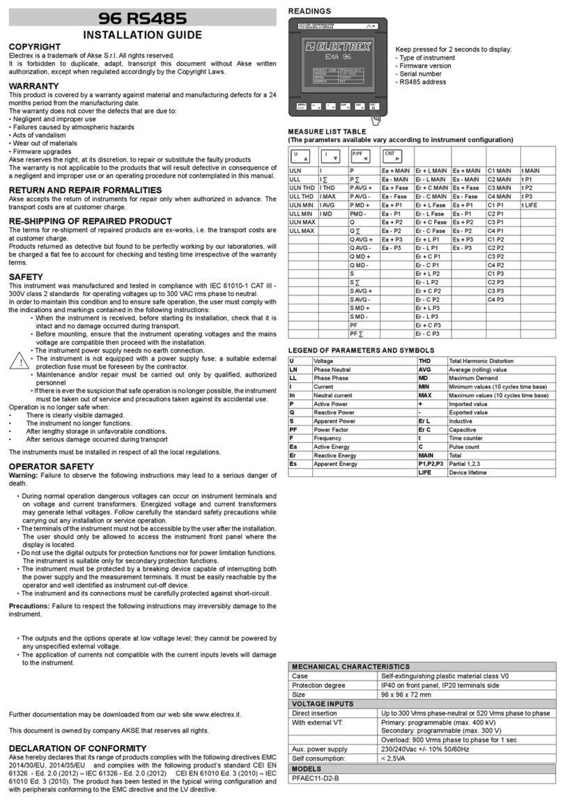
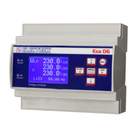
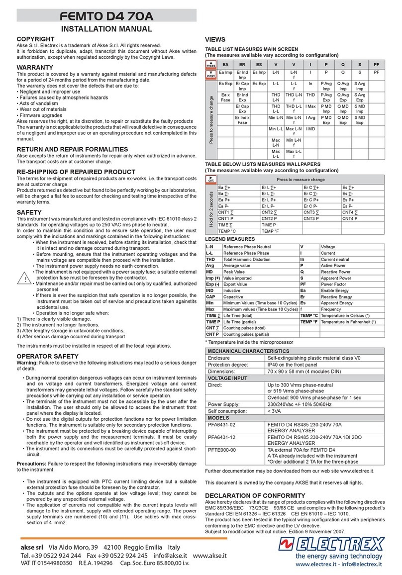
This instructions manual is common to both the instruments type X3M-D
and Flash-D.
COPYRIGHT
Akse S.r.l. All rights are reserved.
It is forbidden to duplicate, adapt, transcript this document without Akse written
authorization, except when regulated accordingly by the Copyright Laws.
Copyright© 2003-2004
WARRANTY
This product is covered by a warranty against material and manufacturing defects for a
period of 36 months period from the manufacturing date
The warranty does not cover the defects that are due to:
• Negligent and improper use
• Failures caused by atmospheric hazards
• Acts of vandalism
• Wear out of materials
Akse reserves the right, at its discretion, to repair or substitute the faulty products
The warranty is not applicable to the products that will result defective in consequence
of a negligent and improper use or an operating procedure not contemplated in this
manual.
RETURN AND REPAIR FORMALITIES
Akse accepts the return of instruments for repair only when authorized in advance.
For instrument purchased directly, the repair authorization must be requested to
Electrex directly by using the enclosed RMA form.
RE-SHIPPING OF REPAIRED PRODUCT
The terms for re-shipment of repaired products are ex-works, i.e. the transport costs
are at customer charge.
Products returned as detective but found to be perfectly working by our laboratories,
will be charged a fixed fee (40.00 Euro + VAT where applicable) to account for
checking and testing time irrespective of the warranty terms.
Safety
This instrument was manufactured and tested in compliance with IEC 61010 class 2
standards for operating voltages up to 250 VAC rms phase to neutral.
In order to maintain this condition and to ensure safe operation, the user must comply
with the indications and markings contained in the following instructions:
•When the instrument is received, before starting its installation, check that
it is intact and no damage occurred during transport.
•Before mounting, ensure that the instrument operating voltages and the
mains voltage are compatible then proceed with the installation.
•The instrument power supply needs no earth connection.
•The instrument is not equipped with a power supply fuse; a suitable
external protection fuse must be foreseen by the contractor.
•Maintenance and/or repair must be carried out only by qualified, authorized
personnel
•If there is ever the suspicion that safe operation is no longer possible, the
instrument must be taken out of service and precautions taken against its
accidental use.
•Operation is no longer safe when:
1) There is clearly visible damage.
2) The instrument no longer functions.
3) After lengthy storage in unfavorable conditions.
4) After serious damage occurred during transport
The instruments X3M and Flash-N must be installed in respect of all the local
regulations.
Operator safety
Warning:Failure to observe the following instructions may lead to a serious danger of
death.
-During normal operation dangerous voltages can occur on instrument terminals
and on voltage and current transformers. Energized voltage and current
transformers may generate lethal voltages. Follow carefully the standard safety
precautions while carrying out any installation or service operation.
-The terminals of the instrument must not be accessible by the user after the
installation. The user should only be allowed to access the instrument front panel
where the display is located.
-Do not use the digital outputs for protection functions nor for power limitation
functions. The instrument is suitable only for secondary protection functions.
-The instrument must be protected by a breaking device capable of interrupting
both the power supply and the measurement terminals. It must be easily reachable
by the operator and well identified as instrument cut-off device.
-The instrument and its connections must be carefully protected against short-
circuit.
Precautions: Failure to respect the following instructions may irreversibly damage to
the instrument.
-The instrument is equipped with PTC current limiting device but a suitable external
protection fuse should be foreseen by the contractor.
-The outputs and the options operate at low voltage level; they cannot be powered by
any unspecified external voltage.
-The application of currents not compatible with the current inputs levels will damage
to the instrument.
Mounting
Instruments size (mm)
Fixing and blocking
The instrument (as well as the optional modules) are fixed to the DIN rail by
means of the spring clip located on the rear side of the unit
Wiring diagrams
Power supply
The instrument is fitted with a separate power
supply with extended operating range. The power
supply terminals are numbered (10) and (11). Use
cables with max cross-section of 4 mm2.
Voltage connection
Connessioni voltmetriche
Use cables with max cross-section of 4 mm2and connect them to the
terminals marked VOLTAGE INPUT on the instrument according to the
applicable diagrams that follow.
Current connection
It is necessary to use external CTs with a primary rating adequate to the load
to be metered and with a 5A secondary rating. The number of CTs to be
used (1, 2 or 3) depends upon the type of network.
Connect the CT output(s) to the terminals marked CURRENT INPUT of the
instrument according to the applicable diagrams that follow.
Use cables with cross-section adequate to the VA rating of the CT and to the
distance to be covered. The max cross-section for the terminals is 4 mm2.
N.B. The CT secondary must always be in short circuit when not connected
to the instrument in order to avoid damages and risks for the operator.
Warning: THE PHASE RELATIONSHIP AMONG VOLTAGE AND
CURRENT SIGNALS MUST BE CAREFULLY RESPECTED. ALL
DISREGARD OF THIS RULE OR OF THE WIRING DIAGRAM LEADS
TO SEVERE MEASUREMENT ERRORS.


