Aktino 3000 Series Instruction Manual

FUSE
STATUS
ALARM
MULTI PAIR
DS3
STATUS
PAIR STATUS
21 34567
14131110 1289
CRAFT
ACO
FAN
ALM
BAT B
BAT A
AK100F
AK301C
CO DS3
SPAN
AK3000 DS3 System
Installation and Maintenance Practice
CONTENTS
Overview.......................................................................1
Safety and Warnings .....................................................2
Introduction...................................................................4
Installation.....................................................................5
Mounting the Shelf...................................................5
Connections ..............................................................6
Front Panel ...............................................................8
Provisioning ..................................................................9
Alarms.........................................................................24
Performance Monitoring .............................................26
Tools & Menu bar .......................................................32
Warranty and Customer Service..................................35
FIGURES
Figure 1 Typical Application Setup ..............................4
Figure 2 Flange Mounting Positions .............................5
Figure 3 Wall Mounting................................................5
Figure 4 AK100S Back Panel .......................................6
Figure 5 Power Block....................................................6
Figure 6 AK3000 Family Front Panel...........................8
TABLES
Table 1 MSPAN Connector Pin Assignments...............7
Table 2 RS-232 DB9 Pin Assignments .........................7
Table 3 Card Front Panel Indicators..............................8
Table 4 Fan Module ACO Pushbutton ..........................8
Table 5 Provisioning Equipment Parameters ..............13
Table 6 DS3 Provisioning Parameters.........................14
Table 7 DS1 Provisioning Parameters.........................15
Table 8 ATM Inband Parameters................................16
Table 8 AUX Alarm Parameters .................................17
Table 9 SNMP Parameters ..........................................18
Table 10 MSPAN Provisioning Parameters................20
Table 11 MSPAN Advanced Parameters ....................20
Table 12 PAIR Provisioning Parameters.....................21
Table 13 Alarm Log ....................................................24
Table 14 Alarm History ..............................................25
Table 15 DS3 Performance Monitoring Parameters....26
Table 16 MSPAN PM Parameters ..............................27
Table 17 Summary PM Monitoring Parameters..........29
Table 18 Current 15 Minutes & 24 Hours Pair PM.....30
Overview
The Aktino 3000 product family enables point to point
transport of DS3 and fractional DS3 services over 2 to
14 bonded pairs of copper, optimized for CSA distances
(9kft 26AWG or 12kft 24AWG). The AK3000 DS3
family consists of DS3 Central Office and remote cards
that plug into a 1RU high housing for 19” and 23” racks
and for wall mounting. The remote card is either line
powered by the Central Office card or locally powered.
Aktino products utilize a technology MIMO on DMT
which uses coordinated signal processing over multiple
transceivers to achieve significant performance
improvements over standard DSL technology.
The AK3000 family consists of the Central Office (CO)
unit, the remote unit, and the 1RU shelf. Refer to the
Warranty and Customer Service section for more
information.
Inspection
After unpacking the unit, check for any damage. If
damage is discovered, report it to the transportation
company and to Aktino, Inc. Refer to the Warranty and
Customer Service section for more information.
AK3000 DS3 Product Family 1 Document 180-0005-001 R10

Safety and Warnings
To ensure your safety when servicing and installing this
equipment, please take the following precautions:
A 7.5A to 10.0A UL listed fuse/circuit breaker must be
installed ahead of this unit in the end use building
installation.
A fuse panel must be installed near the unit in
accordance with the National Electrical Code so that it
is accessible to the operator.
A fuse panel must be provided as part of the building
installation in order to provide a UL required
disconnect point.
Be careful when installing or modifying telephone
lines; dangerous voltages can be present. It is unsafe to
install telephone wiring during a lightning storm.
Only qualified personnel should service this system.
The equipment must be connected to a protective
ground in accordance with the instructions provided in
this manual. Improper grounding may result in an
electrical shock.
Follow local grounding practice to ensure a good frame
ground connection to the Aktino chassis. The frame
ground is required for secondary voltage protection.
For performance and safety reasons, only power
supplies listed for use with telephone equipment by a
locally recognized organization should be used with
Aktino equipment.
All wiring external to the product should follow the
local wiring codes.
Use of this product in a manner other than defined in
this installation guide may cause damage to equipment
or injury to personnel.
If a problem has been isolated to this unit, do not
attempt to repair. The unit’s components are not user
serviceable and therefore must not be replaced. Please
return the unit to Aktino for repair.
All fuses on the unit are located in non accessible areas
and are not field serviceable. Please return the unit to
Aktino for repair.
Observe local practice electrostatic discharge
precautions when handling electronic equipment. Do
not hold electronic plugs by their edge. Do not touch
components or circuitry. Use a grounding wrist strap
attached to grounding connection point on the left side
of the chassis. Use only ESD-protective packaging
materials when transporting equipment.
To prevent ESD events when handling this equipment,
ESD shoes or wrist straps should be utilized by all
personnel, or ESD flooring must be present. See Figure
6for location of wrist strap grounding connection point.
Maximum operating ambient temperature is 65˚C.
Never restrict the air flow through the unit’s fan or
vents.
Connect the unit only to a properly rated supply circuit.
Reliable earthing (grounding) of rack-mounted
equipment should be maintained.
The Aktino unit contains a battery for the Real Time
Clock as a convenience to maintain date and time when
unit is unplugged.
CAUTION
Danger of explosion if battery is incorrectly replaced.
Replace only with the same or equivalent type
recommended by Aktino. Dispose of used batteries
according to the manufacturer’s instructions.
UNIT MAY BE CONNECTED TO
MORE THAN ONE POWER
SOURCE. MAINTAIN CAUTION
WHILE SERVICING EQUIPMENT
!
During installation and service do not connect the
chassis to a live power source. Ensure that fuses are
removed from the fuse panel.
This device complies with Part 15 of the FCC rules.
Operation is subject to the following two conditions:
1. This device may not cause harmful interference.
2. This device must accept any interference received,
including interference that may cause undesired
operation.
This product is intended for installation in Restricted
Access Locations only.
AK3000 DS3 Product Family 2 Document 180-0005-001 R10

The Aktino AK3000 Multi Pair span interface is
designed to coordinate with either a standard 300 Vdc
gas tube protector unit or with a standard 300V solid-
state protector. Carbon block protectors shall not be
used. The 300Vdc gas tube protector shall have the
performance characteristics as follows:
-DC Breakdown Voltage (Max.) 475 V @
2000V/sec
-Impulse Breakdown Voltage (Max.) 650 V max @
100 V/µsec
The 300V dc solid-state protector shall have a
maximum impulse breakdown voltage of 400 V at 100
V/µsec, 1000 V/µsec and 10000 V/µsec.
NOTE: If line powering is enabled, voltage on
MSPAN pairs is either -135Vdc or -185Vdc.
The effective capacitance of the units between the
connection points for the conductors of the tip and ring
is 43.5uF. The effective capacitance of the units
between the connection point for one conductor of tip
or ring and earth is 0.05uF.
At the time of installation, a system assessment shall be
carried out to ensure that the effective capacitance of
the total system, including the capacitance of the
equipment, does not exceed the values specified in
UL60950.
At the time of installation, it shall be checked that the
voltage rating of the wiring of the telecommunication
network is adequate for the normal Aktino unit’s circuit
voltage, together with superimposed transients.
At the time of installation, it shall be checked that the
circuits to be connected together are all AK3000 family
units.
AK3000 DS3 Product Family 3 Document 180-0005-001 R10

Introduction
Aktino’s AK3000 family allows transport of DS3 or
Fractional DS3 over bonded copper pairs. A link
consists of a CO unit and an RT unit. Two types of CO
units are available, one that provides line powering of
the RT unit and one that does not. The RT unit is
capable of being line powered by the CO unit or locally
powered by a -48Vdc power supply.
The CO unit is mounted in CO racks or in Remote
Terminals. Both the CO and RT units are hardened for
operation in both CO and outside plant. The RT unit is
mounted at the customer premises in a rack or on a wall.
Both the CO and RT cards use the same chassis.
Multiple pairs are connected between the CO and RT
units. The Aktino units are rate adaptable which allows
DS3 rates at CSA reaches and Fractional DS3 rates over
CSA reaches.
The Aktino units are carrier class providing all the
required and familiar CO connections. Ease of
deployment is designed into the Aktino products to
make installation quick and easy.
This installation and maintenance practice goes through
the steps required for successful turnup. It is very
detailed to cover most questions and issues that may
arise during installation and maintenance. The Aktino
AK3000 Quick Installation guide (Document 180-0006-
001) is normally sufficient to install the product with the
practice used as a reference.
The steps are detailed in the table of contents.
Generally, steps are installation of the units at the CO
and customer premise, initialization of the management
IP address, quick provisioning, and system health
verification.
Figure 1 shows the typical application setup for the
Aktino product.
Operations Center
Figure 1 Typical Application Setup
Craft Port
Bonded
Copper Pairs
CO
LAN
LAN Ports
Line Unit Remote Unit
Modem Port
TL1
GUI Craft Port
LAN Port
TL1
GUI
DS3
Alarm Relays
DS3
Central Office Customer Premises
AK3000 DS3 Product Family 4 Document 180-0005-001 R10

Installation
The AK100S chassis is used for both the CO and RT installations.
Mounting the Shelf
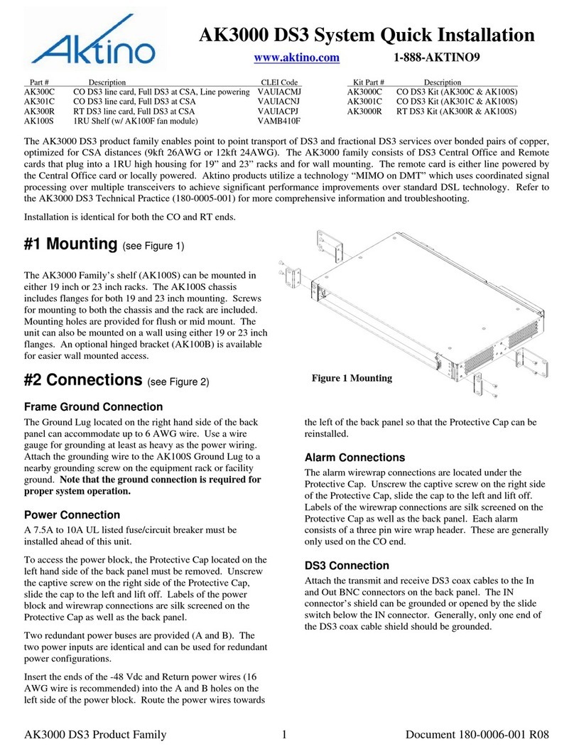
The Aktino AK3000 Family’s shelf (AK100S) can be
mounted in either 19 inch or 23 inch racks. The 19 and
23 inch flanges and mounting screws are included in
the installation kit. Mounting holes are provided for
flush or mid mount. Note that the mid mount flange
can be mounted forward or backward for either 5 or 6
inch recess. Figure 2 shows examples of 19 inch
flanges attached to the flush position and 23 inch
flanges attached to the mid mount position.
The unit can also be mounted on a wall using either 19
or 23 inch flanges. See Figure 3. An optional hinged
bracket (AK100B) is available for easier wall mounted
access.
It is not necessary for the flange to be bonded with the
frame; the AK100S Ground Lug on the back of the
shelf provides proper grounding.
NOTE The fan filter should be replaced every six
months. Ordering information can be found at the end
of this document.
Figure 2 Flange Mounting Positions
Figure 3 Wall Mounting
AK3000 DS3 Product Family 5 Document 180-0005-001 R10

POWER OPEN
IN
DS3
OUT ETHERNET 1 ETHERNET 2
MANAGEMENT MODEM
AUD
AUX2
AUX1
ACO
-48V B
RTN B S
-2
1
NO
COM
A
CLK IN
BITS
-48V A
RTN A +
ALARM IN
BNC ALARM
OUT
AUD
MAJCRIT AUDVIS VIS SYS
MIN IDVIS
MULTI PAIR SPAN
GND
Figure 4 AK100S Back Panel
Connections
Frame Ground Connection
The Ground Lug located on the right hand side of the
back panel (see
Figure 4) can accommodate up to 6 AWG wire. Use a
wire gauge for grounding at least as heavy as the power
wiring. Attach the grounding wire to the AK100S
Ground Lug to a nearby grounding screw on the
equipment rack or facility ground. Test the ground
connection with an ohm meter; there should be less
than 2 ohms between the AK100S Ground Lug and
facility ground. Note that the ground connection is
required for proper system operation.
Power Connection
A 7.5A to 10A UL listed fuse/circuit breaker must be
installed ahead of this unit.
To access the power block, the Protective Cap located
on the left hand side of the back panel (see
Figure 4) must be removed. Unscrew the captive screw
on the right side of the Protective Cap, slide the cap to
the left and lift off. Labels of the power block and
wirewrap connections are silk screened on the
Protective Cap as well as the back panel.
Two redundant power buses are provided (A and B).
The two power inputs are identical and can be used for
redundant power configurations.
Unscrew the captive screw on the power block (see
Figure 5). Insert the ends of the -48 Vdc and Return
power wires (16 AWG wire is recommended) into the
A and B holes on the left side of the power block.
Route the power wires towards the left of the back
panel so that the Protective Cap can be reinstalled.
NOTE: The DC return terminal is not connected to the
equipment frame or the grounding means of the
equipment (Isolated DC Return).
Figure 5 Power Block
-48 V A
RTN A
-48 V B
RTN B
Protective ca
p
AUD
AUX2
AUX1
ACO
-48V B
RTN B S
-2
1
NO
COM
A
CLK IN
BITS
-48V A
RTN A +
ALARM IN
BNC ALARM
OUT
MAJCRIT AUDVIS AUD SYS
MIN IDVISVIS
ETHERNET 1 ETHERNET 2
MANAGEMENT MODEM
Ground Lug
MULTI PAIR SPAN
Tie wrap points
IN
DS3
OUT
OPEN
GND
Use Ethernet 1 onl
y
AK3000 DS3 Product Family 6 Document 180-0005-001 R10

MSPAN Connection
The MSPAN connector (see Figure 4) is used to
connect the Aktino 3000 to the outside plant pairs.
The table below specifies the 50 pin AMP connector
pin assignments.
Table 1 MSPAN Connector Pin Assignments
TIP RING
Pair 1 26 1
Pair 2 27 2
Pair 3 28 3
Pair 4 29 4
Pair 5 30 5
Pair 6 31 6
Pair 7 32 7
Pair 8 33 8
Pair 9 34 9
Pair 10 35 10
Pair 11 36 11
Pair 12 37 12
Pair 13 38 13
Pair 14 39 14
The CO MSPAN cable should be shielded with a pigtail
wire that attaches to the ground lug just above the
MSPAN connector. The RT MSPAN cable’s shield
should NOT be connected to ground (leave open). Tie
wrap points are available in several places on the back
panel. The MSPAN cable can be routed to the left or
right.
Alarm Connections
Alarm connections are generally used on the CO end.
The alarm wirewrap connections are located under the
Protective Cap (see Figure 4). Unscrew the captive
screw on the right side of the Protective Cap, slide the
cap to the left and lift off. Labels of the wirewrap
connections are silk screened on the Protective Cap as
well as the back panel. Each alarm consists of a three
pin wire wrap header. Alarm connections available are:
-Critical, audio and visual
-Major, audio and visual
-Minor, audio and visual
-SysID
-Alarm CutOff (ACO)
-Aux1, Aux2 Alarm In
Each alarm can be connected to Normally Open (NO)
or Normally Closed (NC) position. Use the Common
(COM) pin to complete the connection. SysID
wirewrap contacts can be used to identify the
equipment in alarm. SysID is active during any alarm
activation. Aux1 and Aux2 are input alarm dry contact
relay points. The Alarm CutOff (ACO) wirewrap pins
are input dry contact relay points used for remote
activation of ACO. The BITS Clock wirewrap pins are
reserved for future use.
DS3 Connection
Attach the transmit and receive DS3 coax cables to the
In and Out BNC connectors on the back panel (see
Figure 4 ). The IN connector’s shield can be grounded
or opened by the slide switch below the IN connector.
Generally, only one end of the DS3 coax cable shield
should be grounded.
Management Connections
Ethernet 1 female RJ-45 port (located on the back
panel) can be used for local or remote management
access. The Ethernet port automatically is set to either
10BaseT or 100BaseT and auto-sense the polarity of
TX/RX (automatic MDIX). Ethernet 2 port is not
available.
Caution To order to comply with the intrabuilding
lightning surge requirements, intrabuilding Ethernet
management wiring must be shielded, and the shield for
the wiring must be grounded at both ends.
The back panel RS232 modem port is not usable with
R3.2.x software.
The front panel Craft port is used for command line
access using a terminal emulator program; AktinoView
is not supported on the craft port except for IP
initialization. The DB-9 female RS232 port pin
assignments are shown below; note that only pins 2, 3,
and 5 are active on the front panel Craft port.
For both the back panel RS232 modem port and the
front panel Craft port, the settings are 9600 baud, 8 data
bits, no parity, and 1 stop bit.
Management is generally attached at the CO end.
Table 2 RS-232 DB9 Pin Assignments
RS-232 Signal Pin
DCD 1
Receive Data* 2
Transmit Data* 3
DTR 4
Ground* 5
DSR 6
RTS 7
CTS 8
RI 9
* Front panel Craft port uses pins 2, 3, and 5 only.
AK3000 DS3 Product Family 7 Document 180-0005-001 R10

Front Panel
Figure 6 shows the AK3000 family front panel. The AK3000 family kits consist of an AK3xx Line card and the
AK100S shelf. The AK100F fan module is included with the AK100S shelf. The CO and RT kits have identical front
panel indicators and functions.
Figure 6 AK3000 Family Front PanelFigure 6 AK3000 Family Front Panel
Table 3 Card Front Panel IndicatorsTable 3 Card Front Panel Indicators
LEDLED ConditionCondition FunctionFunction
STATUS
Off
Green
Re
d
Power off
Normal
Card malfunction
FUSE Off
Re
d
Unit fuse o
k
Unit fuse has blown
ALARM
Solid green
Solid yellow
Solid red
Nor
m
al
Minor Alarm active
Critical or Major Alarm
active
DS3
STATUS
Solid green
Solid yellow
Solid re
d
Normal
Network or Customer AIS
Network or Customer LOS
MULTIPAIR
SPAN
Solid green
Solid yellow
Solid re
d
Normal
Minor Alarm
Critical or Major Alar
m
PAIR
STATUS
Off
Solid green
Flashing green
Solid red
Pair is disable
d
Pair is up
Pair is acquiring
Pair LOS/Open
circuit/Short
BAT A,
BAT B
Off
Solid green
External DC power has not
been applied
External DC power is
p
resent
FAN ALM
Solid green
Solid yellow
Flashing red
Fan status normal
One fan has failed
More than one fan has
faile
d
Table 4 Fan Module ACO Pushbutton
Pushbutton Function
ACO
Push Alarm Cut Off pushbutton for at
least ½ second, deactivates audio (not
visual) relay for all active alarms. The
ALARM LED on the Aktino card
indicates ACO has been activated. Note
that ACO can also be activated by the
wirewrap connection on back of unit.
FUSE
STATUS
ALARM
MULTI PA
DS3
STATUS
IR
PAIR STATUS
21 34567
14131110 1289
CRAFT
ACO
FAN
ALM
AK100F
AK301C
CO DS3
SPAN
BAT B
BAT A
Extraction
handle Extraction
handle
FUSE
STATUS
ALARM
MULTI PAIR
DS3
STATUS
PAIR STATUS
21 34567
14131110 1289
SPAN
ACO
ALM
FAN
BAT B
BAT A Alarm Cutoff
Button
Wrist strap
grounding
connection
point Replaceable
Filter
F
Fan module
AK3000 DS3 Product Family 8 Document 180-0005-001 R10

Provisioning
AktinoView GUI V3 software is presented as the preferred means of maintenance access. TL1 commands are available.
AktinoView V3 software is used to provision and monitor the system. Load AktinoView V3 software onto the
maintenance computer per the instructions on the CDROM package.
Note: AktinoWeb web browser is an alternative method of maintenance access. Simply enter the IP address of the
Aktino unit in the address bar of a web browser. Features not available in AktinoWeb vs. AktinoView are:
·System Backup and Restore
·System/Slot Software Upgrade
·Export Alarm Log, Alarm History and PM
·Automatic update for configuration changes from other interfaces (AktinoView, AktinoEMS, CLI)
·No circuit display (CO-RT) for AK5000
Configuring the Management Ethernet Port
AktinoView uses the Ethernet port 1 for access to the
Aktino unit. Generally, the CO unit is used to set up
the system; the RT unit can be provisioned through the
CO unit.
Use one of the two following procedures to configure
the unit’s Management Ethernet port.
Method #1: Initialization using the front panel Craft
port
1) Connect a serial cable between the maintenance
computer and the Aktino unit’s front panel craft
port.
2) Start a terminal program such as HyperTerminal on
the maintenance computer. Parameters are 9600
baud, eight bits, no parity bits, 1 stop bit, and no
handshake.
3) After the unit has finished booting, a prompt
“AKxxxx>” should appear, where xxxx is the part
number of the unit. At the prompt, type
act-user::loginname:::password; See *Note below
for loginname and password values.
4) You will be prompted to enter the following
information:
Enter TID [CO]:
Enter IPAddress [192.168.10.1]:
Enter NetMask [255.255.255.0]:
Enter Gateway [0.0.0.0]:
Enter ProxyIP-Address[0.0.0.0]: (CO only)
Enter Date (yyyy-mm-dd)[2005-08-11]: (CO only)
Enter Time (hh-min-sec)[13-03-24]: (CO only)
5) Inputs can be modified with AktinoView at a later
time. Hit enter to use the default value in the
brackets.
6) Exit the terminal program.
Method #2: Initialization using the Management
Ethernet port
1) Connect an Ethernet cable between the
maintenance computer and the Aktino unit’s
Management Ethernet 1 port located on the back of
the chassis.
2) The Aktino CO and RT units have a factory default
IP address of 192.168.10.1 and 192.168.10.2
respectively.
3) Configure the maintenance computer’s IP address
to 192.168.10.3 and Netmask to 255.255.255.0.
Note the maintenance computer’s original settings.
4) Run AktinoView using 192.168.10.1 (CO) or
192.168.10.2 (RT) as the IP address for the Aktino
unit. Enter the user name and the password*.
5) If desired, the Aktino units can now be provisioned
with AktinoView.
6) If adding the Aktino unit to the local LAN, in the
AktinoView GUI, under “Tools” in the top menu
bar, select “Quick Provisioning”.
7) Configure the Aktino unit’s desired IP address,
subnet mask, and gateway address for the local
LAN.
8) Exit AktinoView.
9) Reconfigure the maintenance computer’s IP
address to original setting.
*NOTE: Default login name and password is
superuser. For system security, the password
for superuser should be changed.
AK3000 DS3 Product Family 9 Document 180-0005-001 R10

Provisioning with AktinoView V3
Note: Use AktinoView V3 to access the most up to date features available.
AktinoView V3 System Requirements
The minimum AktinoView system requirements are:
•Pentium 4 processor-base computer
•Recommended 256Mb, Minimum 128Mb
•Microsoft Windows 2000, XP, or NT
•CD-ROM drive
AktinoView V3 Installation
•Insert the AktinoView CD in the CD ROM drive
•Open Windows Explorer and click on the CD drive option
•Double click on install.exe in the AktinoView folder
•Follow the instructions on the screen
Login Window
Once the Management Ethernet port has been set up, AktinoView should be started to continue with provisioning and
verify the health of the circuit.
Upon running AktinoView V3, a login window will appear:
Enter IP address of the AK3000 unit username, and password. See above *Note for user name and password. To
provide system security, the password for superuser and user accounts should be set up with AktinoView menus.
AK3000 DS3 Product Family 10 Document 180-0005-001 R10

AK3000 DS3 Product Family 11 Document 180-0005-001 R10
After logging on, the main status screen will appear:
Main Status Screen
The window components consist of the following
sections:
Workspace/Summary area
The workspace/summary area shows the CO and RT
units for a quick look at the state of the system. Note
that by positioning the mouse over items in the
overview, a tool tip popup appears with details of the
current state. This area is also used to display
provisioning and performance monitoring info
depending on the tab item selected.
Menu bar
File, Action, and Help along with action icons.
Tabs
Allows navigation of menus for provisioning,
performance monitoring, and alarms.
Alarm summary
A summary of the number of alarms is provided at the
lower part of the window.

Inventory Screen
Selecting the Inventory tab displays information on the system.
Parameter Values
Unit CO or RT unit
Description Unit description
Serial Serial number of unit
CLEI Code Telcordia assigned CLEI code
MAC Address Each unit has a MAC address
Hardware Version Hardware version of the unit
Software Version Software version of the unit
AK3000 DS3 Product Family 12 Document 180-0005-001 R10

Provisioning Equipment Screen
Selecting the Equipment tab under Provisioning allows equipment provisioning of the system. Right click on unit to
bring up Equipment popup. See Table 5 for parameters and values.
Table 5 Provisioning Equipment Parameters
Values
Parameter
System ID (CO only) String describing the System
Contact (CO Only) String describing contact
Location (CO only) String describing location
IP Address IP address of the Aktino unit
Subnet Mask Subnet mask for the Aktino
unit
Gateway Address Gateway address for the Aktino
unit
RT Proxy IP (CO
only)
Proxy IP address for RT - Used
to access RT directly
Allow CPE Mgmt
Access (RT only) YES, NO
Repeater Type (CO
only)
None, Span 1, Span 2
If repeater application, indicate
which span
Other Span IP
Address (CO Only)
If repeater application, indicate
other span IP address (do not
use the same IP address as
management port)
Span 2 Mgmt. IP
Address (CO only)
If Span 2, indicate management
IP address (do not use the same
IP address as management port)
Date and Time (CO
only)
Pull down buttons allow
manual setting of time and
date. “PC Time” sets the
Aktino system to the
maintenance computer’s time
and date. Note that the RT’s
time and date is updated and
periodically synchronized with
the CO.
AK3000 DS3 Product Family 13 Document 180-0005-001 R10

Provisioning DS3 Configuration Screen
Selecting the DS3 tab under CO Unit allows DS3 provisioning of the system. Right click on the unit to bring up DS3
provisioning popup. See Table 6 for parameters and values. Note that some of the parameters changed on the CO are
also reflected on the RT.
Table 6 DS3 Provisioning Parameters
Parameter Values
DS3 Circuit ID Allows input of description
of the DS3 circuit
DS3 Line Format (CO
only)
C-Bit Parity
Asynchronous M13
CO unit DS3 Line Build
Out
0..225ft
226..450ft
Output Mode (Alarm
Pattern) (CO only)
Normal- Idle, Alarm
Indication Signal (AIS)
Payload Type (CO only)
Channelized DS3 (TDM)
ATM*
Scrambled ATM*
Clear Channel
Loopback Timeout (CO
Only) 0, 20, 60, 3600(24 hours)
minutes
FEAC Pass Through (CO
only) YES - DS3 FEAC loopback
messages from the network
are reacted upon by the CO
NO - DS3 FEAC loopback
messages from the network
are ignored
State UP- CO DS3 port is in
service
DOWN- CO DS3 port is out
of service
*ATM PLCP format is not supported
AK3000 DS3 Product Family 14 Document 180-0005-001 R10

Provisioning DS1 Configuration Screen
Selecting the DS1 tab under CO Unit allows DS3 tributary provisioning of the system. Right click on the Index to
bring up DS1 configuration popup. Note that this screen is only active if DS3 Payload Type is set to Channelized DS3
(TDM). The MSPAN rate is set the number of DS1’s set to UP state. See Table 7 for parameters and values.
Table 7 DS1 Provisioning Parameters
Parameter Values
Circuit ID Circuit ID of DS1
Priority 0[Low] through 7[High]
When system needs to downshift
the MSPAN rate during adverse
conditions (e.g. a pair failed), the
priority parameter determines the
order of DS1’s dropped
State
DOWN- DS1 tributary is not
transported
UP- DS1 tributary is transported
AK3000 DS3 Product Family 15 Document 180-0005-001 R10

Provisioning ATM Inband Management
Selecting the ATM Inband tab under Provisioning allows ATM Inband Management provisioning of the system. The
DS3 Payload Type must be in an ATM mode allow setting this item. See Table 8 for parameters and values.
Table 8 ATM Inband Parameters
Parameter Values
VPI Virtual Path Identifier
VCI Virtual Circuit Identifier
IP Address
IP address of the Aktino unit
(must be in a different subnet
vs. the local management port)
Subnet
Mask Subnet mask for the Aktino unit
Default
Gateway
Gateway address for the Aktino
unit
AK3000 DS3 Product Family 16 Document 180-0005-001 R10

Provisioning AUX Alarms Screen
Selecting the AUX Alarms tab under Provisioning allows external alarm provisioning of the system. These parameters
determine how the AUX1 and AUX2 input pins on the Aktino units react. Note that the alarm input pins are Normally
Open (NO). Right click on the Index to bring up the Aux Alarm configuration popup. See Table 9 for parameters and
values.
Table 9 AUX Alarm Parameters
Parameter Values
Alarm Type This value is reported as alarm
type in the TL1 alarm message
Description
This value is reported as alarm
description in the TL1 alarm
message
Severity Critical, Major, Minor
AK3000 DS3 Product Family 17 Document 180-0005-001 R10

Provisioning SNMP Screen
Selecting the SNMP tab allows setting SNMP receiver parameters. Right click on the Index to bring up the Aux
Alarm configuration popup. See Table 10 below for details.
Table 10 SNMP Parameters
Parameter Values
IP Address SNMP Trap receiver IP
Address
Community
String
SNMP defined
community string
Version Version- SNMP V1 or
V2
AK3000 DS3 Product Family 18 Document 180-0005-001 R10

AK3000 DS3 Product Family 19 Document 180-0005-001 R10
Provisioning MSPAN Screen
Selecting the MSPAN tab under Provisioning allows MSPAN provisioning of the system. Right click on the
Parameters line to bring up the either the General or Advanced Parameters. See Table 11 and Table 12 for parameters
and values.

AK3000 DS3 Product Family 20 Document 180-0005-001 R10
Table 11 MSPAN Provisioning Parameters
Parameter Values
Circuit ID Circuit ID, max 48 characters
MSPAN Mode
(R2.10 or higher)
Symmetric
Asymmetric (Valid only when Payload Type is ATM or Scrambled ATM)
MSPAN Rate
Rate Upstream
Rate Downstream
0 to 44224 Kbps
(Valid if Payload Type is ATM or Scrambled ATM. MSPAN Rate for Clear Channel
Payload Type is set to 44736 Kbps. MSPAN Rate for Channelized DS3 Payload Type is set
by the number of DS1’s set to UP State in the DS1 Provisioning tab.)
Line Powering
OFF- RT is local powered
-135v
-185v
SNR Margin [dB] 0 to 18dB. Set value is desired MSPAN margin
Margin Threshold [dB] 0 to 18 (≤SNR Margin) If MSPAN margin falls below Margin Threshold value, an alarm is
set
Reserve Pairs 1 to 13
PSD Mask Auto-Selects mask automatically
Select M1, M2, M3, M4. M5
RT Deployment M1
RT Deployment M2
Upstream 276khz
Repeater Span1: M1
Repeater Span2: M1, M2, M3
Exclude M1 (6kft mask)
Exclude M1, M2 (6/9kft masks)
Exclude M1, M2, M3 (6/9/11.5kft masks)
Exclude M1, M2, M3, M4 (6/9/11.5/13kft masks)
State UP- MSPAN port is in service
DOWN- MSPAN port is out of service
Table 12 MSPAN Advanced Parameters
Parameter Values
Upstream/Downstream
Reed-Solomon
Overhead [%]
Calculated Reed-Solomon
Overhead percentage
RS% = 2 * INP / Latency
Upstream/Downstream
Interleaver Latency
[msec]
0, 2, 4, 6, 8, 12, 16, 20
msec
Latency of the PHY
Upstream/Downstream
Impulse Noise
Protection (INP)
[usec]
50, 125, 250, 500, 750,
1000 usec
Length of noise protection
Upstream/Downstream
Power Back-Off [dB]
Auto, -3 to 16 dB
This manual suits for next models
1
Table of contents
Other Aktino Network Hardware manuals
Popular Network Hardware manuals by other brands

Matrix Switch Corporation
Matrix Switch Corporation MSC-2HD3216L product manual

Planet Networking & Communication
Planet Networking & Communication NVR-810 user manual

Cisco
Cisco Content Delivery Engine 100/200/300/400 Hardware installation guide

Qvis
Qvis IZEUS 7000 NVR RANGE user manual

EMD Storage
EMD Storage SecurStor 16i installation manual

Lantronix
Lantronix SISPM1040-582-LRT quick start guide