Aktino AK4000 Series Original operating instructions

AK4000 Ethernet Product Family 1 Document 180-0008-001 R08
Part # Description CLEI Code Kit Part # Description
AK400C CO Ethernet line card, 50 Mbps at CSA, Line powering VAUIAG8J AK4000C CO Ethernet Kit (AK400C & AK100S)
AK401C CO Ethernet line card, 50 Mbps at CSA VAUIAG9J AK4001C CO Ethernet Kit (AK401C & AK100S)
AK400R RT Ethernet line card, 50 Mbps at CSA VAUIAHAJ AK4000R RT Ethernet Kit (AK400R & AK100S)
AK410C CO Ethernet line card, 25 Mbps at CSA, 45 Mbps max, Line powering VAUIACWJ AK4010C CO Ethernet Kit (AK410C & AK100S)
AK411C CO Ethernet line card, 25 Mbps at CSA, 45 Mbps max VAUIACXJ AK4011C CO Ethernet Kit (AK411C & AK100S)
AK410R RT Ethernet line card, 25 Mbps at CSA, 45 Mbps max VAUIACYJ AK4010R RT Ethernet Kit (AK410R & AK100S)
AK420C CO Ethernet line card, 10 Mbps at CSA, 20 Mbps max, Line powering VAUIAFZJ AK4020C CO Ethernet Kit (AK420C & AK100S)
AK421C CO Ethernet line card, 10 Mbps at CSA, 20 Mbps max VAUIAF0J AK4021C CO Ethernet Kit (AK421C & AK100S)
AK420R RT Ethernet line card, 10 Mbps at CSA, 20 Mbps max VAUIAF1J AK4020R RT Ethernet Kit (AK420R & AK100S)
AK100S 1RU Shelf (w/ AK100F fan module) VAMB410F
The AK4000 Ethernet product family enables point to point transport of Ethernet services over bonded pairs of copper, optimized
for CSA distances (9kft 26AWG or 12kft 24AWG). The AK4000 family consists of Ethernet Central Office and Remote cards
that plug into a 1RU high housing for 19” and 23” racks and for wall mounting. The remote card is either line powered by the
Central Office card or locally powered. Aktino products utilize a technology “MIMO on DMT” which uses coordinated signal
processing over multiple transceivers to achieve significant performance improvements over standard DSL technology. Refer to
the AK4000 Ethernet Technical Practice (180-0007-001) for more comprehensive information and troubleshooting.
Installation is identical for both the CO and RT ends.
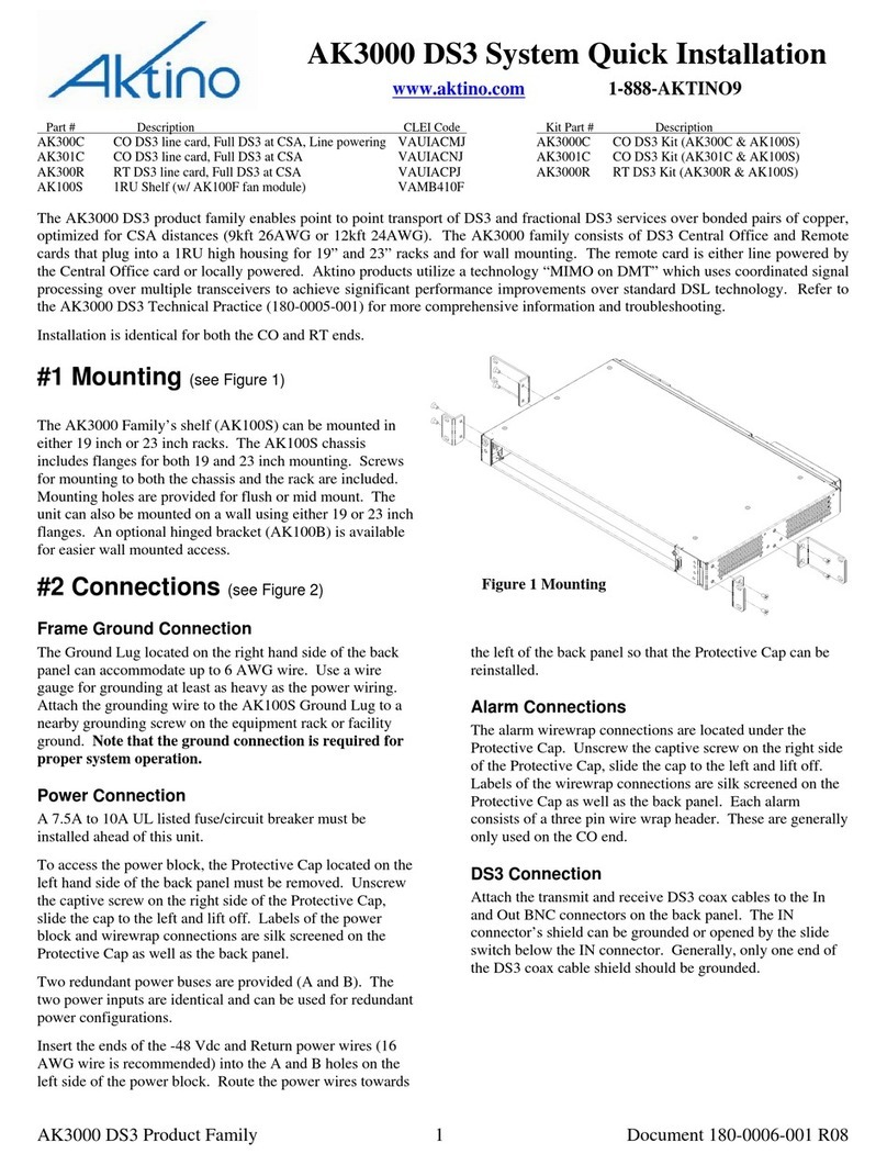
#1 Mounting (see Figure 1)
The AK4000 Family’s shelf (AK100S) can be mounted in
either 19 inch or 23 inch racks. The AK100S chassis
includes flanges for both 19 and 23 inch mounting. Screws
for mounting to both the chassis and the rack are included.
Mounting holes are provided for flush or mid mount. The
unit can also be mounted on a wall using either 19 or 23 inch
flanges. An optional hinged bracket (AK100B) is available
for easier wall mounted access.
#2 Connections
Frame Ground Connection (see Figure 2)
The Ground Lug located on the right hand side of the back
panel can accommodate up to 6 AWG wire. Use a wire
gauge for grounding at least as heavy as the power wiring.
Attach the grounding wire to the AK100S Ground Lug to a
nearby grounding screw on the equipment rack or facility
ground. Note that the ground connection is required for
proper system operation.
Power Connection (see Figure 2)
A 7.5A to 10A UL listed fuse/circuit breaker must be
installed ahead of this unit.
To access the power block, the Protective Cap located on the
left hand side of the back panel must be removed. Unscrew
the captive screw on the right side of the Protective Cap,
slide the cap to the left and lift off. Labels of the power
block and wirewrap connections are silk screened on the
Protective Cap as well as the back panel.
Two redundant power buses are provided (A and B). The
two power inputs are identical and can be used for redundant
power configurations. Insert the ends of the -48 Vdc and
Return power wires (16 AWG wire is recommended) into
the A and B holes on the left side of the power block. Route
the power wires towards the left of the back panel so that the
Protective Cap can be reinstalled.
Alarm Connections (see Figure 2)
The alarm wirewrap connections are located under the
Protective Cap. Unscrew the captive screw on the right side
of the Protective Cap, slide the cap to the left and lift off.
Labels of the wirewrap connections are silk screened on the
Protective Cap as well as the back panel. Each alarm
consists of a three pin wire wrap header. These are generally
only used on the CO end.
Ethernet Data Connections (Figure 3)
Attach Ethernet data cables to any of the four 10/100BaseT
RJ45 plugs on the front panel.
Caution To order to comply with the intrabuilding
lightning surge requirements, intrabuilding Ethernet wiring
must be shielded, and the shield for the wiring must be
grounded at both ends.
AK4000 Ethernet System Quick Installation
www.aktino.com 1-888-AKTINO9
Figure 1 Mounting

AK4000 Ethernet Product Family 2 Document 180-0008-001 R08
Management Connection
Ethernet 1 female RJ-45 port (located on the back panel) can
be used for local or remote management access. The
Ethernet port automatically is set to either 10BaseT or
100BaseT and auto-sense the polarity of TX/RX (automatic
MDIX). Ethernet 2 port is not available.
Caution To order to comply with the intrabuilding
lightning surge requirements, intrabuilding Ethernet
management wiring must be shielded, and the shield for the
wiring must be grounded at both ends.
The back panel RS232 modem port can be used for local or
remote management access. The port is set for PPP
communication for telnet or AktinoView GUI access.
The front panel Craft port is used for command line access
using a terminal emulator program; AktinoView is not
supported on the craft port except for IP initialization.
Management is generally attached at the CO end.
MSPAN Connection
The MSPAN connector is used to connect the Aktino 4000
to the outside plant pairs. The CO MSPAN cable should be
shielded with a pigtail wire that attaches to the ground lug
just above the MSPAN connector. The RT MSPAN cable’s
shield should NOT be connected to ground (leave open).
The MSPAN cable is female. Tie wrap points are available
in several places on the back panel. The MSPAN cable can
be routed to the left or right.
Table 1 specifies the standard 50 pin AMP connector pin
assignments.
Table 1 MSPAN Connector Pin Assignments
TIP RING
Pair 1 26 1
Pair 2 27 2
Pair 3 28 3
Pair 4 29 4
Pair 5* 30 5
Pair 6* 31 6
Pair 7* 32 7
Pair 8* 33 8
Pair 9* 34 9
Pair 10* 35 10
Pair 11* 36 11
Pair 12* 37 12
Pair 13* 38 13
Pair 14* 39 14
* Note that only the first four pairs are active on the AK42x
products and only the first eight pairs are active on the
AK41x products.
POWER OPEN
IN
DS3
OUT ETHERNET 1 ETHERNET 2
MANAGEMENT MODEM
AUD
AUX2
AUX1
ACO
-48V B
RTN B S
-2
1
NO
COM
A
CLK IN
BITS
-48V A
RTN A +
ALARM IN
BNC ALARM
OUT
AUD
MAJCRIT AUDVIS VIS SYS
MIN IDVIS
MULTI PAIR SPAN
GND
Protective ca
p
AUD
AUX2
AUX1
ACO
-48V B
RTN B S
-2
1
NO
COM
A
CLK IN
BITS
-48V A
RTN A +
ALARM IN
BNC ALARM
OUT
AUD
MAJCRIT AUDVIS VIS SYS
MIN IDVIS
ETHERNET 1 ETHERNET 2
MANAGEMENT MODEM
Ground Lug
MULTI PAIR SPAN
Tie wrap points
Use Ethernet 1 onl
y
Fi
g
ure 2 AK100S Back Panel
Multi pair span connector is male; cable is female.

AK4000 Ethernet Product Family 3 Document 180-0008-001 R08
#3 Provisioning (see Table 2)
AktinoView software is used to provision and monitor the
system. Use AktinoView V3 to access the most up to date
features available. Load AktinoView software onto the
maintenance computer per the instructions on the CDROM
package.
Configuring Management Ethernet Port
AktinoView uses the Ethernet port 1 for access to the Aktino
unit. Generally, the CO unit is used to set up the system; the
RT unit can be provisioned through the CO unit.
Use one of the two following procedures to configure the
unit’s Management Ethernet port.
Method #1: Initialization using the front panel Craft port
1) Connect a serial cable between the maintenance
computer and the Aktino unit’s front panel craft port.
2) Start a terminal program such as HyperTerminal on the
maintenance computer. Parameters are 9600 baud, eight
bits, no parity bits, 1 stop bit, and no handshake.
3) After the unit has finished booting, a prompt
“AKxxxx>” should appear, where xxxx is the part
number of the unit. At the prompt, type bolded item:
AKxxxx> enable
4) At prompt login: type the login name*
5) At prompt Password: type the password*
6) You will be prompted to enter the following
information:
Enter TID [CO]:
Enter IPAddress [192.168.10.1]:
Enter NetMask [255.255.255.0]:
Enter Gateway [0.0.0.0]:
Enter ProxyIP-Address[0.0.0.0]: (CO only)
Enter Date (yyyy-mm-dd)[2005-08-11]: (CO only)
Enter Time (hh-min-sec)[13-03-24]: (CO only)
7) Inputs can be modified with AktinoView at a later time.
Hit enter to use the default value in the brackets.
8) Exit the terminal program.
Method #2: Initialization using the Management
Ethernet port
1) Connect an Ethernet cable between the maintenance
computer and the Aktino unit’s Management Ethernet 1
port located on the back of the chassis.
2) The Aktino CO and RT units have a factory default IP
address of 192.168.10.1 and 192.168.10.2 respectively.
3) Configure the maintenance computer’s IP address to
192.168.10.3 and Netmask to 255.255.255.0. Note the
maintenance computer’s original settings.
4) Run AktinoView using 192.168.10.1 (CO) or
192.168.10.2 (RT) as the IP address for the Aktino unit.
Enter the user name and the password*.
5) If desired, the Aktino units can now be provisioned with
AktinoView.
6) If adding the Aktino unit to the local LAN, in the
AktinoView GUI, under “Tools” in the top menu bar,
select “Quick Provisioning”.
7) Configure the Aktino unit’s desired IP address, subnet
mask, and gateway address for the local LAN.
8) Exit AktinoView.
9) Reconfigure the maintenance computer’s IP address to
original setting.
Provisioning with AktinoView V3
Connect the Aktino unit’s Ethernet 1 port to the local LAN.
Once the Management Ethernet port has been set up,
AktinoView V3 should be started to provision the circuit.
See Table 2 below for common provisioning parameters
under the AktinoView V3 Provisioning tab.
Table 2 Common Provisioning Selections
Parameter Values
MSPAN Rate Rate (Kbps)
# Pairs
1 to 4 (AK42x), 1 to 8 (AK41x),
1 to 14 (AK40x)
Individual pairs can be set to UP or
DOWN in the Pair menu
Line Powering Off, -135v, -185v (-185v default)
Note, line powering is not available
on the AK4x1 products.
MSPAN SNR Margin
(MSPAN menu) 0..18db (5db default)
Ethernet Parameters Each port’s parameter values can be
p
rovisioned in the Ethernet Menus
*NOTE: Default login name and password is
superuser. For system security, the password for
superuser should be changed.

AK4000 Ethernet Product Family 4 Document 180-0008-001 R08
#4 System Health Verification
As soon as power is applied to the CO unit (and the RT unit
if locally powered), the system automatically starts up. The
front panel indicators show the status of the system (see
Figure 3 and Table 4). If any of the LED’s is not Normal,
AktinoView can be used to determine the source of the
problem.
AktinoView main status screen shows an overview of the
system. Performance monitoring for Ethernet, MSPAN, and
Pair is available through the tree menu. Current system
alarms (see Table 3) are displayed on the main status screen.
Alarm history and logs are available through the tree menu.
Table 3 Common Alarms (displayed by AktinoView)
Alarm Fault Troubleshooting
MSPAN LOS MultiPair Span pairs are down, check pairs
MSPAN Capacity
MultiPair Span capacity below configured
rate; increase number of pairs or decrease
system margin or reduce rate. Check Pairs
PM to ensure proper operation.
Pair LOS Pair is connected but not receiving signal,
check Pair PM.
Pair Open Circuit Pair is not connecte
d
Table 4 Front Panel Indicators
LED Condition Function
STATUS
Off
Green
Re
d
Power off
Normal
Card malfunction
FUSE Off
Re
d
Unit fuse ok
Unit fuse has blown
ALARM
Solid green
Solid yellow
Solid re
d
Normal
Minor Alarm active
Critical or Major Alarm active
MULTIPAIR
SPAN
Solid green
Solid yellow
Solid
r
e
d
Normal
Minor Alarm
Critical or Major Alar
m
PAIR
STATUS
Off
Solid green
Flashing green
Solid re
d
Pair is disabled
Pair is up
Pair is acquiring
Pai
r
LOS/Open circuit/Short
BAT A,
BAT B Off
Solid green
External DC power has not been
applied
External DC power is present
FAN ALM
Solid green
Solid yellow
Flashing re
d
Fan status normal
One fan has failed
More than one fan has faile
d
Figure 3 AK4000 Front Panel (AK41x unit shown)
4321
PAIR STATUS
8765
10/100BASE-T
1234
CO ENET
AK410C
SPAN
MULTI PAIR
ALARM
STATUS
FUSE
CRAFT
AK100F
FAN
ACO
ALM
BAT B
BAT A
4321
PAIR STATUS
8765
SPAN
MULTI PAIR
ALARM
STATUS
FUSE
ACO
ALM
FAN
BAT B
BAT A
F
Alarm Cutoff
Button
Extraction
handle Extraction
handle Fan module
Replaceable
Filter
10/100BASE-T
1234
This manual suits for next models
19
Other Aktino Network Hardware manuals