Akytec INS-F1 User manual

akYtec GmbH · Vahrenwalder Str. 269 A · 30179 Hannover · Germany · Tel.: +49 (0) 511 16 59 672-0 · www.akytec.de
1
Contents
1Safety guidelines...........................................................................................................................................2
1.1 Definitions.....................................................................................................................................................................................2
1.2 General instructions.....................................................................................................................................................................2
2Intended use..................................................................................................................................................2
3Specifications................................................................................................................................................3
4Description ....................................................................................................................................................3
5Installation .....................................................................................................................................................3
6Electrical wiring.............................................................................................................................................4
7Operation.......................................................................................................................................................4
8Maintenance ..................................................................................................................................................4
9Transportation and storage.........................................................................................................................5
10 Scope of delivery ..........................................................................................................................................5
Appendix A. Dimensions ....................................................................................................................................5

akYtec GmbH · Vahrenwalder Str. 269 A · 30179 Hannover · Germany · Tel.: +49 (0) 511 16 59 672-0 · www.akytec.de
2
1 Safety guidelines
1.1 Definitions
DANGER
DANGER indicates an imminently hazardous situation which, if not avoided, will
result in death or serious injury.
WARNING
WARNING indicates a potentially hazardous situation which, if not avoided, could
result in death or serious injury.
CAUTION
CAUTION indicates a potentially hazardous situation which, if not avoided, could
result in minor or moderate injury.
►
NOTICE
NOTICE indicates a potentially harmful situation which, if not avoided, may result
in damage of the product itself or of adjacent objects.
1.2 General instructions
DANGER
Dangerous voltage
Electric shock currents could kill or seriously injure.
All electrical connections must be performed by a fully qualified electrician.
Ensure that the mains voltage matches the voltage marked on the nameplate!
Ensure that the device is provided with its own power supply line and electric
fuse!
Even when the auxiliary power is switched off the unit terminals can carry
dangerous voltage! Switch off the auxiliary voltage and the measured voltage
when working on the device!
WARNING
Improper use
Improper use of the device can cause personal injury, property or environmental damage.
Follow the maintenance instructions and use only original spare parts from the
manufacturer!
The manufacturer shall not be liable for claims of any type based on operation contrary to
the intended use!
CAUTION
Improper installation
Improper installation can cause serious or minor injuries and damage the device.
Installation must be performed only by fully qualified personnel.
2 Intended use
The INS-F1 is a digital voltmeter for measuring effective voltage from 5 to 400 V AC. The
device requires 24 V DC auxiliary voltage. It is designed for use in industrial applications.
The device may only be operated
– properly installed and
– in accordance with the specifications.
Improper use
– The device should not be used for medical devices which receive, control or otherwise
affect human life or physical health.
– The device should not be used in an explosive environment.
– The device should not be used in an atmosphere with chemi-cally active substance.

akYtec GmbH · Vahrenwalder Str. 269 A · 30179 Hannover · Germany Tel.: +49 (0) 511 16 59 672-0 · www.akytec.de
3
3 Specifications
Table 3.1 Specifications
Power supply
24 (8…30) V DC
Input signal
5…400 V AC, (50±25%) Hz
Inputs
1
Power consumption, max.
4 W
Input resistance, min.
500 kohm
Accuracy
0.25% + 1 digit
Display
LED, 4 digits, 7 segment
Character height
14 mm
Display color
red
Sampling rate
1 reading / s
IP Code
front IP65, rear IP20
Dimensions
48 x 26 x 65 mm
Weight
approx. 30 g
Protection class
II
Ambient temperature
-20…+50 °C
Storage temperature
-25…+55 °C
Humidity
up 80% at 35°C (non-condensing)
4 Description
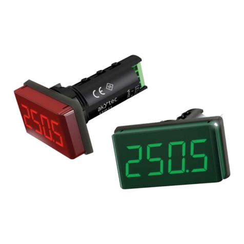
A 4-digit, 7-segment LED display (red) with 14 mm character height is located on the front of
the device for displaying the measured values and error messages. The terminals are
located on the rear side of the device. The maximum wire size is 0.75 mm2.
Fig. 4.1 Fig. 4.2
5 Installation
The device is designed for switch panel mounting in a borehole of Ø22.5 mm (see Annex A
for dimensional drawings).
Carefully position the supplied gasket on the display rear surface. Insert the cylindrical part
of the device into the borehole and tighten the nut from the rear side of the switch panel.

akYtec GmbH · Vahrenwalder Str. 269 A · 30179 Hannover · Germany Tel.: +49 (0) 511 16 59 672-0 · www.akytec.de
4
Fig. 5.1 Mounting
6 Electrical wiring
DANGER
Dangerous voltage
Even if the auxiliary voltage is switched off, dangerous voltage up to 400 V may
exist!
Make sure that the device is fully disconnected from auxiliary power and
measuring voltage before starting any commissioning or repair work.
Connect the power supply only after the wiring has been completed.
– The voltmeter must be provided with its own fuse or a circuit breaker.
– 300 mA fuse or circuit breaker is recommended.
– Connect the leads of the supply and measuring voltage according to Fig. 3 to the device.
– The maximum wire size is 0.75 mm².
Fig. 6.1
7 Operation
After the power supply is switched on the following values will be displayed successively:
−Firmware checksum (8 digits, ticker-tape)
−Firmware version (Ux.xx)
−Measuring voltage
If the measuring voltage is less than 5 V the error message 0000 will be displayed.
If the measuring voltage is greater than 400 V the error message HHHH will be displayed.
If the measuring voltage is not displayed correctly, check the connecting cable and the
polarity.
8 Maintenance
The maintenance includes:
– cleaning the housing and the terminals from dust, dirt and debris
– checking the fastening of the device
– checking the wiring (connecting leads, fastenings, mechanical damage)
The device should be cleaned with a damp cloth only. No abrasives or solvent-containing
cleaners may be used.

akYtec GmbH · Vahrenwalder Str. 269 A · 30179 Hannover · Germany Tel.: +49 (0) 511 16 59 672-0 · www.akytec.de
5
The safety guidelines in Section 1 must be observed when performing maintenance.
9 Transportation and storage
Pack the device in such a way as to protect it reliably against impact for storage and
transportation. The original packaging provides optimum protection.
If the device is not taken immediately after delivery into operation, it must be carefully stored
at a protected location. The device should not be stored in an atmosphere with chemically
active substances.
Permitted storage temperature: -25…+55 °C
►
NOTICE
The device may have been damaged during transportation.
Check the device for transport damage and completeness!
Report the transport damage immediately to the shipper and akYtec GmbH!
10 Scope of delivery
−INS-F1 1
−Gasket 1
−Mounting nut 1
−User guide 1
Appendix A. Dimensions
Fig. A1 Fig. A2
To prevent the device spinning, the borehole in the front panel must correspond to the
dimensions in Fig. A.2.
Ø 22,5
20,8
М22
Table of contents
Other Akytec Measuring Instrument manuals
Popular Measuring Instrument manuals by other brands

TSI Instruments
TSI Instruments DP-CALC 5825 Operation and service manual

Velleman-Kit
Velleman-Kit K4305 quick start guide

Orion
Orion 14710 user manual

Bosch
Bosch PDO 6 operating instructions

ICP DAS USA
ICP DAS USA DL-100TM-ZT quick start

MONARCH INSTRUMENT
MONARCH INSTRUMENT Nova-Pro 100 instruction manual