manuals.online logo
Brands
  1. Home
  2. •
  3. Brands
  4. •
  5. Akytec
  6. •
  7. Measuring Instrument
  8. •
  9. Akytec ITP11 W Series User manual

Akytec ITP11 W Series User manual

ITP11-W
Ordering code
Functions
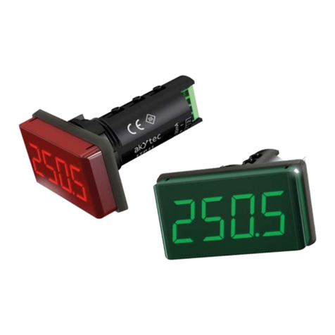
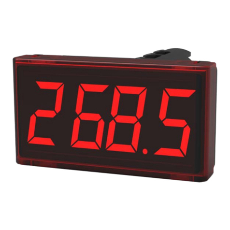
The ITP11 is a universally applicable digital display unit. It is designed to be connected to any device
with a 4-20 mA output (current loop).
The device has the following functions:
–Process value is displayed in accordance with the set limit values and the decimal point position
–Display range -999…9999
–Filter for damping the signal fluctuations with an adjustable time constant
–Switching between linear and square root (for specialtransmitters)
–Displaying error message when exceeding the measuring limit
–Protection against unauthorized access
Specifications
Supply current
from current loop
Voltage drop
≤10 V *
Input signal
4-20 mA
Measuring range
3.8…22.5 mA
Accuracy
0.2% + 1 digit
Sampling rate (without damping)
1 reading / s
Ambient temperature
-40…+80 °C
Application class according to IEC 61140
III
IP Code
IP65
Dimensions (without carrier and cable gland)
70 x 50 x 28 mm
Weight
approx. 150 g
Mounting
DIN rail, wall, tube
Cable clamping range
Ø 3…6 mm
►
NOTICE
*Power supply must be provided not only for ITP11, but also for a sensor. The device voltage drop of 10 V has to be taken into
account.
Fig. 1
Installation
1. Remove the slide covers (1) in the direction of the arrows (Fig. 2).
2. Unscrew the screws (3) and remove the front panel (2).
3. Screw the cable glands (included) with the sealing rings (5) tightly into
the enclosure, so as to guarantee the IP65 protection.
4. Not used cable entry has to be locked with the blind cap (included).
5. Feed the cable through the cable gland into the enclosure.
6. Connect the wire ends according to the wiring diagrams (Fig. 4 - 6)
and tighten the cap nut (6).
7. Put the front panel (2) back and fasten it with the screws (3).
Fig. 2
Fig. 3
8. To mount the device on DIN rail attach the carrier (7) to the device
using the two screws (4) and snap the device onto the DIN rail.
9. To mount the device on a tube attach the carrier (7) to the tube using
two 6 mm wide cable ties (Fig. 3), then attach the device to the carrier
(7) using the screws (4).
10. To mount the device on the wall use the two holes for the screws (4)
11. Snap the two slide covers (1) onto the front panel (2).
ITP11-W_0217_EN
© All rights reserved. Subject to technical changes and misprints.
akYtec GmbH · Vahrenwalder Str. 269 A · 30179 Hannover · Germany
Tel.: +49 (0) 511 16 59 672-0 · www.akytec.de
Display colour:
R - red
G - green
Enclosure type:
W - universal mounting
Wiring diagrams
Fig. 4 Connection from the right
Fig. 5 Connection from the left
Fig. 6 Two side connection
(terminals 1, 4 or 2, 3)
Wire connection
Fig. 7 Wire preparation
Fit the stranded wire with a wire end ferrules
Fig. 8 Connecting the wire to the
terminal
Fig. 9 Disconnecting the wire
Press the actuation lever and the contact is opened
Programming
Operation
Fig. 10 Flowchart
Conversion functions
linear function
 
LodiHidi
I
LodiT..
164
.


square root function
 
LodiHidi
I
LodiT..
164
.


where
T–displayed value corresponding to input signal I, mА
di.Lo –Lower limit, corresponds to 4 mA
di.Hi –Upper limit, corresponds to 20 mA
Display messages
Display
Cause
Input current lower than 3.8 mA
Input current higher than 22.5 mA
« »
Upper menu line has been reached
« »
Lower menu line has been reached
not lit
No input signal
Polarity reversal
With particular setting parameters the device cannot actually
display the necessary 5 figures due to the restriction to four
segments.
Example
The parameters are configured as follows:
di.Lo: -999 4 mA
di.Hi: 9999 20 mA
With an input measured current of 20.8 mA the correct display
should be “10548”. Due to the restriction to four segments, the
first character is removed and the display is “0548”.
Maintenance
The maintenance includes:
–cleaning the housing and the terminals from dust, dirt and debris
–checking the fastening of the device
–checking the wiring (connecting leads, fastenings, mechanical damage)
The device should be cleaned with a damp cloth only. No abrasives or solvent-containing cleaners may be used.
ITP11-W_0129_EN
© All rights reserved. Subject to technical changes and misprints.
akYtec GmbH · Vahrenwalder Str. 269 A · 30179 Hannover · Germany
Tel.: +49 (0) 511 16 59 672-0 · www.akytec.de

This manual suits for next models

2

Other Akytec Measuring Instrument manuals

Akytec INS-F1 User manual

Akytec

Akytec INS-F1 User manual

Akytec ITP15 User manual

Akytec

Akytec ITP15 User manual

Akytec ITP14 User manual

Akytec

Akytec ITP14 User manual

Akytec ITP11 User manual

Akytec

Akytec ITP11 User manual

Popular Measuring Instrument manuals by other brands

Tru-Test EC-20 user guide

Tru-Test

Tru-Test EC-20 user guide

UEi UTL2002 instruction manual

UEi

UEi UTL2002 instruction manual

ACOEM Meax DU 01 user manual

ACOEM

ACOEM Meax DU 01 user manual

Rigol PCA1030 user guide

Rigol

Rigol PCA1030 user guide

PCB Piezotronics M353B18 Installation and operating manual

PCB Piezotronics

PCB Piezotronics M353B18 Installation and operating manual

Hedue M420 manual

Hedue

Hedue M420 manual

SENSIT Technologies Trak-It IIIa Quick start instructions

SENSIT Technologies

SENSIT Technologies Trak-It IIIa Quick start instructions

Beckman Coulter IMMAGE 800 Operation manual

Beckman Coulter

Beckman Coulter IMMAGE 800 Operation manual

netAlly AirCheck G3 quick start guide

netAlly

netAlly AirCheck G3 quick start guide

Pittsburgh 63586 Owner's manual & safety instructions

Pittsburgh

Pittsburgh 63586 Owner's manual & safety instructions

Aktakom ATE-6008 user manual

Aktakom

Aktakom ATE-6008 user manual

Baumer HUBNER POG 10 + ESL Mounting and operating instructions

Baumer

Baumer HUBNER POG 10 + ESL Mounting and operating instructions

TPI 510 user manual

TPI

TPI 510 user manual

TESTO 206 instruction manual

TESTO

TESTO 206 instruction manual

CPC 210-2006 installation instructions

CPC

CPC 210-2006 installation instructions

M-system R9EWTU instruction manual

M-system

M-system R9EWTU instruction manual

Olympus STM7-AF instructions

Olympus

Olympus STM7-AF instructions

HunterLab ColorFlex 13-1 user manual

HunterLab

HunterLab ColorFlex 13-1 user manual

manuals.online logo
manuals.online logoBrands
  • About & Mission
  • Contact us
  • Privacy Policy
  • Terms and Conditions

Copyright 2025 Manuals.Online. All Rights Reserved.