AL-KO AIRCABINET User manual

COMPACT AIR HANDLING UNIT
EN
INSTALLATION AND OPERATING MANUAL
AL-KO AIRCABINET®

Translation of the original operating manual
2
AL-KO AIRCABINET®
Legal
AL-KO THERM GMBH
Hauptstraße 248 - 250
D-89343 Jettingen-Scheppach
Germany
Phone: +49 8225 39 - 0
Fax: +49 8225 39 - 2113
E-mail: [email protected]
Revision history
Version Description Date
1.0 3420877/February 2021 26/02/2021

Subject to changes in line with technical progress. 3
3420878
Table of contents
1 About this manual..........................................................................................5
1.1 Explanation of symbols ..............................................................................................................................5
1.1.1 Safety instructions......................................................................................................................................5
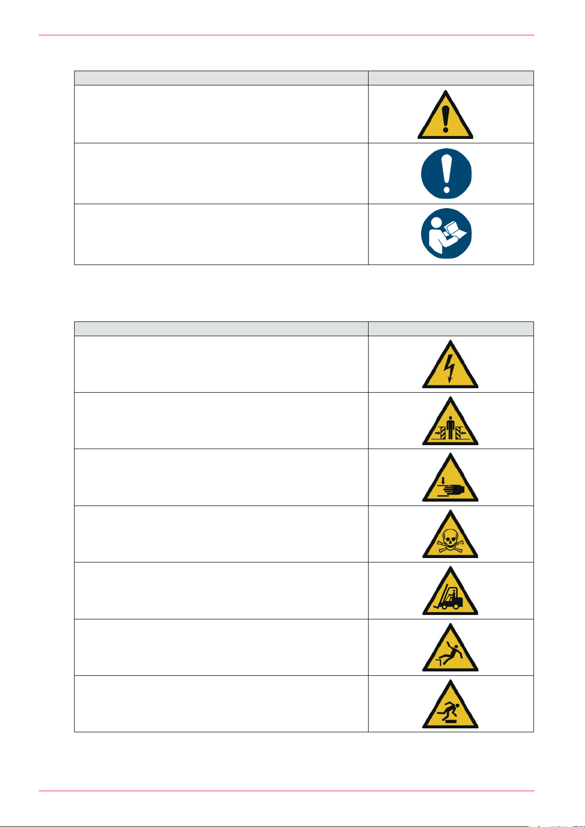
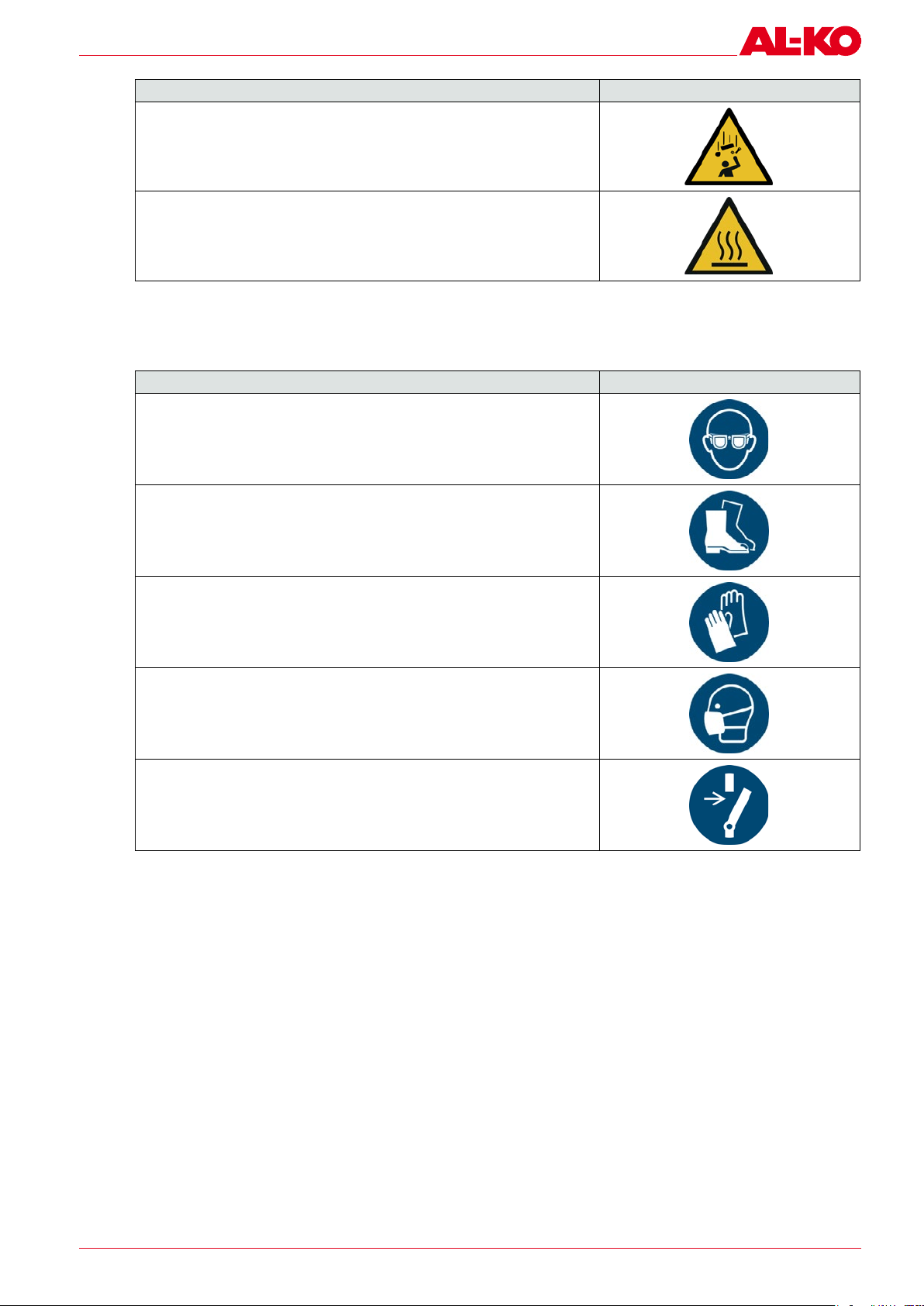
1.2 Safety symbols...........................................................................................................................................6
1.2.1 Abbreviations..............................................................................................................................................7
1.3 Legal notices .............................................................................................................................................. 7
2 Safety instructions .........................................................................................8
2.1 General safety instructions .........................................................................................................................8
2.2 Specicsafetyinstructions.......................................................................................................................11
2.2.1 Warnings for cleaning work......................................................................................................................11
2.2.3 Intended use.............................................................................................................................................11
2.2.4 Foreseeable misuse .................................................................................................................................. 12
3 Product description ...................................................................................... 13
3.1 Functional description .............................................................................................................................. 13
3.1.1 Overview...................................................................................................................................................13
3.1.2 Functional sequence.................................................................................................................................14
3.1.3 Unit modules ...........................................................................................................................................14
3.1.3.1 Basic unit..................................................................................................................................................14
3.1.3.2 Silencer module........................................................................................................................................15
3.1.3.3 Air distributor module ..............................................................................................................................15
3.1.4 Electrical connections...............................................................................................................................15
3.1.5 Presence switch ....................................................................................................................................... 15
3.1.6 Control unit...............................................................................................................................................16
3.1.7 Remote access portal ...............................................................................................................................17
3.1.8 HMI for web..............................................................................................................................................17
3.1.9 Network connection..................................................................................................................................17
3.1.10 Connection for building management system ..........................................................................................17
3.1.11 Airows ...................................................................................................................................................18
3.1.12 Cooling .....................................................................................................................................................19
3.1.13 Combination exterior wall diffuser............................................................................................................19
3.1.14 Piping .......................................................................................................................................................20
3.1.15 Technical data........................................................................................................................................... 20
3.2 Type plat of the AL-KOAIRCABINET®compact air handling unit..............................................................21
4 Delivery, transport, storage ............................................................................ 22
4.1 Delivery ....................................................................................................................................................22
4.1.1 Scope of supply........................................................................................................................................22
4.1.2 Transport damage.....................................................................................................................................22
4.2 Transport ..................................................................................................................................................23
4.2.1 Safety .......................................................................................................................................................23
4.2.2 Transport under normal conditions ..........................................................................................................24
4.2.3 Transport under aggravated conditions ....................................................................................................24
4.2.4 Transport with pallet truck........................................................................................................................24
4.2.5 Transport from the delivery to the installation site....................................................................................24
4.3 Storage prior to installation ......................................................................................................................25
4.4 Disposal of packaging ..............................................................................................................................25
5 Installation ................................................................................................ 26
5.1 Safety .......................................................................................................................................................26
5.2 Preparing the compact air handling unit for installation ...........................................................................27
Table of contents

Translation of the original operating manual
4
AL-KO AIRCABINET®
5.3 Setting up and installing the unit ..............................................................................................................27
5.4 Connecting the unit to the mains power supply........................................................................................28
5.5 Installing the combination exterior wall diffuser.......................................................................................29
5.5.1 Safety .......................................................................................................................................................29
5.5.2 Overview...................................................................................................................................................30
5.5.3 Creating and inserting a sandwich window element .................................................................................30
5.5.4 Installing a combination exterior wall diffuser ..........................................................................................31
5.6 Installing the piping..................................................................................................................................31
5.6.1 Safety .......................................................................................................................................................31
5.6.2 Overview...................................................................................................................................................32
5.6.3 Installing the piping..................................................................................................................................32
6 Commissioning........................................................................................... 33
6.1 Safety .......................................................................................................................................................33
6.2 Switching the unit on and off....................................................................................................................34
6.2.1 Safety .......................................................................................................................................................34
6.2.2 Overview...................................................................................................................................................34
6.2.3 Switching on the unit................................................................................................................................34
6.2.4 Switching off the unit ...............................................................................................................................35
7 Servicing and maintenance ............................................................................ 36
7.1 Safety .......................................................................................................................................................36
7.2 Maintenance schedule .............................................................................................................................. 37
7.3 Carryoutlterchange ..............................................................................................................................39
7.3.1 Safety .......................................................................................................................................................39
7.3.2 Overview...................................................................................................................................................40
7.3.3 Filter change indicator ..............................................................................................................................40
7.3.3.1 Carryoutlterchange ..............................................................................................................................41
7.4 Resetting the safety temperature limiter...................................................................................................42
7.4.1 Safety .......................................................................................................................................................42
7.4.2 Overview...................................................................................................................................................42
7.4.3 Resetting the safety temperature limiter...................................................................................................43
7.5 Circuit diagrams .......................................................................................................................................43
8 Integrated control ........................................................................................ 44
9 Help in the event of malfunctions ..................................................................... 47
9.1 Safety .......................................................................................................................................................47
9.2 Possible malfunctions .............................................................................................................................. 48
9.3 Contacts ...................................................................................................................................................49
10 Spare parts................................................................................................ 50
10.1 Spare part list ...........................................................................................................................................50
10.2 Proof of delivery .......................................................................................................................................50
11 Disposal ................................................................................................... 51
12 EC Declaration of Conformity in accordance with 2006/42/EC .................................... 52

Subject to changes in line with technical progress. 5
3420878
About this manual
1 About this manual
This Installation and Operating Manual applies to the AL-KOAIRCABINET®unit.
The German version is the original text of the Installation and Operating Manual. All further language versions are
translations of the original Installation and Operating Manual.
Read this Installation and Operating Manual carefully before installation, commissioning and maintenance. This is
the prerequisite for safe work and trouble-free handling.
Observe the safety instructions and warnings in this documentation and on the product.
This documentation is a permanent part of the described product, and must be handed over to the buyer if the prod-
uct is sold.
1.1 Explanation of symbols
1.1.1 Safety instructions
DANGER
This signal word is used to indicate an immediate dangerous situation which, if not avoided,
will result in death or severe injury.
WARNING
This signal word is used to indicate a potentially dangerous situation which, if not avoided,
could result in death or severe injury.
CAUTION
This signal word is used to indicate a potentially dangerous situation which, if not avoided,
could result in minor injury.
ATTENTION
This signal word is used to indicate a potential risk of property damage.
NOTE
Special instructions for ease of understanding and handling.

Translation of the original operating manual
6
AL-KO AIRCABINET®
1.2 Safety symbols
Meaning Symbol
GENERAL DANGER SYMBOL
If the required safety instructions are not observed, this can lead to death, severe
injuries and serious property damage.
IMPORTANT NOTE
If this notice is not observed, problems can arise with the unit.
OBSERVE THE INSTALLATION AND OPERATING MANUAL
If the notices in the Installation and Operating Manual are not observed, problems
can arise with the unit.
Warning symbol
ThewarningsymbolsusedinthisInstallationandOperatingManualdrawattentiontospecichazards.
Meaning Warning symbol
Warning of electric shock hazard
If the necessary safety instructions are not observed, this can lead to
severeinjuryorevendeathduetohazardouselectricshock.
Warning of crushing hazard
If the necessary safety instructions are not observed, this can lead to
severe injury or even death due to crushing.
Warning of hand injury risk
If the necessary safety instructions are not observed, this can lead to
severe injury or even death.
Warning of substances hazardous to health
If the necessary safety instructions are not observed, this can lead to
severe injury or even death.
Warning of hazards due to industrial trucks
If the necessary safety instructions are not observed, this can lead to
severe injury or even death.
Warning of falling from heights
If the necessary safety instructions are not observed, this can lead to
severe injury or even death.
Warning of obstacles on the oor
If the necessary safety instructions are not observed, this can lead to
severe injury or even death.

Subject to changes in line with technical progress. 7
3420878
About this manual
Meaning Warning symbol
Warning of falling objects
If the necessary safety instructions are not observed, this can lead to
severe injury or even death.
Warning of hot surfaces
If the necessary safety instructions are not observed, this can lead to
severe injury or even death.
Instruction symbol
The instruction symbols used in this Installation and Operating Manual draw attention to instructions to be observed.
Meaning Instruction symbol
Wear eye protection
If eye protection is not worn, injuries may be caused to the eyes.
Wear foot protection
If foot protection is not worn, injuries may be caused to the feet.
Wear hand protection
If hand protection is not worn, injuries may be caused to the hands.
Wear breathing masks
If respiratory protection is not worn, poisoning and chemical burns to the
lungs may occur.
Isolate before maintenance or repair
Failure to disconnect the unit from all energy sources before starting maintenance
or repair work can result in serious injuries.
1.2.1 Abbreviations
PPE – Personal Protective Equipment: for example, cut-proof gloves, safety goggles, helmet, working gloves, helmet,
mask
1.3 Legal notices
Allspecieddataservesolelytodescribetheproduct.Nostatementonaspeciccharacteristicorsuitabilityforaspe-
cicpurposecanbederivedfromthesedata.Thedatadonotexempttheuserfromhisownjudgementandchecks.

Translation of the original operating manual
8
AL-KO AIRCABINET®
2 Safety instructions
2.1 General safety instructions
2.1.1 Warnings
WARNING
Risk of serious injury or even death due to working without personal protective equip-
ment!
Working on the AL-KOAIRCABINET®without personal protective equipment (PPE) can result
in serious injuries or even death.
Observe the safety instructions in this Installation and Operating Manual.
Wear your PPE during all work on the unit.
Use further protective equipment according to the work to be carried out.
WARNING
Risk of serious injuries or death!
Working on the AL-KOAIRCABINET®can result in serious injuries or death.
Haverepair,maintenanceandserviceworkcarriedoutonlybyqualiedstaff.
Disconnect the unit from the mains power supply and secure it to prevent restart before
starting repair or maintenance work.
Avoidnakedamesandsparksintheintakeareaoftheunit.
Observe the working instructions and this Installation and Operating Manual.
Work carefully at all times.
Wear your PPE during all work on the unit.
WARNING
Risk of injury from unauthorised opening.
Keep the maintenance panel and the maintenance doors closed during operation.
Never open the unit during operation.
Theunitmayonlybeopenedbyqualiedstaffortrainedpersons.
2.1.2 Children and persons with limited capabilities
This unit may be operated by children aged eight years and older and by persons with limited phys-
ical, sensory or mental capabilities or lacking experience and/or knowledge as long as they are su-
pervised or have been instructed in the safe use of the unit and are aware of the resulting dangers.
Children must not be allowed to play with the unit. Children may not clean or perform user mainte-
nance on the pump without supervision.
Persons with very severe and complex limitations may have requirements going beyond the instruc-
tions given here.

Subject to changes in line with technical progress. 9
3420878
Safety instructions
2.1.3 Improper use and operation
ObservethesafetyinstructionsinthisInstallationandOperatingManualinordertoavoidinjury,re
and other dangers caused by improper use and operation of the unit:
The version and construction of the AL-KOAIRCABINET®unit complies with the standards listed
in the Declaration of Conformity.
If installation is performed contrary to our regulations, and the defect/damage which has oc-
curredisattributabletoimpropermodication,processingoranyothertreatment,alldamage
compensation or warranty claims are ruled out. The orderer must prove that improper installa-
tion did not cause the defect which has occurred.
Safety and monitoring equipment must not be removed, bridged or disabled in any other way.
All authorised persons must have read and understood the Installation and Operating Manual in
full before starting work on the unit and must observe them at all times!
Inorderavoidhazardsduringoperation,allcompany,operatingandworkinginstructionsofthe
user apply in addition to this Installation and Operating Manual.
2.1.4 Safety instructions for operation
TheunitmayonlybeoperatedintheperformancerangespeciedintheAL-KOTHERMGmbH
technical documents.
The AL-KO AIRCABINET®compact air handling unit must be installed correctly and used in
strict compliance with our Installation and Operating Manual.
Theunitmayonlybeoperatedfullyassembledandttedwitheffectivecontactprotection.
Theunitmayonlybeoperatedinatechnicallyawlesscondition.Malfunctionsanddamagethat
canaffectsafetymustbeimmediatelyandprofessionallyrectied.
The version and construction of the AL-KOAIRCABINET®compact air handling unit complies
with the standards listed in the Declaration of Conformity or Incorporation. All electrical parts are
protectedbyxed,securelyfastenedguardsthatcanonlyberemovedusingtools.
Avoid sparking in the vicinity of the AL-KOAIRCABINET®compact air handling unit.

Translation of the original operating manual
10
AL-KO AIRCABINET®
2.1.5 Safety instructions for maintenance
Replace damaged and worn components only with original spare parts.
Always disconnect the unit plug before starting repair and maintenance work.
General maintenance instructions in the Installation and Operating Manual of the AL-KO THERM
GmbH must be observed under all circumstances.
Observe the delay time of the fan. Wait at least three minutes for the fan impeller to come to a
standstill before opening the maintenance panel and the maintenance door.
2.1.6 Personal safety instructions
The AL-KOAIRCABINET® compact air handling unit may only be operated by persons trained in
its use and expressly authorised to do so.
The wearing of PPE is necessary when working on the AL-KOAIRCABINET®compact air han-
dling unit.
The Installation and Operating Manual must be available at a suitable place in the unit operating
location.
2.1.7 Residual dangers
Theunitmayposehazardsifitisnotoperatedbytrainedpersonneland/orisoperatedimproperlyor
not according to its intended use.
Residualdangersarepotentialhazardsthatarenotimmediatelyapparent,suchas:
Injuries due to failure to observe the safety instructions, standards, directives or regulations.
Injuries caused by uncoordinated work.
Injuries or death from electric shock due to working on cables with damaged insulation and de-
fective connections.
Riskofrehazardduetodamagedfanparts,e.g.hot-runningbearings.
Injuries caused by working on the fan before it has come to a standstill.
Injuries caused by pinching or crushing and collisions during transport, unpacking and setup of
the unit.
Tipping of the unit due to installation on uneven or loose ground.
Risk of tripping and falling due to improper routing of the electrical connecting lead.
Healthhazardsduetopoorhygiene,suchasfailuretochangeltersatregularintervals.
Hazardsduetomisconductresultingfromfailuretoobservethesafetyinstructions,standards
and regulations.

Subject to changes in line with technical progress. 11
3420878
Safety instructions
2.2 Specic safety instructions
2.2.1 Warnings for cleaning work
WARNING
Risk of injury due to collisions, cutting, pinching and crushing.
There is a risk of injury to hands and arms during cleaning work.
Work carefully at all times.
Wear your PPE (cut-proof gloves, safety goggles, safety shoes).
WARNING
Health hazards due to contact with media.
Thereisariskofhealthhazardsduringcleaningworkduetoskincontactwithcontaminated
impurities and liquids and inhalation of vapours.
Minimise the risk of contamination by observing the maintenance intervals.
Use food-safe and paint-compatible disinfectants and cleaning agents.
Test the paint compatibility on an inconspicuous area of the housing surface.
Use only approved containers.
Ensure an adequate outdoor air supply.
Wear your PPE (cut-proof gloves, safety goggles, breathing mask).
Observethesafetydatasheetandthehazardoussubstancesregulationsforthecleaning
agents used.
2.2.2 Training
The owner/operator of the AL-KOAIRCABINET®compact air handling unit must brief his personnel on the following
subjects at regular intervals:
Compliance with the Installation and Operating Manual and the statutory regulations.
Intended used of the unit.
Observance of all company, operating and working instructions at the owner’s/operator's installation site.
Response to faults.
2.2.3 Intended use
The AL-KOAIRCABINET®compact air handling unit is intended exclusively for the replacement of used and possibly
virus-contaminated atmospheric air with outdoor air in heavily frequented spaces. The unit reduces the risk of infection
by lowering the dust content, aerosol concentrations and other contaminants in the air. The unit is suitable for operation
in the temperature range from -20°C to +40°C. Deviating ranges of application must be agreed with the manufacturer.
The unit may only be used for air exchange in interiors, such as:
Classrooms in schools
Day care centres
Conference rooms
Cafeterias
Lecture rooms
Meeting rooms

Translation of the original operating manual
12
AL-KO AIRCABINET®
The risk is borne solely by the user. Furthermore, the intended use also means compliance with the operating and main-
tenance conditions listed in this Installation and Operating Manual (see sections "6 Commissioning" on page 33 and
"7 Servicing and maintenance" on page 36).
Operate the unit only when it is fully assembled.
Set up the unit on level ground.
Protect the unit from moisture.
Use only original spare parts from AL-KO THERM GmbH.
Children and people who are not familiar with the unit may not use it.
Observeallaccidentpreventionandreprotectionregulations.
2.2.4 Foreseeable misuse
The AL-KOAIRCABINET®compactairhandlingunitmayonlybeoperatedwithinthescopeofthetechnicaldataspecied
by AL-KO THERM GmbH. Any other use or use beyond that described in section "2.2.3 Intended use" on page 11 is
regarded as being not in accordance with the intended use. The manufacturer cannot be held liable for damage resulting
from this. Possible misuse includes:
Horizontalsetupoftheunitnotpresent.
Storage of objects on the unit.
Conveying media with non-permissibly high or low temperatures.
Conveying aggressive media or media with a high dust content.
Installation and operation in an environment with aggressive media (e.g. sea air) or media with a high dust content
(desert).
Setup and operation outdoors.
Operationwithoutoutdoorairlterandexhaustairlter.
Use in a potentially explosive atmosphere.
Failure to observe the static limits (customer supplied).

Subject to changes in line with technical progress. 13
3420878
Product description
3 Product description
The AL-KOAIRCABINET® compact air handling unit is used for the continuous supply of outdoor air, especially in the
event of poor ventilation options. With extremely quiet continuous operation, the complete replacement of used and
possiblyvirus-contaminatedroomairwithlteredoutsideairbylteredoutdoorairiscarriedout.Theunitrecovers
more than 80% of the heat energy from the used room air. The CO2content of the room air is constantly maintained at
theprescribedvalueof<1000ppm,whichincreasestheabilitytoconcentrateofpersonspresent.Theltrationmeets
the highest hygiene standards.
The exact type designation can be found on the type plate attached to the housing. When ordering replacement parts
or in case of other queries, please specify the type designation of the AL-KOAIRCABINET®unit, the year of man-
ufacture and the serial number (see chapter "3.2TypeplatoftheAL-KOAIRCABINET®compactairhandlingunit"
on page 21).
The unit is suitable for operation in the temperature range from -20°C to +40°C.
The unit construction consists of three components which are assembled at the installation site.
The unit is available only for indoor installation.
3.1 Functional description
3.1.1 Overview
LR
2 2
3 3
4 4
24
24 24
1
3
24
5
6
7
8
9
10
11
12
13
14
15
1719 18
16
16
C
21
20
16
26
B
A
23
22
25
26
27
28

Translation of the original operating manual
14
AL-KO AIRCABINET®
A air distributor module 13 Exhaustairlter
B Silencer module 14 LAN connection
C Basic unit 15 Cable bushing for connection cable with 230 V safety
plug
LAirdistributormodule,supplyair/exhaustairttings,
left-hand side
16 Foot
RAirdistributormodule,supplyair/exhaustairttings,
right-hand side
17 CO2sensor, exhaust air
1 Shut-off damper with stepper motor 18 Heat recovery
2Exhaustairtting 19 Drip pan
3Outdoorairtting 20 Electric air heater with safety temperature limiter
4 Exhaust air grille (exhaust air opening) 21 Exhaust air / supply air partition plate
5 Sound absorber 22 Supply air fan
6Outdoorairlter 23 Exhaust air fan
7 Electrical control cabinet 24 Supplyairtting
8 Control unit connection socket 25 Maintenance panel
9 LED status display 26 Maintenance door
10 Main switch 27 Maintenance door turn lock
11 Bypass damper (thermal bypass) 28 Maintenance panel turn lock
12 Filter pressure monitoring and heat recovery
3.1.2 Functional sequence
The compact air handling unit controls two parallel and permanent processes for the supply of outdoor air during its
operation:Theunitdrawsinroomair,ltersit,extractsheatfromitifnecessaryandpassesitoutintotheopenasex-
haustair.Atthesametime,outsideairisdrawnin,ltered,heatedifnecessarybyheatrecoverywithoptionalauxiliary
heating and discharged to the interior.
3.1.3 Unit modules
The AL-KOAIRCABINET®compact air handling unit consists of three modules which are assembled at the installation
site of the unit:
Basic unit
Silencer module
Air distributor module
3.1.3.1 Basic unit
Thebasicunit(C)containsthecomponentsforlteringtheairows,theheatrecovery(18)withthermalbypass(11),an
electricairheater(20)forairheating,thelow-noiseECfans(22),(23)forconductingthetwoairows,theCO2sensor
for the exhaust air (17) and the pressure monitoring (12). In addition, the electrical control cabinet (7) in the basic unit.
Four feet (16), on which the mounted compact air handling unit rests, are mounted on the base.
The electric air heater (20) is equipped with a safety temperature limiter which interrupts the circuit if the surface tem-
perature of the electric air heater (20) is too high. The safety temperature limiter must be reset manually after automatic
triggering.
Twoltersareusedtocleantheairowsintheunit:Theexhaustairlter(13)cleanstheexhaustairfromthespace
andprotectstheunitfromcontamination.Theoutdoorairlter(6)cleansthefreshoutdoorairandmeetsthehighest
hygiene standards.
The switch cabinet records the control of the unit on the basis of Siemens Climatix and its electronics (see chapter
"Control unit" on page 16).
A countercurrent plate heat exchanger is used for heat recovery (18) from the exhaust air and to heat the outside air;
the electric air heater (20) is switched on by the control unit if necessary to further heat the fresh outside air before it is
released into the space. The bypass damper (11), which is driven by a servomotor and monitored by the control, makes
it possible to bypass the heat recovery, for example on days with high outside temperatures.

Subject to changes in line with technical progress. 15
3420878
Product description
At the bottom of the basic unit there is a drip pan (19) for any condensation water.
The unit is accessible via two maintenance doors (26).
3.1.3.2 Silencer module
In the silencer module (B) of the compact air handling unit there are four sound absorbers (5) separated by partition
wallsfornoisereductioninallairows.Formaintenancepurposes,themaintenancepanel(25)andthesoundabsorbers
(5) can be removed.
3.1.3.3 Air distributor module
Theairdistributormodule(A)containsthreeroundpipettings:Theexhaustairtting(2)fordischargingusedroomair
intotheopenair,theoutdoorairtting(3)forreceivingfreshoutdoorair,andthesupplyairtting(24)fordischarging
cleaned and temperated supply air into the space. Furthermore, the air distributor module contains the exhaust air grille
(4), which is located below the exhaust air opening, for receiving the room air (exhaust air) being replaced.
The air paths for outside air and exhaust air can be closed in the switched-off state of the compact air handling unit by
means of shut-off dampers (1) controlled by an electric servomotor. This prevents uncontrolled air circulation between
the inside and outside.
Depending on the requirements for the spatial situation at the place of operation, the air distributor module can be
conguredwiththeexhaustairttingandtheexhaustairttingontheleft-handside(L)orontheright-handside(R).
3.1.4 Electrical connections
The permanently installed three metre long connection cable with 230 V safety plug is led out via the cable bushing (15)
on the right-hand outside of the compact air handling unit. The power supply to the compact air handling unit is provided
by a 16 A domestic power supply. Alternatively, a permanent connection provided on site can provide the power supply.
On the right side of the basic module there is an LED (9) which signals the unit condition:
LED off: Unit switched off.
LED green: Unit in operation.
LED red: A malfunction has occurred. The control unit must be connected and the malfunction determined. Or main-
tenance work is currently being carried out on the unit.
Furthermore, as seen from the operating side, the main switch (10) and a LAN connection (14) are located on the right-
hand side of the unit; this can optionally be used for connection to a local network for setting up remote maintenance.
The control unit is plugged into the connection socket (8) using a spiral cable.
An optional presence switch can also be operated. The connection cable must also be passed through the cable bushing
(15)andwiredtotheswitchboxbyaqualiedelectrician.
3.1.5 Presence switch
The optional presence switch is to be attached to the ceiling in the middle of the space to be ventilated and connected to
the compact air handling unit via a data cable. The presence switch detects whether or not there are persons in the room
and switches the unit on or off accordingly.
When the compact air handling unit is active, the CO2value is measured and the air volume is increased to the maximum
volumeowwhenthesetlimitvalueisreached.
If the room is not occupied, a delay time of 30 minutes ensures that break times are covered.

Translation of the original operating manual
16
AL-KO AIRCABINET®
3.1.6 Control unit
NOTE
For detailed information on the control unit and its handling, refer to the operating manual /
functional description for the Art Tech Level II control.
Monitoring and setting of the control of the compact air handling unit is carried out via a mobile control unit with control
knob, malfunction indicator lamp and display.
321
456
1 Control unit 4 OK button
2INFO button with integrated LED 5 ESC jump back button
3 Display 6 ALARM button with integrated LED
The control unit (1) has magnetic holders on its rear side for attachment at any desired point on the outer skin of the de-
vice, preferably in the area of the maintenance panel. The unit is connected to the control with a spiral cable via a network
socket located above the main switch. An optional 15 m long extension cable is available from AL-KO THERM GmbH. By
opening the closing clip on the underside of the control unit, the control unit can be opened and the spiral cable can be
replaced with a longer network cable.
Alternatively, a wall-mounting bracket with three screw connections is possible; for this purpose, the unit must be
opened in the unplugged state on its rear side.
Pressing the INFO button (2) calls up the start page on the display. The integrated LED signals the status of the compact
air handling unit:
LED off: Unit ready for operation or unplugged
LED green: Unit in operation
LED red: There is a malfunction.
The display (3) shows operating conditions, settings as well as actual and setpoint values.
The knob (4) provides the following settings:
Clockwise rotation corresponds to scrolling up the display menu or increasing a setting value.
Turning anti-clockwise corresponds to scrolling down the menu or decreasing a setting value.
Pressingtherotaryknoballowsyoutoconrmanewsettingorjumptoamenuitemoramenupage.
The ESC button (5) allows you to jump back to the previous menu page in the user interface.
Thealarmbutton(6)callsupthealarmpages.TheintegratedalarmLEDashesredwhenanalarmispresent.Inthe
fault-free state, the alarm LED is off.

Subject to changes in line with technical progress. 17
3420878
Product description
The compact air handling unit can also be operated with the control unit removed in a time program or via a presence
detector.
In both cases, malfunctions are signalled by the red LED status display installed on the air handling unit. However, to be
able to determine the corresponding causes of malfunctions, the control unit must be connected to a display.
3.1.7 Remote access portal
The compact air handling unit can also be optionally monitored and set remotely via the AL-KO THERM GmbH remote
access portal https://remote.al-ko.com/ for example, a PC, a notebook or a tablet.
In addition to the digital twin of the mobile control unit, the AL-KO THERM GmbH remote access portal offers functions
suchashistoricalrecordingofalarmsanddatapoints,aplantdiagramandautomaticnoticationbye-mailforalarms.
3.1.8 HMI for web
With the HMI for web the entire installation can be fully set and commissioned according to the logged-in password
level. HMI for web is the standard equipment of the control. The function can be accessed via the network connection
of the control via an on-site terminal (PC, notebook, table) via web browser. Menu structure and password level are
identical to the control unit.
3.1.9 Network connection
Both the AL-KO THERM GmbH remote access portal and HMI for web are connected to the compact air handling unit via
a network connection. This is located above the main switch.
3.1.10 Connection for building management system
The control system of the compact air handling unit can be integrated into the building management system (BMS) via
Modbus or BACnet using an optional bus module.

Translation of the original operating manual
18
AL-KO AIRCABINET®
3.1.11 Air ows
A
B
D
C
1 2 3 4
5
6
7
8
9
10
11
12
13
14
15
16
A Exhaust air (room air) 7 Outside air sound absorber
B Exhaust air 8 Exhaust air sound absorber
C Outdoor air 9 Supply air sound absorber
D Supply air 10 Outdoorairlter
1Outdoorairtting 11 Bypass damper
2Exhaustairtting 12 Heat recovery
3Supplyairtting 13 Exhaustairlter
4 Exhaust air grille (exhaust air opening) 14 Electric air heater
5 Air distributor module 15 Supply air fan
6 Exhaust air sound absorber 16 Exhaust air fan
Thehotexhaustair(A)ofthespacereachestheexhaustairlter(13)viathesoundabsorber(6)duetothesuction
effect of the fan (16) through the exhaust air opening (4) of the air distributor module (5). It is cleaned there before heat
is removed from it in the heat recovery unit (12) and the exhaust air is passed on as outgoing exhaust air (B). The fan
conveysthecooledexhaustairviathesoundabsorber(8)throughtheexhaustairtting(2)andtheconnectedpiping
to the outside.
Theoutdoorair(C)isdrawninbythefan(15)throughthepipingconnectedtotheoutdoorairtting(1)viathesound
absorber(7).Theoutdoorairlter(10)cleanstheoutdoorair.Inheatrecovery(12),theoutdoorairowspasttheex-
haust air, but without mixing with the latter. In this case, the heat previously extracted from the exhaust air is supplied

Subject to changes in line with technical progress. 19
3420878
Product description
to the outdoor air. The electric air heater (14) ensures that further heat is supplied if necessary to adapt the outside air
temperature to the desired interior climate. The temperated outdoor air is then supplied to the space as supply air (D) via
thesoundabsorber(9)viathesupplyairtting(3).
Heat recovery is used in the cooler seasons at low outside temperatures. At high outside temperatures during warm
seasons, the outdoor air should not be heated. The outdoor air is then conducted via the bypass damper (11) and the
heat recovery is thus bypassed, which in turn reduces pressure losses.
3.1.12 Cooling
If an additional cooling function is desired at high outside temperatures, the following measure can be taken:
Thenightcoolingfunctioncanbeactivatedonthecompactairhandlingunitcontrol.Atsufcientlycoolnighttempera-
tures, the unit can cool down the room slightly with the outdoor air.
3.1.13 Combination exterior wall diffuser
Ideally, the air exchange system is provided via an optional and recommended combination exterior wall diffuser from
AL-KO THERM GmbH for installation in a window replacement element. The unit is intended for connecting the outdoor
air and the exhaust air piping to the compact air handling unit.
2
43
565
A
B
75
8
1
A Inner side (interior) 4 Combination exterior wall diffuser
B Outer side 5 6 mm bores for screw connection
1 Outdoor air intake 6 Outdoorairtting
2 Exhaust air outlet 7 Exhaustairtting
3 Sealing joint 8 Inside cover
Thecombinationexteriorwalldiffuser(4)isxedinawindowsandwichelementviatheinsidecover(8).Thescrew
connection (5) is implemented using 5.5 x 45 mm sheet metal screws. A statically supporting sandwich window element
provided with corresponding openings for the pipe sockets must be implemented on site. The window sandwich element
isinstalledinsteadofawindowpane.Outdoorandexhaustairttingsaresealedafterinstallationtoformthesandwich
window element (3).
Thepipingiscarriedoutontheinside(A)ofthecorrespondingoutdoorairtting(6)andtheexhaustairtting(7).The
outdoor air is drawn in via the intake (1) located on the outside (B); the outgoing exhaust air passes into the open via
theexhaustairoutlet(2).Theoutgoingexhaustairoutletisttedontheinsidewithalockingplatewhichadditionally
accelerates the exhaust air as it exits. This avoids uncontrolled recirculation.

Translation of the original operating manual
20
AL-KO AIRCABINET®
3.1.14 Piping
LR
1 1
55
23 3 24 4
LAirdistributormodule,outsideair/exhaustairtting,left
side
3Supplyairtting
RAirdistributormodule,outsideair/exhaustairtting,
right side
4 Exhaust air grille
1Exhaustairtting 5 Silencer module
2Outdoorairtting
The air distributor module of the compact air handling unit is available in two versions: Depending on the requirements of
thespatialconditions,eitherwiththetwoø250mmroundpipettingsoftheconnectionsforoutdoorair(2)andoutgo-
ing exhaust air (1) on the left side (L) or on the right side (R). This depends on the direction in which the outdoor air and
outgoing exhaust air piping to a window replacement element or another external wall passage can optimally take place.
Thepipingcanbeimplementedusingpermanentpipingwhichisinstalledandinsulatedonsite,usingttingsorusing
exible,insulatedhoseswhichareavailablefromAL-KOTHERMGmbH.
Theø280mmroundpipettingforthesupplyair(3)canbeoptionallypiped;however,pipingisnotmandatory.Thiscan
becarriedouteitherusingatextileairhosettedonsiteandavailableasanoptionfromAL-KOTHERMGmbHorusing
anairlinewithairpassages.Thesupplyaircanalsoexitdirectlyfromthettingintotheinteriorspace.
The exhaust air (4) is extracted directly on the unit, no piping is provided.
3.1.15 Technical data
Data AL-KOAIRCABINET®
Dimensions (W x D x H) in mm 1305 x 730 x 2477
Overall weight in kg 406
Air distributor module (W / D / H) in mm 1305 x 730 x 321
Air distributor module weight in kg 35
Silencer module (W / D / H) in mm 1305 x 730 x 983
Silencer module weight in kg 158
Basic unit (W / D / H) in mm 1305 x 730 x 1173
Basic unit weight in kg 213
Roundpipettingconnectionforexhaustair,outsideair ø 250 mm
Roundpipettingconnectionforsupplyair ø 280 mm
Exhaustairlter-lterclass/dpEnd[Pa] ePM10-50 / 150
Outdoorairlter-lterclass/dpEnd[Pa] ePM1-75 / 290
Electric air heater, 3-stage 1.5 kW
Hygienic unit design VDI Directive 6022
Air volumes 800 - 1600 m3/h
Unit mains connection 230 V / 16 A
Articleno.,airdistributormodulewithoutsideair/exhaustairtting,left 3420860
Articleno.,airdistributormodulewithoutsideair/exhaustairtting,right 3420861
Table of contents
Other AL-KO Air Handler manuals
Popular Air Handler manuals by other brands

System air
System air SAVE VTR 150/K user manual

System air
System air VR 300 ECV/B Installation description

System air
System air SAVE VSR 150/B user manual

Mark
Mark Klimat 15-15 Technical manual

Water Furnace
Water Furnace Envision installation manual

Weather-Rite
Weather-Rite TT Series Installation, operation & service manual