AL Tech Keenan MechFiber400+ MF40N112 User manual

+
Operators Manual
KEENAN MechFiber400+
Effective from models MF40N112
Revision H02 Feb 2023 EN

KEENAN MechFiber400+ Operator’s Manual Rev H02 Feb 20231
CONTENTS

KEENAN MechFiber400+ Operator’s Manual Rev H02 Feb 20232
SECTION CONTENTS PAGE
Part I (Service and maintenance, MechFiber400+ model)
1 Introduction 3
1.1 Purpose of this manual 3
1.2 Maintenance checklist 3
1.3 Chains 5
1.4 Oil level 7
1.5 Chain tensioning 7
1.6 Greasing 10
1.7 Blade maintenance 14
1.8 Shear bolts 14
1.9 Nuts and bolts 14
1.10 Tyres 15
1.11 Hitch height adjustment 15
1.12 Specifications 19
1.13 Soda grain 19
Part II (Parts list)
2 Parts list 20
2.1 Chassis parts 21
2.2 Front cover parts 22
2.3 Standard feed-out tray parts 24
2.4 Fold-down tray parts (OE option) 26
2.5 Rear parts 29
2.6 VFC-door parts 30
2.7 VFC-door indicator parts 31
2.8 Driveline parts 32
2.9 Rotor and paddle parts 37
2.10 Auger parts 38
2.11 Body sealing parts 39
2.12 Body blade parts 40
2.13 Weighing system 41
2.14 Hydraulic system parts 42
2.15 Axle parts 43
2.16 Ancillary parts 44
Part III (Annexes)
3 Annexes 45
3.1 EC Declaration of Conformity 45
3.2 UK Declaration of Conformity 46
3.3 International patents 46
Part IV (Contact details)
4 KEENAN contact details 47
4.1 Contact details 47
Contents: MechFiber400+ service and maintenance section
The MechFiber400+ operator’s manual presents information on model-specific maintenance, specifications
and spare parts.

KEENAN MechFiber400+ Operator’s Manual Rev H02 Feb 20233
Part 1: Service and maintenance, MechFiber400+
model
1 Introduction
1.1 Purpose of this manual
This manual has been designed to present the specific information you need to operate and
maintain the KEENAN MechFiber400+ model. Further information on general service and
maintenance is included in the general KEENAN MechFiber operator’s manual.
WARNING:
Prior to carrying out any maintenance on the machine, always ensure that the
tractor engine is stopped, and disconnect the P.T.O. and hydraulic hoses from
the tractor. Observe safety precautions at all times when working on the
machine. Read Section 4 in the general machine information manual on safety
before attempting to work on the machine.
1.2 Maintenance checklist
Daily
Cleaning:
Clean all old feed from around the body to prevent corrosion
and damage to the paint.
VFC door:
Before using the machine, check that the door opens and shuts
fully and operates smoothly.
Wheel nuts:
Check the torque settings.
Oil sump:
Check the oil level, and replenish with Total/Finol Chainac MP oil
as required.
Weekly (40 hours)
PTO input shaft:
Grease the universal joints (two fittings) and the sliding half shafts
(smear grease on surfaces). For further information, please refer
to the PTO Maintenance Booklet supplied with the PTO.
Drive (gear) box:
Grease the drive input-shaft bearings (two fittings).
Rotor bearings:
Grease the front and rear rotor bearings (two fittings).
Feed discharge auger:
Grease the front and rear auger bearings (two fittings).
Idler shaft:
Grease the front and rear idler shaft bearings (two fittings).
Drive chains:
Check the condition of the primary and secondary chains.
Chain tensioners:
Grease the pivot points on the primary and secondary chain
tensioner mechanisms.

KEENAN MechFiber400+ Operator’s Manual Rev H02 Feb 20234
VFC-door:
Grease the door’s hydraulic cylinders (four fittings) and the slide
plates (smear food-grade grease on surfaces). The recommended
grease is Ceran FG, supplied by TOTAL Lubricants, or similar food
and feed industry-grade grease.
Chassis:
Grease the hitch pivot tube (where the swivel hitch is fitted).
Single axle:
Grease all six pivot points listed below:
-Two on each brake rod (four in total)
-One on each brake arm (two in total)
Tandem axle (if fitted):
Grease all 14 pivot points listed below:
-Two on each brake rod (eight in total)
-One on each brake arm (four in total)
-One on each spring bogie pivot pin (two in total)
Axle U-bolts:
Check axle U-bolt torque settings (tandem only).
Tyres:
Check that tyres are inflated to the recommended pressures, and
make sure the wheel nuts are tight.
Monthly
Bale handler:
Grease each tine pivot and check the tines for looseness.
Check tine buffers for cracks, splits or degradation.
Yearly (end of season or 450 hours)
Drive system:
Open oil bath drain bung and drain off existing oil. Wash off all dirt
and old oil using paraffin, then dry. Refill bath with new oil to
required level (see Section 1.5) and run machine for 5 to 10 minutes
to ensure that all chains have been lubricated.
Overall machine:
Before storage, wash the complete machine, then grease or oil all
weekly lubrication points as outlined above. Open the drain bung
in the mixing hopper. Check tyre pressures. Store the machine
under a cover or tarpaulin, if possible.
Electronic weigh-box:
If the machine is to be stored, remove the weigh box unit from the
machine and keep it in a dry place. Lightly grease the load cell
cable connector end and place it into a plastic bag.
Wheels:
Remove and inspect wheel hub. Replace worn parts, redress and
re-fit.
Blades:
Blades need to be kept sharpened. This will have to be done
without taking the temper from (i.e., overheating) the blades. If
the machine is operated with blunt blades, it will place major
stress on the drive system. Blades may have to be replaced when
it is not practical to sharpen them.
Table 1: Maintenance checklist
WARNING:
Due to hazards involved in entering the mixing chamber, it is recommended that all
blade replacement is carried out by a KEENAN-authorized service agent who is
specially trained to do so. Contact your local agent (see back cover for details).

KEENAN MechFiber400+ Operator’s Manual Rev H02 Feb 20235
1.3 Chains
Figure 1 MF400+ drive system
Each week check the condition of the chain tension arms and adjust as required. There are four
chains used on the MechFiber400+ model. The primary drive chain (ASA120) drives the primary
idler shaft from the input shaft (see figure-1) and the secondary chain (ASA140HS) drives the
secondary idler. The third chain (ASA200HS) drives the rotor. The fourth chain (ASA120) drives
the auger independently. All four chains are tensioned by a spring assembly on the slack side of
the chain.
Note: The ASA120 chain use split pins in the joiner link as shown, the ASA140HS and ASA200HS
chains must use roll pins due to the high loads involved
Figure 2: Chain joiner link

KEENAN MechFiber400+ Operator’s Manual Rev H02 Feb 20236
Table 2: MechFiber400+ drive chains
540 RPM Driveline
1,000 RPM Driveline
Primary drive chain
ASA120
ASA100 Duplex
Links
72 including joiner
88 including joiner
Pitch (mm)
38.1
31.75
Pitch (inches)
1.5
1.25
Chain length (mm)
2,743.2
2,794
Chain length (inches)
108
110
Secondary drive chain
ASA140HS
ASA140HS
Links
118 including joiners
116 including joiners
Pitch (mm)
44.45
44.45
Pitch (inches)
1.75
1.75
Chain length (mm)
5,245.1
5,156.2
Chain length (inches)
206.5
203
Rotor drive chain
ASA200HS
Same as 540 RPM
Links
108 including joiner
Pitch (mm)
63.5
Pitch (inches)
2.5
Chain length (mm)
6,858
Chain length (inches)
270
Auger drive chain
ASA120
Same as 540 RPM
Links
70 including joiner
Pitch (mm)
38.1
Pitch (inches)
1.5
Chain length (mm)
2,667
Chain length (inches)
105
CAUTION:
Failure to maintain oil on the chains may reduce their working life by 90%. Chain
damage is not covered by factory warranty. See the warranty section for more details.
It is also essential to monitor and maintain the required chain tension. Chain tension
is adjustable for both the primary and secondary chains. (See section on chain
tensioning.)
CAUTION:
For the first month of ownership (i.e., during the chain bedding-in period), it is
recommended to check chain tension daily. (See section on chain tensioning.)

KEENAN MechFiber400+ Operator’s Manual Rev H02 Feb 20237
1.4 Oil level
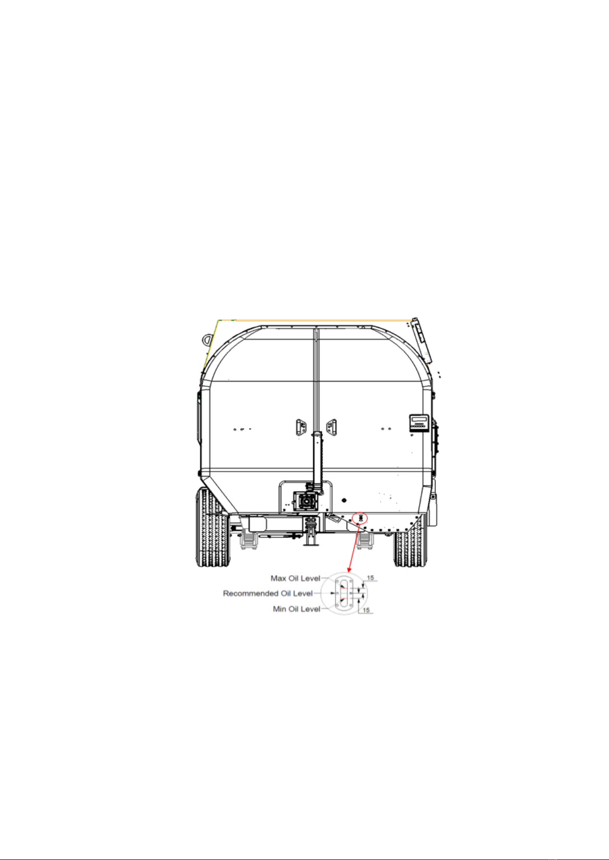
The oil reservoir (or sump) is located on the left side of the drive system. Each day, check the
level of the oil reservoir. Before checking the oil level, ensure that the machine is sitting level
(both front to rear and left to right). An oil-level viewing window has been fitted to the front panel
of the drive system and can be viewed when the front left hand cover is opened. The
recommended oil level should be midway along this window. This represents 28 litres of oil in
the sump. The minimum level is -15 mm from the centre and the maximum level is +15 mm from
the centre.
If the oil level is low, top it up with chain-bar oil (the properties of which allow it cling to the
chains longer). Use Total/Finol Chainac MP if available or a suitable equivalent (volumetric mass
of 879 kg/m3 @ 15°C and viscosity rating of 150mm2/s @ 40°C). Do not use grease on the chains,
as it is unsuitable for the application and will not allow for the lubrication of the vital internal
parts of the chain.
1.5 Chain tensioning
With use, the drive chains will extend slightly over time. To compensate for this, all KEENAN
MechFiber machines are fitted with a tensioner mechanism on the slack side of the chain. The
primary and secondary chain tensioners comprise of a pivoting tension arm connected to a
tension spring and adjusted via a threaded bolt passing through a shoulder plate. The rotor chain
tensioner comprises of a pivoting tension arm connected to a compression spring and adjusted
via a second pivoting arm with locating bolt holes. The auger chain tensioner comprises of a
pivoting tension arm connected to a compression spring via a pull rod and adjusted via a
Figure 3: Oil level

KEENAN MechFiber400+ Operator’s Manual Rev H02 Feb 20238
threaded spring seat on the end of this rod. In order to prevent the chain jumping and premature
wear the chain must be held at the correct preload tension at all times and should be checked
weekly.
1. Setting tension on the primary chain
This preload tension can be set by adjusting the vertical threaded bolt in the centre of the drive
system (adjuster “A” in Figure 1 and Figure 4). The correct tension will be applied to the chain
when the tension spring is extended to 220 mm between mounting centres. Once set, retighten
all locking nuts. It is recommended to check the tension weekly in the first few weeks of
operation as the chain, sprockets and tensioner “beds in” and may need to be adjusted.
Figure 4: Primary chain tensioner spring setting
2. Setting tension on the secondary chain
The preload tension on this chain can be set by adjusting the horizontal threaded bolt situated
behind the secondary idler shaft driven sprocket (adjuster “B” in Figure 1 and Figure 5). As above
the correct tension will be applied to the chain when the tension spring is extended to 235 mm
between mounting centres. Once set, retighten all locking nuts.
Figure 5: Secondary chain tensioner spring setting

KEENAN MechFiber400+ Operator’s Manual Rev H02 Feb 20239
3. Setting tension on the auger chain
The preload tension on this chain can be set by adjusting the horizontal threaded spring seat
situated to the front of the drive system (adjuster “C” in Figure 1 and Figure 6). The correct
tension will be applied to the chain when the spring is compressed to 180 mm. Once set,
retighten the locking nut against the seat.
Figure 6: Auger chain tensioner spring setting
4. Setting tension on the rotor chain
The preload tension on this chain can be set using the adjuster pivot arm mechanism on the left
side of the machine directly below the auger shaft (adjuster “D” in Figure 1 and Figure 7). To
access this mechanism, open the left cover. Open the nut from the M16 fixing bolt and using a
spring clamp or a lever bar compress the spring and remove the bolt. Using the same method as
before now compress the spring to approx. 255 mm. Ensuring that the spring is seated correctly,
replace the M16 bolt and nut in the appropriate position and tighten.
Figure 7: Rotor chain tensioner spring setting

KEENAN MechFiber400+ Operator’s Manual Rev H02 Feb 202310
It is recommended to check the tension weekly in the first few weeks of operation, as the
chain, sprockets and tensioner “beds in” and may need to be adjusted
1.6 Greasing
The KEENAN MechFiber400+ is fitted with a central greasing manifold as standard, located at
the left side of the front cover. It allows greasing of all the inaccessible grease points of the drive
system of the machine from that on location. The manifold groups pivot points 20, 24, 25, 26,
27, 28, 29, 30, 31, 32, 33 and 34 together, large bearing points 3, 4, 5, 6, 7 and 9 together,
medium bearings grease points 1 and 2 together and small bearing points 11 and 12 together.
An instruction decal is fitted above the central greasing manifold on the front cover detailing the
greasing interval (40 hours) and the amount of grease to be applied to each point (see Figure 9).
All other bearings and pivot points not serviced by this manifold should receive 3cc (5g/0.175oz)
of grease at the same 40-hour intervals.
1. Bearings - Each week (every 40 hours) apply grease to the 12 main bearings. These are
as follows:
Grease point 1 Input shaft bearing (front) (see Figure 10)
Grease point 2 Input shaft bearing (rear) (see Figure 10)
Grease point 3 Primary idler shaft bearing (front) (see Figure 10)
Grease point 4 Primary idler shaft bearing (rear) (see Figure 10)
Grease point 5 Secondary idler shaft bearing (front) (see Figure 10)
Grease point 6 Secondary idler shaft bearing (rear) (see Figure 10)
Grease point 7 Rotor bearing (front) (see Figure 10)
Grease point 8 Rotor bearing (rear) (see Figure 11)
Grease point 9 Auger bearing (front) (see Figure 10)
Grease point 10 Auger bearing (rear) (see Figure 11)
Grease point 11 Primary drive chain tensioner sprocket bearing (see Figure 10)
Grease point 12 Secondary drive chain tensioner sprocket bearing (see Figure
10)
WARNING:
Larger drive chains exceed manual handling limits. If removing or refitting
always use suitable lifting equipment.
Primary drive chain (540 RPM input) 15 kg
Primary drive chain (1000 RPM input) 23 kg
Secondary drive chain 42 kg
Rotor drive chain 141 kg
Auger drive chain 15 kg

KEENAN MechFiber400+ Operator’s Manual Rev H02 Feb 202311
1. Pivot pins - Each week (or every 40 hours) apply grease to the following pivot points
also:
Grease point 13 Drawbar centre pivot pin (see Figure 12)
Grease point 14 Drawbar spring to hanger pivot pin (see Figure 12)
Grease point 15 Drawbar spring hanger top pivot pin (see Figure 12)
Grease point 16 2 on each brake rod (8 in total) (see Figure 12)
Grease point 17 1 on each brake arm (4 in total) (see Figure 12)
Grease point 18 1 on each spring front pin (4 in total) (see Figure 12)
Grease point 19 1 on each spring centre pivot assembly (2 in total) (see Figure 12)
Grease point 20 VFC-door front ram pin (top) (see Figure 10)
Grease point 21 VFC-door front ram pin (lower) (see Figure 13)
Grease point 22 VFC-door rear ram pin (top) (see Figure 13)
Grease point 23 VFC-door rear ram pin (lower) (see Figure 13)
Grease point 24 Primary drive chain tensioner arm pivot pin (see Figure 10)
Grease point 25 Secondary drive chain tensioner arm pivot pin (see Figure 10)
Grease point 26 Rotor drive chain tensioner arm pivot pin (see Figure 10)
Grease point 27 Auger drive chain tensioner arm pivot pin (see Figure 10)
Grease point 28 Rotor drive chain adjuster arm pivot pin (see Figure 10)
Grease point 29 Rotor drive tensioner spring inner seat bush (see Figure 10)
Grease point 30 Rotor drive tensioner spring outer seat bush (see Figure 10)
Grease point 31 Rotor drive chain tensioner spring seat shaft (see Figure 10)
Grease point 32 Auger drive chain tensioner adjuster pivot bush (see Figure 10)
Grease point 33 Auger chain tensioner compression spring seat pivot bush (see
Figure 10)
Grease point 34 Auger chain tensioner compression spring inner seat (see Figure
10)
2. VFC-door - Check the VFC-door is able to move freely each day and grease external slides
as appropriate.
3. PTO drive shaft - Refer to PTO operators manual for greasing instructions and
recommendations
Figure 8: Drive system central greasing manifold
Grease manifold
location

KEENAN MechFiber400+ Operator’s Manual Rev H02 Feb 202312
Apply grease at 40-hour intervals
Pivot points
Large bearings
Medium bearings
Small bearings
3 pumps/3 cc
4 pumps/4 cc
3 pumps/3 cc
1 pump/1 cc
5 grams/0.175 oz
7.2 grams/0.26 oz
5 grams/0.175 oz
2 grams/0.035 oz
Note: 1 pump/stroke of manual grease gun typically produces 1 cc of grease
Figure 9: Central greasing application detail
Figure 10: Central greasing manifold ports
Figure 11: Rear greasing point
Grease point 10
Grease point 8
Grease point 8

KEENAN MechFiber400+ Operator’s Manual Rev H02 Feb 202313
Figure 12: Chassis greasing points
Figure 13: VFC-door greasing points
Grease point 22
Grease point 23
Grease point 21
Grease point 16
Grease point 13
Grease point 14
Grease point 19
Grease point 18
Grease point 17
Grease point 15
Grease point 22
Grease point 23
Grease point 21
Grease point 16
Grease point 14
Grease point 13
Grease point 19
Grease point 18
Grease point 15
Grease point 17

KEENAN MechFiber400+ Operator’s Manual Rev H02 Feb 202314
1.7 Blade maintenance
Blade sharpening and/or replacement:It is recommended that only KEENAN-trained and/or
qualified maintenance personnel should perform this task.
Blades need to be kept sharp. Blunt blades will increase power requirements. Sharpening
must be done without taking the temper from the blades (i.e., without overheating). Blades can
be sharpened many times, but when they reach the point where this is no longer practical, they
must be replaced.
1.8 Shear bolts
The following are the recommended shear bolts to be used with the KEENAN MechFiber400+.
Table 3: Shear bolt size and grade
1.9 Nuts and bolts
1. After the first day, and regularly thereafter, inspect wheel nuts and tandem-axle U-bolts
(where fitted).
2. After the first week, and each week thereafter, check all nuts and bolts, including bearing
nuts, for tightness.
General torque
Table 4: General torque for wheel studs
Table 5: Recommended torque for U-bolts for tandem axles (where fitted)
Machine type
PTO shaft
Shear bolt
Colour code
540 RPM input
T80 and V80
M12 x 70 x 5.6
Blue
1000 RPM input
T60 and V60
M10 x 60 x 4.6
Green
CAUTION:
Failure to use the correct grade of shear bolt can result in overload failure of the
machine and will invalidate your warranty.
Stud/bolt type
FT/LB
N.M
M22
335
450
M20
260
350
M18
200
270
U-bolt diameter (mm)
Tightening torque (Nm)
18
230
22
450
24
500
27
600

KEENAN MechFiber400+ Operator’s Manual Rev H02 Feb 202315
Figure 14: U-bolt position on bogie axle
1.10 Tyres
1. Each week, check the tyres for wear and damage.
2. Each week, check the tyre pressure. Optimal tyre pressures are shown in Table 6.
This information is given as guidance. If in doubt, please contact your KEENAN service partner.
WARNING:
When refitting and re-inflating tyre/wheel assemblies, a safety cage should be used
to prevent possible injury. Incorrectly fitted tyres are dangerous. Please make sure
tyre repairs are carried out by experienced tyre fitters.
Type
Bar
PSI
385/65 R 22.5
9.0
132
385/55 R 22.5
9.0
132
445/45 R 19.5
9.0
132
Table 6: Tyre pressure
1.11 Hitch height adjustment
The hitches of the KEENAN MechFiber400+have been designed to allow for a number of various
hitch height options with the same components used. The hitch height is normally selected for
the application and set at the factory per the options below.
The main standard hitch assembly is a bolt-on assembly, and once the main setting is completed
at the factory, it may also be adjusted on-farm if necessary.
Note:
1: Care must be taken when adjusting the hitch height so that there is adequate PTO clearance and that
there is enough ground clearance below the stand.

KEENAN MechFiber400+ Operator’s Manual Rev H02 Feb 202316
Figure 15a: Hitch height settings on 385/65R 22.5 wheels/tyres

KEENAN MechFiber400+ Operator’s Manual Rev H02 Feb 202317
Figure 15b: Hitch height settings on 385/55R 22.5 wheels/tyres

KEENAN MechFiber400+ Operator’s Manual Rev H02 Feb 202318
Figure 15c: Hitch height settings on 445/45R 19.5 wheels/tyres

KEENAN MechFiber400+ Operator’s Manual Rev H02 Feb 202319
1.12 Specifications
Table 7: Machine weights
1. Weights may vary depending on the exact specifications.
1.13 Soda grain
Additional safety instructions and warnings are available and covered in the soda grain leaflet,
which should be read carefully before soda-treating grain. When you are finished treating the
grain, clean out any remaining material in the mixing and/or auger chamber by loading in 200–
300 kg of silage or 50 kg of straw, and allow the machine to mix before unloading in the normal
manner.
*Note that when mixing soda grain, the maximum gross load that can be mixed in the KEENAN
MechFiber400+ is 8,000 kg/17,600 lbs.
The soda-grain process can be completed using a KEENAN mixer, but before completing
treatment on your farm, make sure you are adhering to the local animal feed legislation and
health and safety guidelines involving the treatment of grain.
Model
MechFiber400+
Non-Bale Handler
Bale handler
Unladen
kgs
13,750
14,750
lbs.
30,313
32,518
Payload
kgs
10,000*
lbs.
20,046*
Gross
kgs
23,750
24,750
lbs.
52,359
54,564
Table of contents