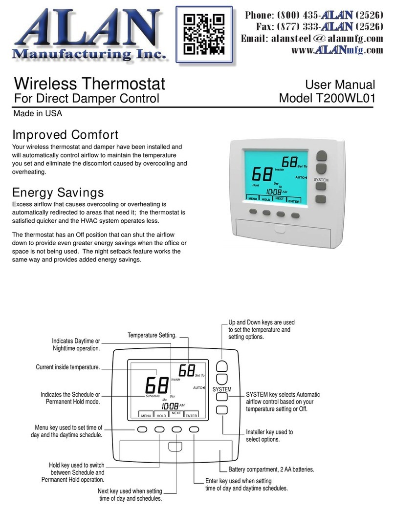
Alan T200WLZ1 Assembly instructions

SYSTEM
FAN
Temperature Control
System Operation
Fan Control
Programs
Compatible Systems
LCD Display
Communication
Range
Compatible Panels
Housing
T200WLZ1 Power
T200WLZ2 Power
Dimensions
Scheduled operation, Temporary Hold
or Permanent Hold.
Off, Heating, Cooling, Auto
Heating/Cooling and Emergency Heat
for heat pumps.
Automatic or Continuous operation.
Four per day, 7-day programmable.
Gas/electric, heat pumps, single or
multi-stage depending on HVAC
module used.
Large LCD display, blue backlighting.
Wireless, 915MHz, proprietary protocol.
More than 100 feet in a structure.
eWL4 wireless zoning panel.
Molded plastic case.
Battery powered, two AA batteries.
Batteries install from front of thermostat.
Powered from the eWU4 panel with two
AA batteries used for backup.
4.95 x 4.40 x 1.05 inches (WHD)
Installer Guide T200WLZ1 and T200WLZ2
Wireless Zoning Thermostat
Rev 9/20/12
Hold the sub-base with one hand, press the case as shown
below and pull the bottom of the thermostat from the sub-base.
Press here to release
case from sub-base.
Before Installation
Remove the Sub-base
1
The thermostat can be installed on any interior wall
approximately 5 feet above the floor. To insure accurate
reading of the space temperature, the thermostat should not be
in direct sunlight.
Install the sub-base using two #8 or #6 sheet metal screws
with wall anchors where required. Level the thermostat for
appearance.
Installing the Sub-Base
2
Slide the battery cover off and install two AA lithium or alkaline
batteries. Install the batteries with the positive terminals to the
right as shown. Replace the battery cover.
The LCD will display the time of day, the setpoint temperature
and the room temperature.
Installing the Batteries
3
Manufacturing Inc.
Phone: (800) 435-
ALAN
(2526)
Fax: (877) 333-
ALAN
(2526)
www.
ALAN
mfg.com

2
Option Description
Zone number
Range
Range
Range
Range
Range
Range
Range
Range
Range
Range
Range
Range
1 to 4
1 to 7
00- G/E 01- Heat Pump
1 to 9 minutes
60 to 85F
1 to 4F
2 to 6F
1 to 10F
1 to 12F
1 to 12F
55 to 80F
1 to 9 minutes
Default
Default
Default
Default
Default
Default
Default
Default
Default
Default
Default
Default
1
1
00- G/E
0 minutes
85F
1F
2F
3F
5F
5F
65F
0 minutes
Address number
Equipment type
Minimum Off Time
Minimum Run Time
Maximum allowable heating setpoint
Minimum allowable cooling setpoint
Stage1 Temperature Differential
Heat/Cool Setpoint Differential
Stage 2 Temperature Differential
Stage 3 Temperature Differential
Stage 4 Temperature Differential
01
02
03
11
12
09
10
04
05
06
07
08
Accessing the
Installation Options
4
The installer options can be accessed by pressing and holding
the Enter key for seven seconds. The LCD will display Option
01 for setting the Zone number.
Press and release the Next key to advance to the next option.
The LCD will advance to Option 12 and return to Option 01.
Press the Cancel key to exit the option selections. Press the
Enter key to save all options in non-volatile flash ram.
Press ENTER for 7 seconds.
Press Up or Down key to
change zone number.
Press Up or Down key to
change home number.
Press Up or Down key to
toggle between 00 for GE or
01 for HP operation.
Press NEXT key to continue.
Press CANCEL key to return to
normal thermostat operation
without saving the changes.
Press CANCEL key to return to
normal thermostat operation
without saving the changes.
Press CANCEL key to return to
normal thermostat operation
without saving the changes.
Press ENTER key to save the
changes to flash memory and
return to normal thermostat
operation.
Press ENTER key to save the
changes to flash memory and
return to normal thermostat
operation.
Press ENTER key to save the
changes to flash memory and
return to normal thermostat
operation.
Press NEXT key to continue.
Use the Up and Down keys to set the Zone number for the
thermostat. The Zone number can be set from 1 to 4.
Option
Zone
CANCEL NEXT ENTER
Option 01 Setting the Zone Number
Default= 01
501
The Home address is used to distinguish between installations
that are less than 500 feet away. This allows neighbors,
different departments or floors to use the wireless thermostats
and not interfere with each other. Skip to Setting Option 03 if
no other users are nearby.
Option
Home
CANCEL NEXT ENTER
Option 02 Setting the Home Number
Default= 01
5
02
Option 03 Selecting equipment Type
Default= Gas/Electric
503
HVAC Control Module with the appropriate output terminals
can be set for either gas/electric or heat pump operation.
Press the Up or Down key to select 00- Gas/Electric or 01-
Heat Pump operation.
Option
CANCEL NEXT ENTER
Inside
Option
Mo
Schedule Day
AM
Heat
AUTO
HEAT
Set To
MENU HOLD NEXT ENTER
ENTER
NEXT
CANCEL
CANCEL
CANCEL
ENTER
ENTER
ENTER
NEXT
NEXT

3
Option 04 Setting Heat/Cool Setpoint
Temp Differential. Default=2F
504
The Heat/Cool temperature differential prevents the heating
setpoint from being set above or too close to the cooling
setpoint, resulting in inadvertent cycling between heating and
cooling.
Option
CANCEL NEXT ENTER
Option 05 Setting Stage1 Differential
Default= 1F
505
Stage1 temperature differential determines the sensitivity of
the thermostat. A lower differential will cause the thermostat to
cycle more often with smaller temperature swings. If the
temperature differential between indoor temperature and
setpoint temperature is greater than the Stage1 Temperature
Differential, first stage heating or cooling will be activated.
Option
CANCEL NEXT ENTER
Option 06 Setting Stage2 Differential.
Default= 3F
506
The Stage2 Temperature Differential determines when the
equipment advances from first to second stage. If the
temperature differential between indoor temperature and
setpoint exceeds the Stage2 Temperature Differential, the
equipment activates second stage heating or cooling.
Option
CANCEL NEXT ENTER
Option 07 Setting Stage3 Differential
Option 08 Setting Stage4 Differential
Default= 5F
Default= 5F
5
5
07
08
The Stage3 Temperature Differential determines when the
equipment advances from second to third stage. Setting the
differential temperatures the same for Stage2 and Stage3
different turns second and third stage on at the same indoor
temperature. The Stage3 Temperature Differential cannot be
set below the Stage2 differential.
The Stage4 Temperature Differential determines when the
equipment advances from third to fourth stage. Setting the
differential temperatures the same for Stage3 and Stage4
turns third and fourth stage on at the same indoor
temperature. The Stage4 Temperature Differential cannot be
set below the Stage3 differential.
Option
Option
CANCEL
CANCEL
NEXT
NEXT
ENTER
ENTER
Option 09 Setting Maximum Heating
Setpoint. Default=85F
509
The maximum heating setpoint the user can set is 60 to 85F.
Option
CANCEL NEXT ENTER
Press Up or Down key to
change heating/cooling
setpoint differential.
Press Up or Down key to
change stage1 call temperature
differential.
Press Up or Down key to
change stage3 call temperature
differential.
Press Up or Down key to
change stage4 call temperature
differential.
Press Up or Down key to
change maximum allowable
heating setpoint temperature.
Press Up or Down key to
change stage2 call temperature
differential.
Press NEXT key to continue.
NEXT
NEXT
NEXT
NEXT
NEXT
NEXT
Press CANCEL key to return to
normal thermostat operation
without saving the changes.
Press CANCEL key to return to
normal thermostat operation
without saving the changes.
Press CANCEL key to return to
normal thermostat operation
without saving the changes.
Press CANCEL key to return to
normal thermostat operation
without saving the changes.
Press CANCEL key to return to
normal thermostat operation
without saving the changes.
Press CANCEL key to return to
normal thermostat operation
without saving the changes.
Press ENTER key to save the
changes to flash memory and
return to normal thermostat
operation. Press ENTER key to save the
changes to flash memory and
return to normal thermostat
operation.
Press ENTER key to save the
changes to flash memory and
return to normal thermostat
operation.
Press ENTER key to save the
changes to flash memory and
return to normal thermostat
operation.
Press ENTER key to save the
changes to flash memory and
return to normal thermostat
operation.
Press ENTER key to save the
changes to flash memory and
return to normal thermostat
operation.
CANCEL
CANCEL
CANCEL
CANCEL
CANCEL CANCEL
ENTER
ENTER
ENTER
ENTER
ENTER ENTER

Option 10 Setting Minimum Cooling
T200WLZ2 Power Wiring
T200WLZ2 Thermostat
setpoint. Default=65F
5 610 01
The minimum cooling setpoint the user can set is 55 to 80F. The T200WLZ2 can be used in Zone1 and powered from the
panel using two of the existing thermostat wires. This insures
reliable control of the system should the user fail to change the
thermostat batteries.
Option
CANCEL NEXT ENTER
Option 12 Setting Minimum Run Time
Default =0 minutes
512
The Minimum Run Time influences the cycling rate and helps
to evaporate condensation in heat ex-changers.
Option
CANCEL NEXT ENTER
Option 11 Setting Minimum Off Time
Default= 0 minutes
511
The minimum Off time prevents the compressor from restarting
too quickly. Large HVAC systems should use a longer Off
time. The minimum Off time and the minimum Run time also
influence the cycling rate.
Option
CANCEL NEXT ENTER
Rev 6/10/11
Press Up or Down key to
change lowest allowable
cooling setpoint temperature.
Press Up or Down key to
change the minimum system
off time in minutes.
Press Up or Down key to
change the minimum system
run time in minutes.
Press NEXT key to continue.
Press NEXT key to return to
Option 01.
Or press ENTER key to save
your selections.
NEXT
NEXT
NEXT
ENTER
Press CANCEL key to return to
normal thermostat operation
without saving the changes.
Press CANCEL key to return to
normal thermostat operation
without saving the changes.
Press ENTER key to save the
changes to flash memory and
return to normal thermostat
operation.
Press ENTER key to save the
changes to flash memory and
return to normal thermostat
operation.
CANCEL
CANCEL
ENTER
ENTER
Inside
Mo
Schedule Day
AM
Heat
AUTO
HEAT
Set To
MENU HOLD NEXT ENTER
SYSTEM
FAN
+8V
GND
+8V
GND
WLPWR
GND
ALAN Manufacturing. 3927 E. Lincoln Way, Wooster, OH 44691
800-435-2526 Fax 877-333-2526 www.alanmfg.com
Manufacturing Inc.
This manual suits for next models
1
Other Alan Thermostat manuals