Kanmor 540e User manual

Information
Brochure
Choose controls
to match
application
1Application
Brochure
Design your
mechanical
applications
2Rough In
Wiring
Rough-in
wiring
instructions
3Wiring
Brochure
Wiring and
installation of
specific control
4Data
Brochure
Control settings
and sequence of
operation
5Job
Record
Record settings &
wiring details for
future reference
6
D540e
02/08
tekmarNet®4 Thermostat 540e
- Data Brochure
1 of 12 © 2008 D540e - 02/08
•
• tN4 Communication Compatible
•
• Requires 6 Wires (tN4, C, R, W, G, Y)
•
• One Stage Heat
•
• One Stage Cool
•
• One Fan
•
• Pulse Width Modulation
•
•
CE Approved
•
• Schedule Member (Follows Schedule Master)
•
• Optimum Start
•
• Scenes
•
• Outdoor Temperature Display
•
• Backlight
•
• Exercising
•
• Freeze Protection
The tekmarNet®4 Thermostat 540e operates a single stage of heating, single stage cooling, and a single fan.
Introduction
Features

© 2008 D540e - 02/08 2 of 12
Table of Contents
Table of Contents........................................................2
Display and Switch Settings .......................................2
Switch Settings ...................................................2
Display and Symbols Description........................3
Button Operation.................................................4
Setting the Temperature......................................4
Display Settings..........................................................5
User Settings .....................................................5
Adjust Menu For installer use only......................6
Sequence of Operation ..............................................7
Heating Operation ..............................................7
Cooling Operation ..............................................7
Fan Operation ....................................................7
Outdoor Temperature Display.............................8
Schedules ..........................................................8
Optimum Start ....................................................8
Scenes ...............................................................8
Cool Group Master..............................................9
Backlight .............................................................9
Warm Weather Shutdown ..................................9
Freeze Protection ...............................................9
Cycles Per Hour .................................................9
Synchronization .................................................9
Indoor Temperature Feedback ......................... 10
System Pump ...................................................10
Exercising .........................................................10
Zone Test ......................................................... 10
Max Heat .......................................................... 10
Flushing ...........................................................10
tN4 Address ..................................................... 10
Error Messages ........................................................ 11
Cleaning the Thermostat ......................................... 12
Warranty ................................................................... 12
Display and Switch Settings
Switch Settings
12 34
tNt 540e
540e
1001-07
12 34
Switch Position Action
1
ON
Setback
The thermostat follows a
programmable setback
schedule as a schedule
member if available.
OFF
OFF
The thermostat does not follow
a programmable setback
schedule.
2
ON
Scene
The thermostat responds to
changes in the scene (system
wide manual overrides).
OFF OFF
The thermostat does not
respond to scenes.
3
ON None
The thermostat is not part of a
cooling group.
OFF Cool Master 1
The thermostat is a master of
cooling group number 1.
4
ON Hydronic
Hydronic heat source.
OFF Other
Other heat source (Furnace,
Electric).
*Read the Sequence of Operation for detailed information on
each of the switch setting features.

3 of 12 © 2008 D540e - 02/08
Display
Symbols Description
HEAT
Heat is turned on.
COOL
Cooling is turned on.
FAN
Fan is turned on.
SUN
Operating at the occupied (day)
temperature.
MOON
Operating at the unoccupied (night)
temperature.
CLOCK
Operating on a programmable
schedule.
AWAY
Operating at the Away scene
temperature.
WARM WEATHER SHUT DOWN
The heating system has been shut off
for the summer.
COOL GROUP MASTER
Thermostat operates the cooling for a
group of thermostats.
tN4 COMMUNICATION
Communication is present.
WARNING SYMBOL
Indicates an error is present.
SECONDARY
DISPLAY
MAIN
DISPLAY

© 2008 D540e - 02/08 4 of 12
Vent Mode: Only the fan operates to circulate air. The
heating and cooling are not operated.
Off Mode: The heating, cooling, and fan are shut off
except heating for freeze protection.
Button
Button Operation
Mode Button
Cool Mode: The cooling system operates to maintain
the Set Room temperature. The fan operates whenever
the cooling is on.
Auto Mode: The heating system operates to maintain the
Set Room Heat temperature. Likewise the cooling system
operates to maintain the Set Room Cool temperature.
The Set Room Heat and the Set Room Cool settings
must always be at least 3°F (1.5°C) apart. Should the
Heat setpoint be raised within 3°F (1.5°C) of the Cool
setpoint, the Cool setpoint is automatically adjusted
higher. Likewise, if the Cool setpoint is lowered within
3°F (1.5°C) of the Heat setpoint, the Heat setpoint is
automatically adjusted lower.
To switch from heating to cooling, the heat must be off
for at least a 30 minute interlock period and the Room
temperature must exceed 3°F (1.5°C) above the Set
Room Heat temperature.
To switch from cooling to heating, the cooling must be off
for at least a 30 minute interlock period and the Room
temperature must exceed 3°F (1.5°C) below the Set Room
Cool temperature. Cooling has priority over heating.
The fan operates whenever the cooling is on. The fan will
turn on with the heating if fan mode 2 is selected.
The Mode button selects between Auto,
Cool, Heat, Vent and Off.
Heat Mode: The heating system operates
to maintain the Set Room temperature.
The fan may turn on with the heating
if the setting is selected.
Room Temperature
Press the or the button to select the room temperature.
The display indicates whether the “HEAT” or the “COOL”
temperature is being changed.
If in Auto mode, press the Mode button to toggle between
Heat or Cool temperature adjustment.
Programmable Schedule
When operating on a programmable schedule, a symbol
is shown, as well as a or a . The or indicates
the current operating temperature.
Press the Local Override ( ) button to select the
to operate on a programmable schedule.
If a symbol does not appear, there is no schedule
available.
Display Action
Manual override at occupied temperature.
Manual override at unoccupied temperature.
Programmable schedule at
occupied
temperature.
Programmable schedule at
unoccupied
temperature.
FUse the or
button to adjust
temperature.
Setting the Temperature
The button raises the Set Room
temperature. When in Ventilation mode,
the button increases the Set Fan
percentage.
Button
The button lowers the Set Room
temperature. When in Ventilation mode,
the button decreases the Set Fan
percentage.
Local Override Button
The Local Override ( ) button
changes between the local override
temperatures.
The option is permanent , permanent ,
or follow the programmable schedule .

5 of 12 © 2008 D540e - 02/08
Local Override
The Local Override ( ) button can be used to override
any schedule. Press and release the button to toggle
between , , and (if available).
The thermostat remains at the selected or override
temperature until manually changed back to the
schedule.
Scene Display
1or or
2Away
3
Occupied Unoccupied Schedule
Scenes (System Override)
When using scenes, there are three temperature settings:
, , Away. The scene takes precedence over any local
overrides or any programmable schedules.
While in the Away scene, the room temperature cannot be
changed using the or buttons. Change the scene
from Away to or to change the temperature.
While in the or Away scene and the button is
pressed, the or Away icon will flash. Scene 1 ( or
or ) must be activated before the thermostat
responds to the button.
Display Description
STEP 1
°F or °C Press the or the button to change from °F to °C and vice
versa.
STEP 2
View Type and Software
Version
The large number shows the type number as 540.
The software version is shown in the upper right hand corner.
STEP 3
View tN4 Address
The thermostat’s tN4 address is shown.
The address toggles between a number and “Au” when using
automatic addressing.
STEP 4
Manually Change tN4
Address
Press the or the button to manually select an address.
The address can be returned to automatic “Au” between addresses
24 and 1.
Ensure to document the address number when manually addressing
thermostats.
User Settings (1 of 1)
•
• Press and hold down both the and buttons to change from one step to the next. While
holding both buttons down, a new setting will display every 5 seconds.
•
• Release both buttons once the step has been reached.
•
• Press the or the button to change the setting, if available.
•
• Press and hold down both the and buttons for 5 seconds to go to the next step, OR
•
• After 10 seconds of no button activity, the display goes back to normal operation.
Press
+
Together
ButtonPress the
Display Settings

© 2008 D540e - 02/08 6 of 12
Display Range Description
40 to 85°F
(4.5 to 29.5°C)
Default = 70°F
(21.0°C)
SET ROOM HEAT
Set the room heating temperature while in the event.
40 to 85°F
(4.5 to 29.5°C)
Default = 65°F
(18.5°C)
SET ROOM HEAT
Set the room heating temperature while in the event.
40 to 85°F
(4.5 to 29.5°C)
Default = 62°F
(16.5°C)
SET ROOM HEAT AWAY
Set the room heating temperature while in the Away scene.
40 to 85°F
(4.5 to 29.5°C)
Default = 78°F
(25.5°C)
SET ROOM COOL
Set the room cooling temperature while in the event.
40 to 85°F
(4.5 to 29.5°C)
Default = 85°F
(29.5°C)
SET ROOM COOL
Set the room cooling temperature while in the event.
40 to 85°F
(4.5 to 29.5°C)
Default = 85°F
(29.5°C)
SET ROOM COOL AWAY
Set the room cooling temperature while in the Away scene.
1 or 2
Default = 1
FAN MODE
Select if the fan should operate with cooling (Fan Mode 1), or
with the heating and cooling (Fan Mode 2).
OFF, On
Default = OFF VENTILATION
Select whether or not ventilation is required.
Auto, 10 to 90%,
On
Default = Auto
FAN
Set the minimum percentage the fan should operate while in
the event. This provides ventilation for the building.
Available when:
•
• Ventilation is set to On.
Adjust Menu (1 of 2) *for installer use only
These settings are intended for use by the installer only and are
not required for use by average users of the thermostat.
•
• Press and release the Mode, , and buttons together.
•
• Press and release the Mode button to go to the next
setting.
•
• Once all settings are complete, wait 20 seconds for the
thermostat to return to normal operation.
ADJUST MENU
Continued on next page.
Press
+ +
Together

7 of 12 © 2008 D540e - 02/08
Display Range Description
Auto, 10 to 90%,
On
Default = Auto
FAN
Set the minimum percentage the fan should operate while in
the event. This provides ventilation for the building.
Available when:
•
• Ventilation is set to On.
Auto, SYn
Default = Auto
HEAT CYCLES PER HOUR
Select either Auto cycle or Synchronize with other thermostats
on the tN4 system.
Available when:
•
• There is no reset module on the tN4 bus.
1 or 2
Default = 1
SCHEDULE
Thermostat can follow schedule 1 or 2.
Available when:
•
• Switch setting 1 is set to Setback (On Position).
Heating Operation
Sequence of Operation
The thermostat operates the heating system to maintain
the Set Room Heat temperature. The heat source can
be either hydronic or other. This is selected by switch
setting 3.
When switch setting 3 is set to hydronic (On position), the
thermostat uses indoor temperature feedback and also
synchronizes the starting of a heating cycle.
When switch setting 3 is set to other (Off position), the
thermostat does not use indoor temperature feedback.
This allows the thermostat to operate non-hydronic
heating systems (i.e. furnace, electric baseboard, or
electric fan coil), while remaining connected to the tN4
communication system.
Cooling Operation
The thermostat operates the cooling system to maintain the
Set Room Cool temperature. The fan turns on whenever
the cooling system is on.
The cooling system has a fixed minimum on time of 2
minutes and a minimum off time of 5 minutes in order to
prevent cooling equipment short cycling.
Adjust Menu (2 of 2) *for installer use only
ADJUST MENU
After the last item, the control returns to the first item in the Adjust menu.
Fan Mode The fan operates with...
1 Cooling Only
2 Heating and Cooling
Fan Operation
The Fan Mode setting determines how the fan operates
with the heating and cooling systems.
Locate the Fan Mode setting in the Adjust menu.
The fan relay includes a post purge feature. After the
heating is shut off, the fan continues to operate for 30
seconds. After the cooling is shut off, the fan continues
to operate for 10 seconds.
The fan can also operate for additional time beyond what
is required for the heating and cooling systems in order to
provide ventilation to the building. Ventilation is provided
when Mode is set to Heat, Cool, Auto, or Vent. There is
no ventilation when Mode is set to OFF.
Locate the Ventilation setting in the Adjust menu and
set to On.
Once this is done, two additional settings are available
for the Fan minimum run time percentage during the
and events.
Locate the Fan and Fan settings in the Adjust menu
and set the desired percent run time per hour using the
or button.

© 2008 D540e - 02/08 8 of 12
Outdoor Temperature Display
When the thermostat is connected to a tN4 system that
includes an outdoor sensor, the outdoor temperature is
displayed in the upper right hand corner of the display.
Schedules
This thermostat, when connected to a tN4 communication
bus, can follow a programmable schedule in order to
automatically lower the room temperature setting.
Lowering the room temperature setting reduces the
amount of fuel required to heat the building resulting in
energy savings.
For this thermostat to follow a schedule, a device called
a schedule master is required. A schedule master can
be a programmable tN4 Thermostat 546e or 542e, a
programmable tN4 Timer 033e, or other tN4 devices that
indicate they are a tN4 schedule master.
The schedule master may support multiple system
schedules. This thermostat can follow either system
schedule 1 or 2.
To follow a schedule:
•
• Select switch setting 1 to Setback (On position).
•
• Locate the schedule item in the Adjust menu. Select
either system schedule 1 or 2.
540e
tN4 Communication
Programmable
Schedule
Device
Schedule Master
Optimum Start
When a programmable schedule is selected, there is
a time delay for the temperature to change from the
temperature to the temperature.
The thermostat uses an Optimum Start feature to predict
the heat up rate of the room. The optimum start feature
allows the room to reach the set room temperature by
the time set in the programmable schedule.
During the time period, the user may notice the heat
being on even though the room temperature is above
the set room temperature. This is due to the Optimum
Start feature heating the room in order to reach the
temperature on time.
The Optimum Start applies for both the heating and the
cooling systems. When the mode is set to Auto, Optimum
Start prioritizes for the heating system.
Optimum Start
10P.M. 5A.M. 8A.M.
Occ
70°F (21°C)
UnOcc
65°F (18°C)
Room
Temp.
Recovery Period
Optimum
Start
Setback
Period
Scene Room Temperature Setting
1Follows programmable schedule if available.
If there is no schedule, operates at the
occupied temperature.
2 Away temperature.
3Unoccupied temperature.
Scenes
Scenes are system wide manual overrides. By changing
the scene number, all scene participating thermostats
change their operating temperature at the same time.
The scene overrides any time-scheduled changes in
temperature.
The purpose of scenes is to provide a quick and convenient
method to lower the heating temperature (raises the
cooling temperature) on multiple thermostats throughout
a building. This reduces the amount of fuel required to
heat the building resulting in energy savings.
Scenes are often used when leaving on vacation, holidays,
or special events.
In order to use the scene feature, a device called a User
Switch (sold separately) can be used to change the
scene number.
This thermostat supports scenes 1, 2, and 3. Scenes 4
through 8 are not supported. Should a permanent scene
4 or 5 be activated, the thermostat operates in scene 1.
Should a temporary scene 6, 7, or 8 be activated, the
thermostat does not change and remains in the last
supported scene.
This thermostat can participate with scenes when switch
setting 2 is set to scene (On position).
User Switch

9 of 12 © 2008 D540e - 02/08
Cool Group Master
Cool Group 1
Master MemberMember
tN4 Communication
In order to prevent heating and cooling at the same time,
this thermostat can operate together with other thermostats
on a tN4 system to form a cool group.
This thermostat can be set as the cool group master. The
cool group master operates the cooling equipment for
the group. Other thermostats can be set to be members
of the cool group.
When operating as a cool group, the air temperature
readings of all the cool group member thermostats are
communicated to the cool group master and a temperature
average is determined.
This thermostat shows this cool group average temperature
as the “Room” temperature while the mode is set to Cool,
or the mode is set to Auto and the thermostat is allowing
cooling operation. In all other modes, the cool group
master thermostat measures and displays the built-in
“local” temperature sensor measurement.
Fluctuations in the displayed “Room” temperature may
occur during automatic mode switch over when the display
changes from using the local temperature for heating to
using the cool group average temperature for cooling.
When this thermostat is set to Cool mode or is cooling in
Auto mode, the cooling system is operated to maintain
the Set Room Cool setpoint and all thermostats in the
cool group do not operate for air heating. However, cool
group member thermostats that have a floor minimum
temperature set are able to continue heating.
This thermostat is the master of cool group number 1 when
switch setting 3 is set to cool master 1 (Off position).
Backlight
The backlight turns on for 30 seconds once a button is
pressed.
Warm Weather Shut Down
The thermostat indicates warm weather shut down
using the WWSD icon. The WWSD feature prevents the
heating system from operating if the outdoor temperature
is above the WWSD temperature. The WWSD feature is
activated by the tN4 System Control. In order to disable
the WWSD, the tN4 System Control’s WWSD setting
must be adjusted.
Freeze Protection
In any event that the room temperature should fall below
40°F (4.5°C), the heating is turned on.
Cycles Per Hour
When the thermostat is on a tN4 bus together with a tN4
System Control, the thermostat operates the heating system
on the cycles per hour determined by the tN4 System
Control. The thermostat automatically determines the
cycles per hour when operating the cooling system.
When the thermostat is not in communication with a tN4
System Control, the Heating Cycles Per Hour setting in the
Adjust menu allows the installer to select Auto or Sync.
When set to Auto, the thermostat automatically determines
the cycles per hour.
When set to Sync, the thermostat synchronizes to cycle
with other thermostats on the tN4 bus.
Synchronization
When the thermostat is on a tN4 bus together with a tN4
System Control, all the thermostats are synchronized to
start heating at the same time. This improves efficiency
of the heating system by reducing short cycles.
When the thermostat is not in communication with a tN4
System Control, the Heating Cycles Per Hour setting in the
Adjust menu allows the installer to select Auto or Sync.
When set to Sync, the thermostat synchronizes with other
thermostats on the tN4 bus.
When set to Auto, the thermostat does not synchronize
with other thermostats.

© 2008 D540e - 02/08 10 of 12
Indoor Temperature Feedback
This thermostat, when connected to a tN4 System Control,
and switch setting 4 is set to hydronic (On position),
provides indoor temperature feedback to optimize the water
temperature. This allows the tN4 system to operate at the
highest efficiency point and allows the heating zones to
run for long periods of time, thereby reducing temperature
swing and improving comfort in the building.
Indoor temperature feedback also allows the room
temperature to quickly recover after night setback ( to )
by temporarily increasing the water temperature to allow
more heat into the system.
System Pump
This thermostat does not support any time delay for
the system pump on a tN4 System Control (422e and
423e). As soon as there is a call for heat, the tN4 System
Control’s system pump is activated and the heat source
is able to turn on. If thermal motor zone valves are used,
a pressure bypass is recommended.
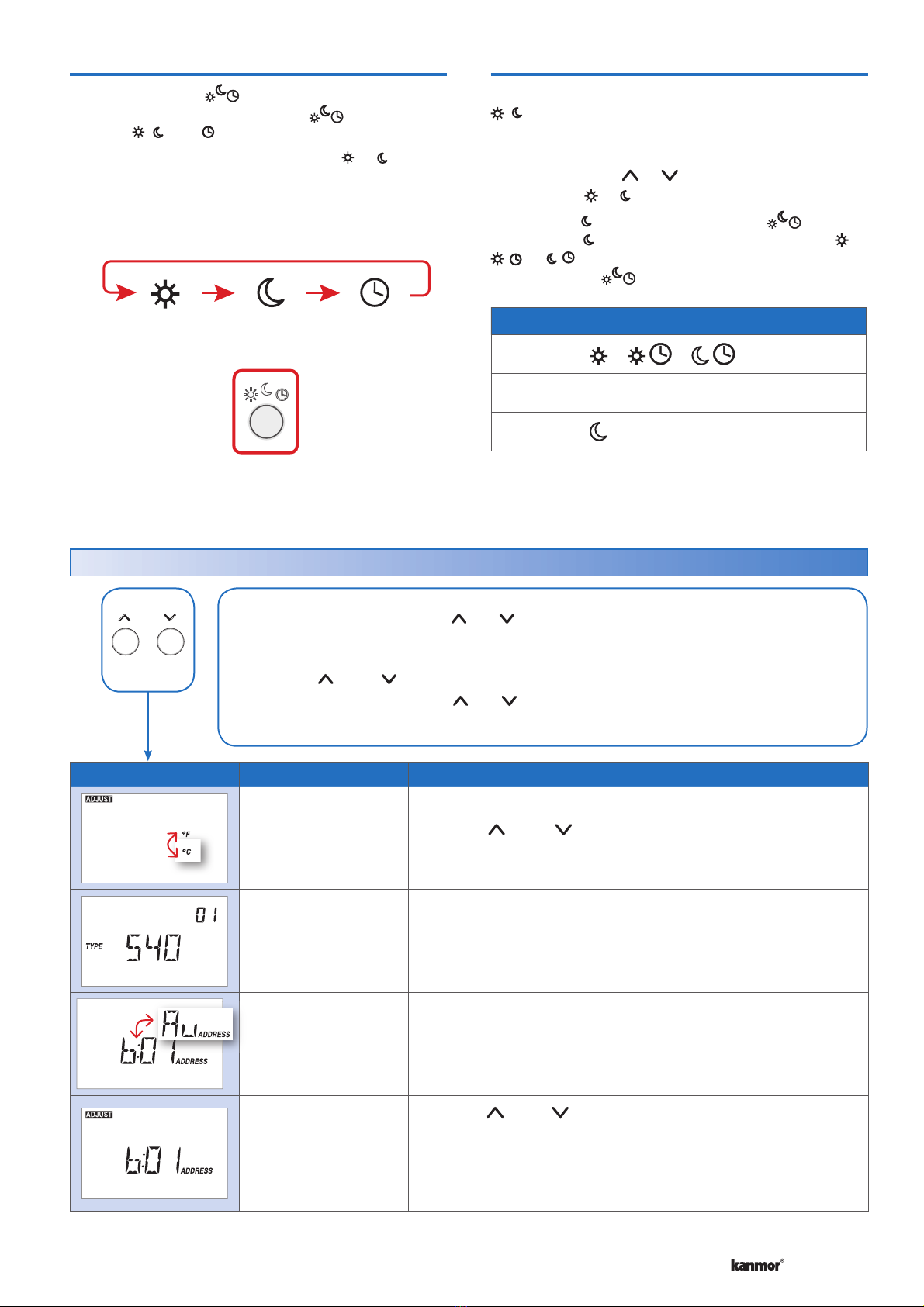
Exercising
When connected to a tN4 System Control, and switch
setting 4 is set to hydronic, the thermostat exercises the
heat relay for 10 seconds every 3 days. Exercising helps
prevent zone valves or zone pumps from failing due to
precipitate buildup. During exercising, the thermostat
shows “TEST” on the display.
Zone Test
The installer can use the tN4 System Control to select
one zone at a time to turn on. This is called a zone test.
The zone test eliminates the need to for the installer to
walk to the thermostat and turn up the heat in order for
the zone to turn on and activate the corresponding zone
pump or zone valve. This is useful for verifying that the
electrical wiring is correct.
If the thermostat address is selected on the tN4 System
Control, the thermostat display will show “ZONE TEST
On”. If not selected, the thermostat display will show
“ZONE TEST OFF”. The Zone Test is only available on
this thermostat when switch setting 4 is set to hydronic.
Max Heat
The installer can use the tN4 System Control to turn
on all heating zones and at the same time operate the
heating equipment at 100% output within temperature
limits. The thermostat operates at the temperature
setting + 5°F (3°C). This is called max heat. Max heat
can be manually stopped or it can last for 24 hours and
automatically resume normal operation. Max heat is useful
in order to quickly heat up the building in order to cure
concrete, dry sheet rock, or dry paint quickly.
The thermostat display will show “MAX HEAT” while in the
max heat operation. The Max Heat is only available on
this thermostat when switch setting 4 is set to hydronic.
Flushing
If the thermostat is connected to a tN4 System Control
with the Flushing feature turned on and switch setting 4 is set to hydronic, then the thermostat display will add the
“FLUSH” icon for the duration of the flushing operation.
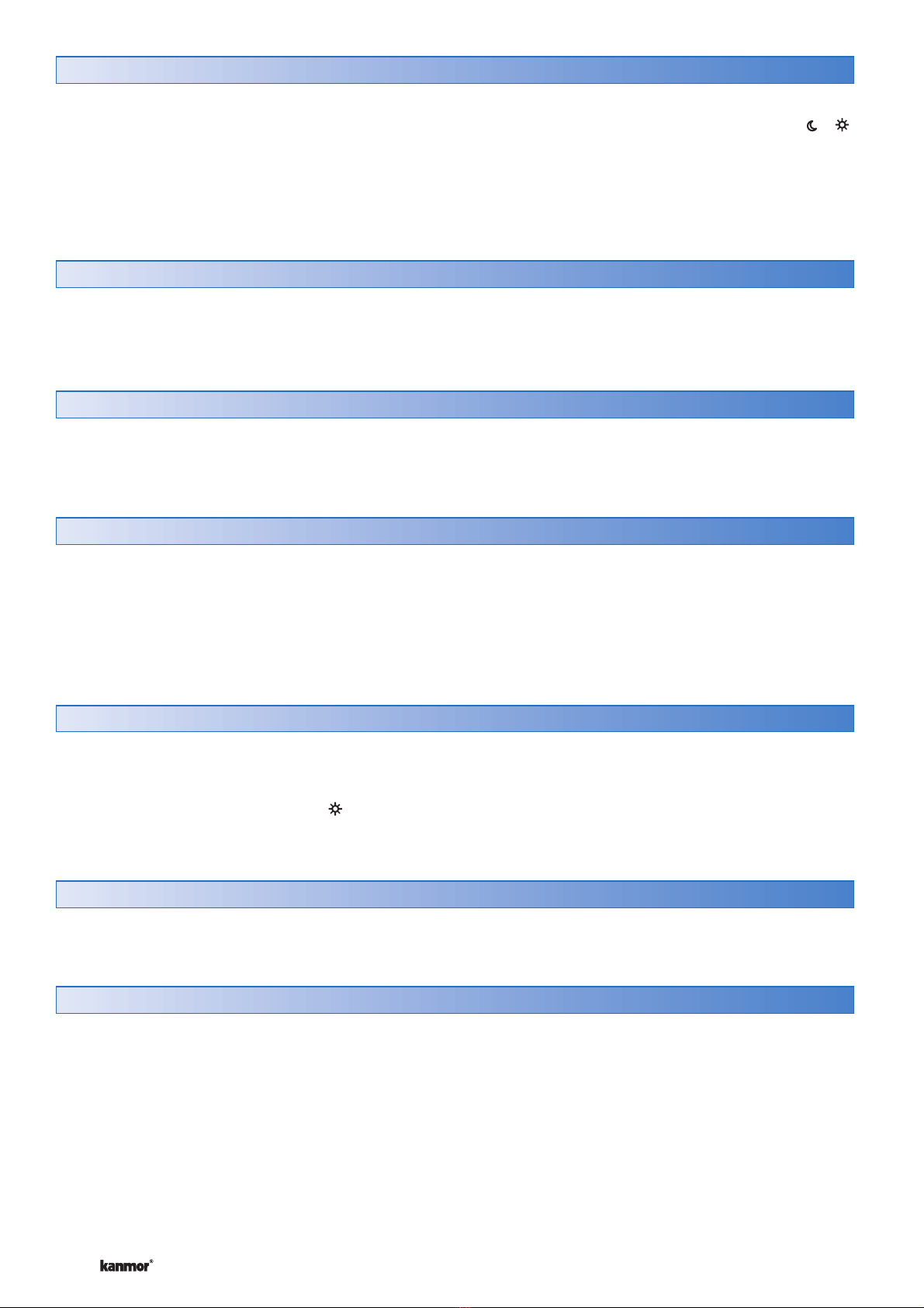
tN4 Address
When the thermostat uses the tN4 bus to communicate
to other devices, the thermostat is automatically assigned
an address.
The address includes the tN4 bus number and a device
number. The tN4 bus number is only shown when connected
to a tN4 System Control. The tN4 bus numbers available
are Boiler, 1, 2, 3, etc. The device number can range from
1 to 24. When the thermostat is not connected to a tN4
bus, the address is not available.
When the thermostat has an automatically set address, the
address number and “Au” will toggle back and forth.
Note: Keep track of manually set tN4 addresses. When
a tN4 address is manually set, tN4 thermostats using
the auto address setting will automatically be assigned
new addresses.
If two thermostats are manually set to the same address, an
error message will appear. The error remains until one of the
addresses is manually changed to a vacant address.

11 of 12 © 2008 D540e - 02/08
Error Messages (1 of 1)
Error Message Description
CONTROL ERROR
The thermostat was unable to correctly read settings from memory and has reloaded
the factory defaults settings. The thermostat does not operate the heating, cooling, or
the fan while this error message is present.
Error clears once all adjust menu settings have been checked.
To enter the installer adjust menu, press Mode, , and buttons at the same time.
Press the Mode button to advance to the next setting.
BUS ERROR
The tN4 communication bus has either an open or a short circuit. The result is that there
are no communications. Check for loose wires. Check for short circuits between the tN4
and C wires. Check for correct polarity between the C and R wires.
Error clears automatically once wiring fault has been corrected.
If the thermostat is intentionally removed from the tN4 bus, press the and buttons
together to clear the error message.
DEVICE LIMIT
The number of devices on the tN4 bus has exceeded 24. Devices include tN4 Thermostats,
and tN4 Setpoint Controls. The device count must be lowered to 24 or less. If possible,
move devices to other tN4 busses.
Error clears automatically once the number of devices on the tN4 bus is at 24 or
lower.
ADDRESS ERROR
This thermostat and another device have been manually given the same tN4 address.
Error clears automatically once this thermostat is given a new manually set address or
if the thermostat is set to automatic addressing.
ROOM SENSOR SHORT CIRCUIT
The built-in air temperature sensor has a short circuit fault.
This error cannot be field repaired.
Contact your wholesaler or kanmor sales representative for details on the repair
procedures.
ROOM SENSOR OPEN CIRCUIT
The built-in air temperature sensor has an open circuit fault.
This error cannot be field repaired.
Contact your wholesaler or kanmor sales representative for details on the repair
procedures.
COOL MASTER ERROR
Switch setting number 3 has been selected to become a cool group master of group
number 1, and another cool group master has been detected with the same group
number.
The cooling system will not operate while this error message is present.
Error clears once either the other cool group master changes its group number or switch
setting number 3 is set to none (On position).
Error Messages

kanmor Control Systems Ltd.
5100 Silver Star Road
Vernon, B.C. CANADA V1B 3K4
250-545-2693 Fax. 250-549-4349
Web Site: www.kanmor.com
12 of 12
© 2008 by kanmor Control Systems Ltd. Used with permission.
kanmor trademark is used under license.
All specifications are subject to change without notice.
Printed in Canada. D540e - 02/08
The thermostats’s exterior can be cleaned using a damp cloth. Moisten the cloth with water and wring out prior to wiping
the control. Do not use solvents or cleaning solutions.
Cleaning the Thermostat
Limited Warranty and Product Return Procedure
Limited Warranty The liability of kanmor under this
warranty is limited. The Purchaser, by taking receipt
of any kanmor product (“Product”), acknowledges
the terms of the Limited Warranty in effect at the time
of such Product sale and acknowledges that it has
read and understands same.
The kanmor Limited Warranty to the Purchaser on the
Products sold hereunder is a manufacturer’s pass-
through warranty which the Purchaser is authorized
to pass through to its customers. Under the Limited
Warranty, each kanmor Product is warranted against
defects in workmanship and materials if the Product
is installed and used in compliance with kanmor’s
instructions, ordinary wear and tear excepted. The
pass-through warranty period is for a period of twenty-
four (24) months from the production date if the Prod-
uct is not installed during that period, or twelve (12)
months from the documented date of installation if
installed within twenty-four (24) months from the pro-
duction date.
The liability of kanmor under the Limited Warranty shall
be limited to, at kanmor’s sole discretion: the cost of parts
and labor provided by kanmor to repair defects in mate-
rials and / or workmanship of the defective product; or
to the exchange of the defective product for a warranty
replacement product; or to the granting of credit limited to
the original cost of the defective product, and such repair,
exchange or credit shall be the sole remedy available
from kanmor, and, without limiting the foregoing in any
way, kanmor is not responsible, in contract, tort or strict
product liability, for any other losses, costs, expenses,
inconveniences, or damages, whether direct, indirect,
special, secondary, incidental or consequential, arising
from ownership or use of the product, or from defects in
workmanship or materials, including any liability for fun-
damental breach of contract.
The pass-through Limited Warranty applies only to those
defective Products returned to kanmor during the war-
ranty period. This Limited Warranty does not cover the
cost of the parts or labor to remove or transport the defec-
tive Product, or to reinstall the repaired or replacement
Product, all such costs and expenses being subject to
Purchaser’s agreement and warranty with its customers.
Any representations or warranties about the Products
made by Purchaser to its customers which are different
from or in excess of the kanmor Limited Warranty are
the Purchaser’s sole responsibility and obligation. Pur-
chaser shall indemnify and hold kanmor harmless from
and against any and all claims, liabilities and damages
of any kind or nature which arise out of or are related to
any such representations or warranties by Purchaser to
its customers.
The pass-through Limited Warranty does not apply if the
returned Product has been damaged by negligence by
persons other than kanmor, accident, fire, Act of God,
abuse or misuse; or has been damaged by modifications,
alterations or attachments made subsequent to purchase
which have not been authorized by kanmor; or if the Prod-
uct was not installed in compliance with kanmor’s instruc-
tions and / or the local codes and ordinances; or if due to
defective installation of the Product; or if the Product was
not used in compliance with kanmor’s instructions.
THIS WARRANTY IS IN LIEU OF ALL OTHER WAR-
RANTIES, EXPRESS OR IMPLIED, WHICH THE GOV-
ERNING LAW ALLOWS PARTIES TO CONTRACTU-
ALLY EXCLUDE, INCLUDING, WITHOUT LIMITATION,
IMPLIED WARRANTIES OF MERCHANTABILITY AND
FITNESS FOR A PARTICULAR PURPOSE, DURABIL-
ITY OR DESCRIPTION OF THE PRODUCT, ITS NON-
INFRINGEMENT OF ANY RELEVANT PATENTS OR
TRADEMARKS, AND ITS COMPLIANCE WITH OR NON-
VIOLATION OF ANY APPLICABLE ENVIRONMENTAL,
HEALTH OR SAFETY LEGISLATION; THE TERM OF
ANY OTHER WARRANTY NOT HEREBY CONTRACTU-
ALLY EXCLUDED IS LIMITED SUCH THAT IT SHALL
NOT EXTEND BEYOND TWENTY-FOUR (24) MONTHS
FROM THE PRODUCTION DATE, TO THE EXTENT
THAT SUCH LIMITATION IS ALLOWED BY THE GOV-
ERNING LAW.
Product Warranty Return Procedure All Products that
are believed to have defects in workmanship or materi-
als must be returned, together with a written description
of the defect, to the kanmor Representative assigned to
the territory in which such Product is located. If kanmor
receives an inquiry from someone other than a kanmor
Representative, including an inquiry from Purchaser (if
not a kanmor Representative) or Purchaser’s customers,
regarding a potential warranty claim, kanmor’s sole obli-
gation shall be to provide the address and other contact
information regarding the appropriate Representative.
Table of contents
Other Kanmor Thermostat manuals
Popular Thermostat manuals by other brands

Vive Comfort
Vive Comfort TP-S-755 Operation manual

Automation Correct
Automation Correct Coal-trol Digital TS2BL quick start guide

Protherm
Protherm Exacontrol 1 Operating installations

Nibe
Nibe RMU 40 Installer manual

Delta Controls
Delta Controls BACstat II Series Application guide

Heatmiser
Heatmiser DT-ETS WiFi RF manual