Alare Remiga 2 User manual

Alare
Owner’s manual
Remiga 2
loudspeaker system


Alare is a trademark of Audia snc - Italy
Alare
Dear Customer,
We would like to thank you for choosing a pair of Alare speakers. Before
connecting them to the amplifier and in order to reach the best result, please
read this handbook. Remiga 2 loudspeakers are designed to immediately meet
our customers’ highest expectations. In case of doubt, further information about
installation and listening room needs can be asked your dealer technical staff or
directly at the mail address info@alare-labs.com.
3

A
B
F
E
D
C
4
Accessories
Accessory box (one box each loudspeakers pair) contains following items:
• A) n. 4 jumpers for single wiring connection.
• B) n. 8 steel leveling spikes.
• C) n. 8 steel floor protection discs.
• D) n. 8 steel tightening knobs.
• E) n. 1 T shaped Allen wrench.
• F) n. 1 bubble level.
• n. 1 gloves pair (not shown).
• this manual.

Warranty
Alare warrants materials, workmanship and proper functioning for a period of three years. The Ital-
ian warranty is valid from the purchase date shown on the receipt and only in Italy. Unauthorized
dismantling of the product will render this warranty void. Alare reserves the right to make changes
in design and improvements upon its products without necessarily assuming an obligation to ret-
rofit such changes upon previously manufactured models. Alare shall in no event be obligated for
any incidental or consequential damages as a result of any defect or any warranty claim, whether
expressed or implied. Any replacement of parts not covered by the warranty will be charged to the
customer. Any speaker requiring repairs must be taken to the retailer in its original packaging for
delivery to our offices or authorized service center with a description of the defect. If shipping is
required, such costs are charged to the client. For all foreign markets, the Alare local distributor is
responsible for establishing any and all rules governing warranty in accordance with the rules and
regulations that apply in each country. This includes length of warranty, location where repairs may
be effected, costs, if any, and conditions pertinent to fulfilling the conditions of warranty.
Unpacking
• Due to package weight, it’s advisable to open the packaging as close to the final location as
possible.
• Do not insert any blade, just remove clamps by hand after lock screws are removed.
• Do not wear metal accessories (as watches, rings) in order to avoid scratching loudspeaker
finishes. The same care must be taken in order to protect the loudspeaker from any metal ele-
ments present on the clothes you are wearing (as rivets, zippers or buttons).
Instructions for first unpacking are indicated outside the wooden crating.
We show them again for future packing and unpacking operations.
Safety informations
• Use one of the connection diagrams contained in this instruction manual. We strongly advice
against connecting two or more loudspeakers in parallel. This can damage your amplifier.
• Avoid staying near the loudspeakers while the audio system is operating at high volume. This
can cause permanent damage to your hearing.
• The speakers generate an electromagnetic field that is harmless to humans and pets, but can
compromise the proper functionality of some electronic equipment when placed in close prox-
imity.
• Do not place connection cables in close proximity to electrical power cables. This can cause
humming noise.
• Remiga 2 loudspeaker system is intended for household use. They must not be used for high
volume and continuous sound distribution as sound reinforcement. In this case, signal intensity
is not compatible with correct operation of the system.
55
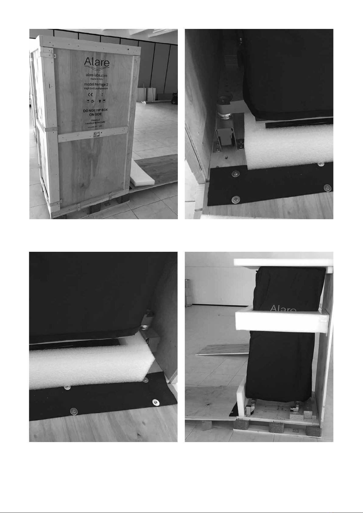
Remove wooden top and top foam pad. Locate
front panel and open it. Two or more people
needed.
Remove accessories box and its foam protection.
Front panel is joined to crating by a nylon strap.
Attention, other wooden panels are free
when clamps are removed.
Remove side and rear panels and foam pads.
Attention, wooden panels are free when
clamps are removed.
6
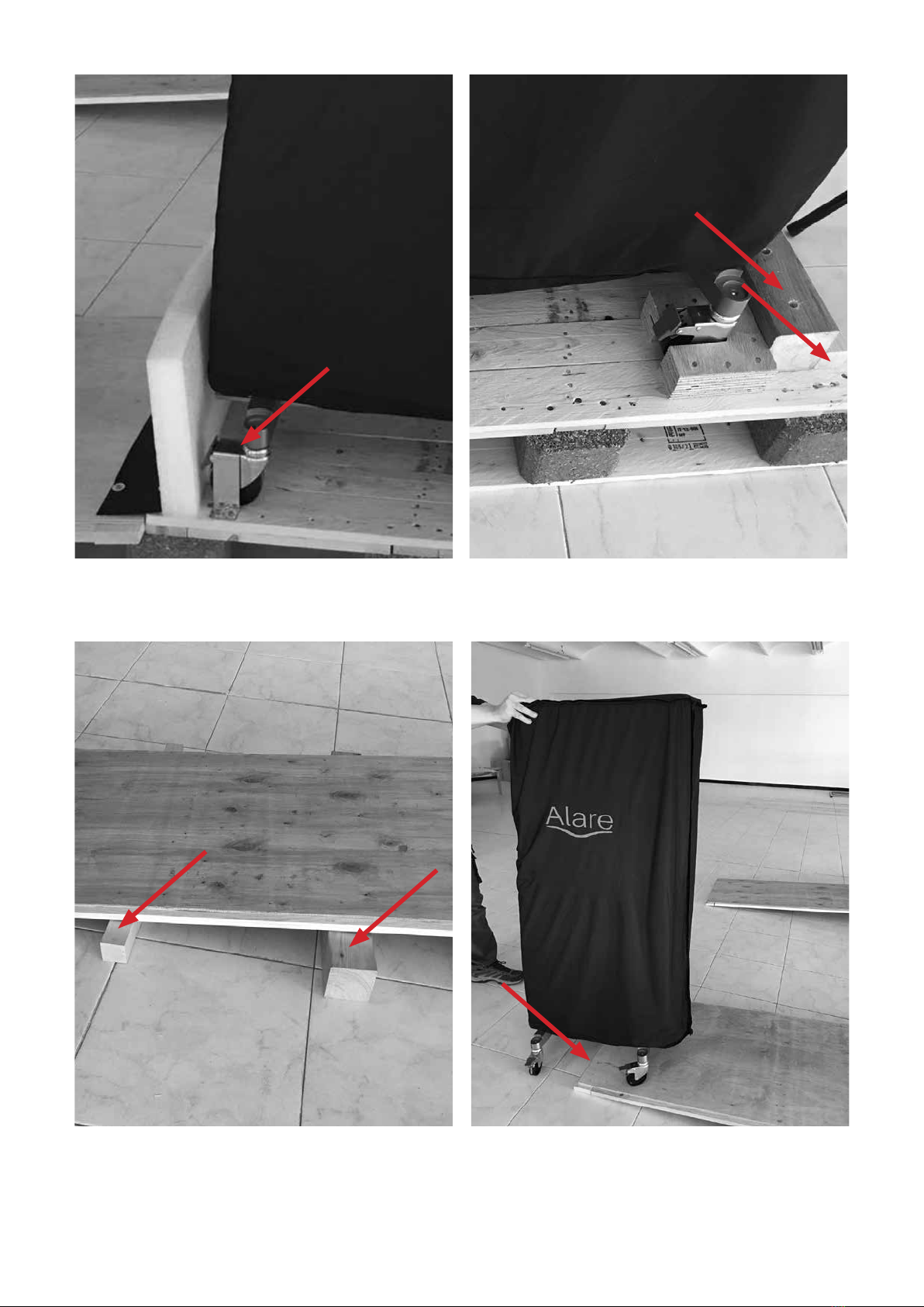
Remove metal clamps from front wheels. Don’t
release wheels brakes off.
Put wooden blocks under inclined panel as in
picture in order to avoid base bending.
Unscrew the four wooden blocks behind rear
wheels.
Release all brakes off and carefully move speaker
down the crating. Be careful on edge step. Two
or more people needed.
7
When in place, activate brakes on all wheels
and tilt speaker pivoting it on a side wheel pair.
Two or more people needed.
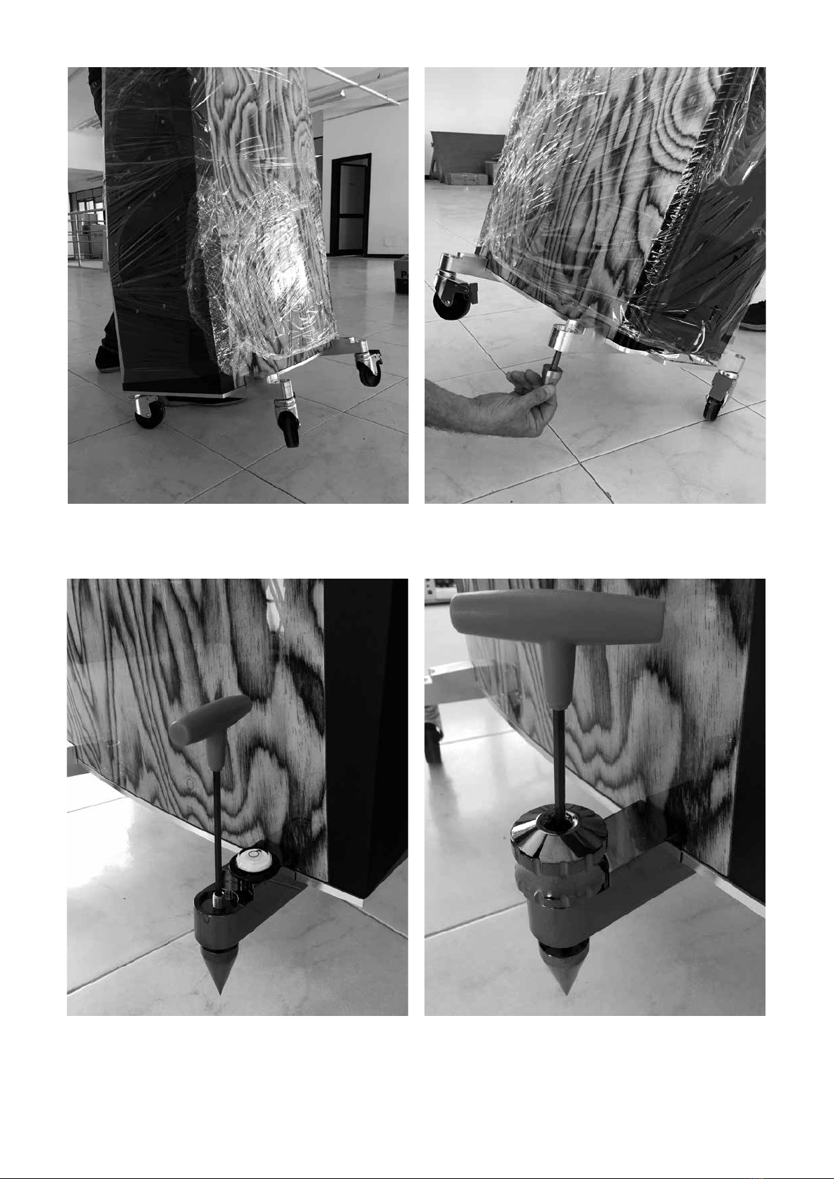
Once speaker is in place, level it acting on
spikes with provided T Allen wrench.
Unscrew the floating pair of wheels and sub-
stitute them with spikes at maximum thread
length. Repeat this procedure on the other side.
Make stiff speaker standing inserting knobs and
tightening them. It is always possible to tune lev-
eling without removing knob, just loosening it.
8
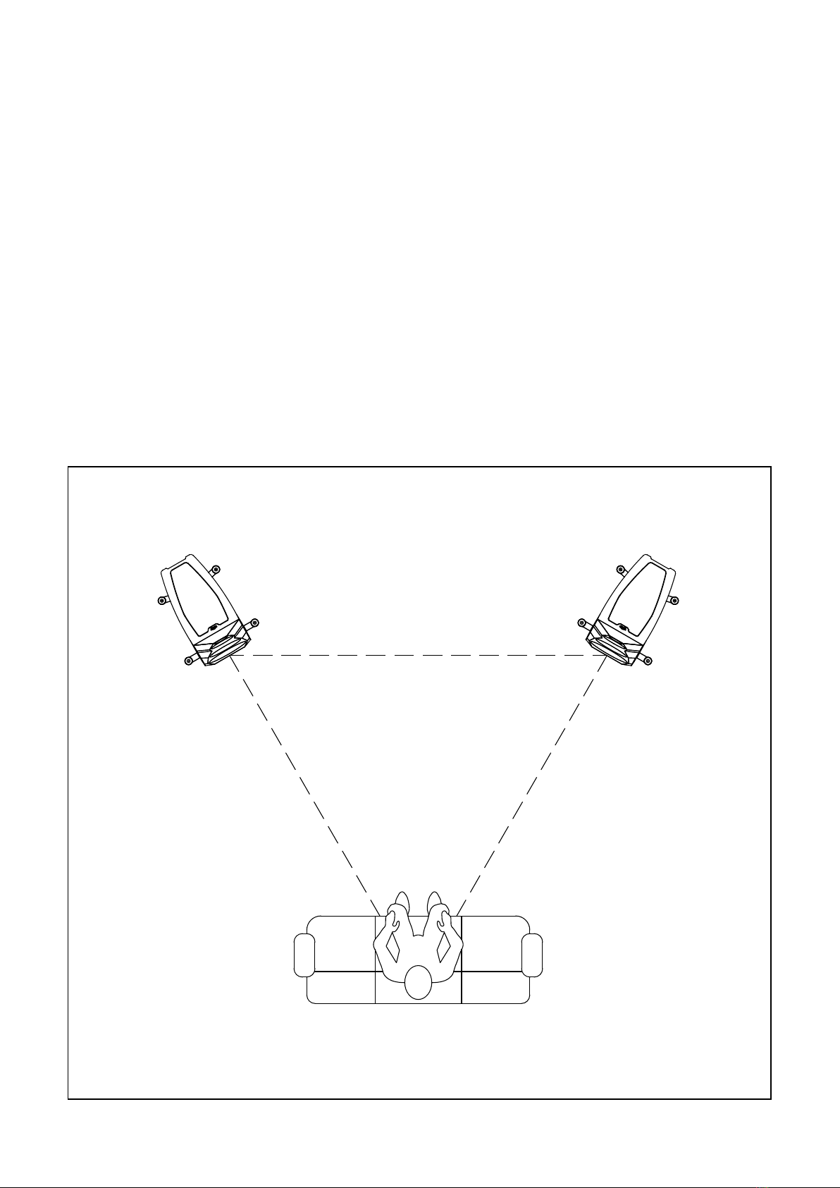
Positioning
Loudspeakers positioning can affect the entire audio system performance in different ways.
Rooms with irregular shape can improve the bass response since they limit the formation of stand-
ing waves. From this point of view, a cube shaped room is the worse case for poor bass frequencies
performances.
The presence of carpets and curtains positively affect the acoustics of the environment, contribut-
ing to the absorption of the first reflections and the lowering the total time of reverberation.
There are no fixed and universally applicable rules for every environment. Nevertheless, a good
approach is to start by using the equilateral triangle rule, that is that speakers and listener are posi-
tioned in proximity of the vertices of the triangle. Loudspeakers should converge toward the listen-
ing position in order to reach the best stereophonic configuration. This is to be considered just the
starting point, little adjustments of the loudspeakers tilting angle can improve the focus of stereo-
phonic image in different listening rooms.
Anyway, it is recommended to position the two loudspeakers away from the corners of the room,
and at a distance of at least 1.5 m from the back wall and at least 2.5 meters apart from each other.
The listening point should be at a height between 0.9 and 1.1 meters off the ground.
9
At least 2.5 m

Cleaning and maintenance
The loudspeakers do not require any particular maintenance operations, just general periodic
cleaning. In order to preserve the loudspeakers finish, cover them with the supplied cover, espe-
cially if the loudspeakers are not expected to be used for an extended period of time.
Do not use products like waxes or detergents to clean the wood parts, as these could stain or
damage the finish of speaker. Do not use aggressive chemical products such as acetone, acids,
abrasive agents, strong de-greasers or alcohol. It is recommended to use a soft brush to eliminate
any dust that may have accumulated on the cabinet, the front panels, and the loudspeakers them-
selves, taking care not to damage the drivers membranes. Never try to remove metal grilles from
midrange e tweeter drivers. It is recommended to use a slightly moistened soft cloth. We recom-
mend positioning the loudspeakers away from heat sources or windows, above all during the sum-
mer months. Avoid exposing the loudspeakers to direct sunlight. These measures will help you to
keep your loudspeakers perfectly for years to come.
10
Right speaker Left speaker
Connections
After the loudspeakers have been positioned, they can be connected. Refer to the illustrations be-
low.
The loudspeaker connection terminals allow you to connect cables terminated with stripped ca-
ble, forks or banana plugs.
A supplied high quality jumpers set allows you single wiring connection.
If you choose bi-wiring connection, these jumpers have to be removed.
Proper tightening and periodic verification of the terminals will help to obtain and maintain optimal
performance.
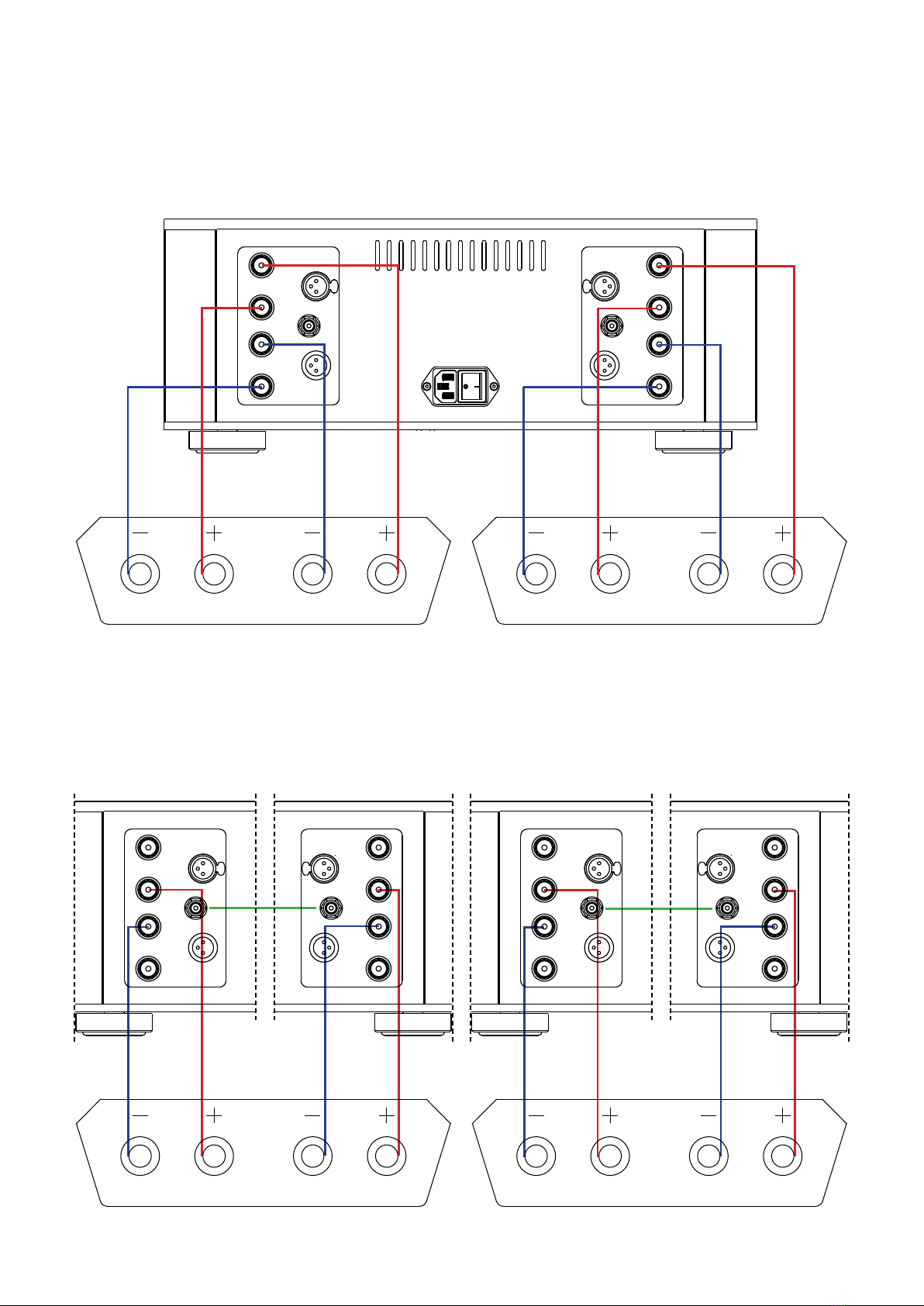
Single wiring connection
It consists in driving loudspeakers with a single stereo amplifier, or with a pair of monophonic am-
plifiers, using only one bipolar power cable for each channel. Complete the connection as shown
in the following illustration. Use the provided jumpers.
OUTPUT
OUTPUT
-
- -
-
+
+
+
+
RCA RCA
RIGHT CHANNEL LEFT CHANNEL
XLR XLR
XLR XLR
Low Md-Hi Low Md-Hi
11
Bi-wiring connection
This scheme allows the bipolar power cables, to be connected to the “Low” sections and the “Md-
Hi” sections of the loudspeakers, to be duplicated. It consists in driving the loudspeakers with a sin-
gle stereo amplifier, or with a pair of monophonic amplifiers, using separate bipolar power cables
for each input section of the loudspeaker. No jumper needed.
Bi-amping connection
This scheme allows the amplifiers to be connected to the “Low” sections and the “Md-Hi” sections
of the loudspeakers to be different. Loudspeakers are run with two distinct stereo amplifiers, or with
two pairs of monophonic amplifiers, using separate bipolar power cables for each input section of
the loudspeaker. No jumper needed. Input signal for right/left amplifiers pair is common.
Right speaker Left speaker
OUTPUT
OUTPUT
-
- -
-
+
+
+
+
RCA RCA
RIGHT CHANNEL LEFT CHANNEL
XLR XLR
XLR XLR
Low Md-Hi Low Md-Hi
Right speaker
Right amps Left amps
Left speaker
OUTPUT
OUTPUT
-
-
-
-
+
+
+
+
RCA
RCA
RIGHT CHANNEL
LEFT CHANNEL
XLR
XLR
XLR
XLR
OUTPUT
OUTPUT
-
-
-
-
+
+
+
+
RCA
RCA
RIGHT CHANNEL
LEFT CHANNEL
XLR
XLR
XLR
XLR
OUTPUT
OUTPUT
-
-
-
-
+
+
+
+
RCA
RCA
RIGHT CHANNEL
LEFT CHANNEL
XLR
XLR
XLR
XLR
OUTPUT
OUTPUT
-
-
-
-
+
+
+
+
RCA
RCA
RIGHT CHANNEL
LEFT CHANNEL
XLR
XLR
XLR
XLR
Low Md-Hi Low Md-Hi
12
Technical data
Sistem: three way floor standing speaker.
Bass loading: tapered transmission line.
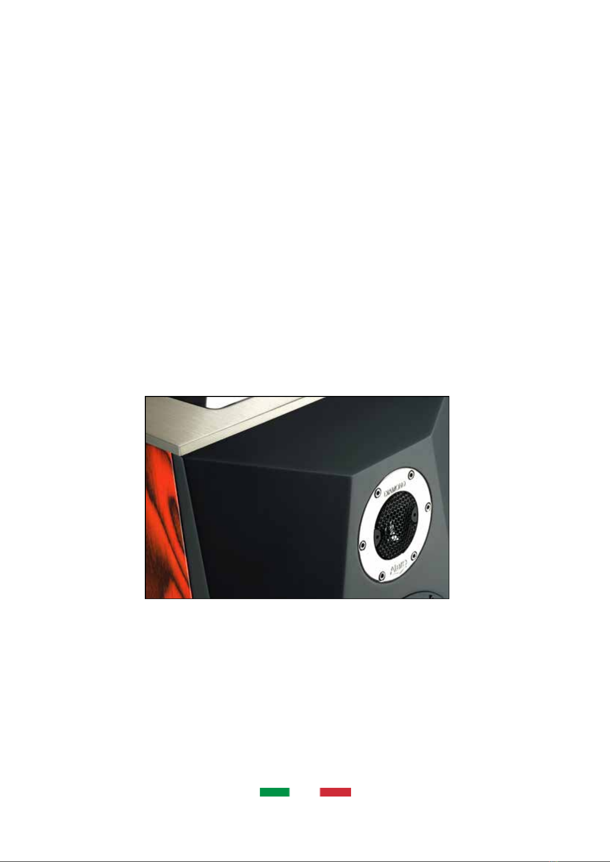
Woofers: 1 x 10” (250mm), 1 x 8” (200 mm) carbon sandwich cone.
Midrange: 7” (170 mm) pure ceramic membrane.
Tweeter: 1.2” (30 mm) pure diamond membrane.
Crossover: silver plated solid copper point-to-point wiring.
Wiring: special silver plated copper.
Impedance: nominal 4 Ohm (minimum 3.3 Ohm).
Sensitivity: 86 dB (2.83V/1m one driven).
Frequency response: 32Hz – 30kHz (0 – 3dB).
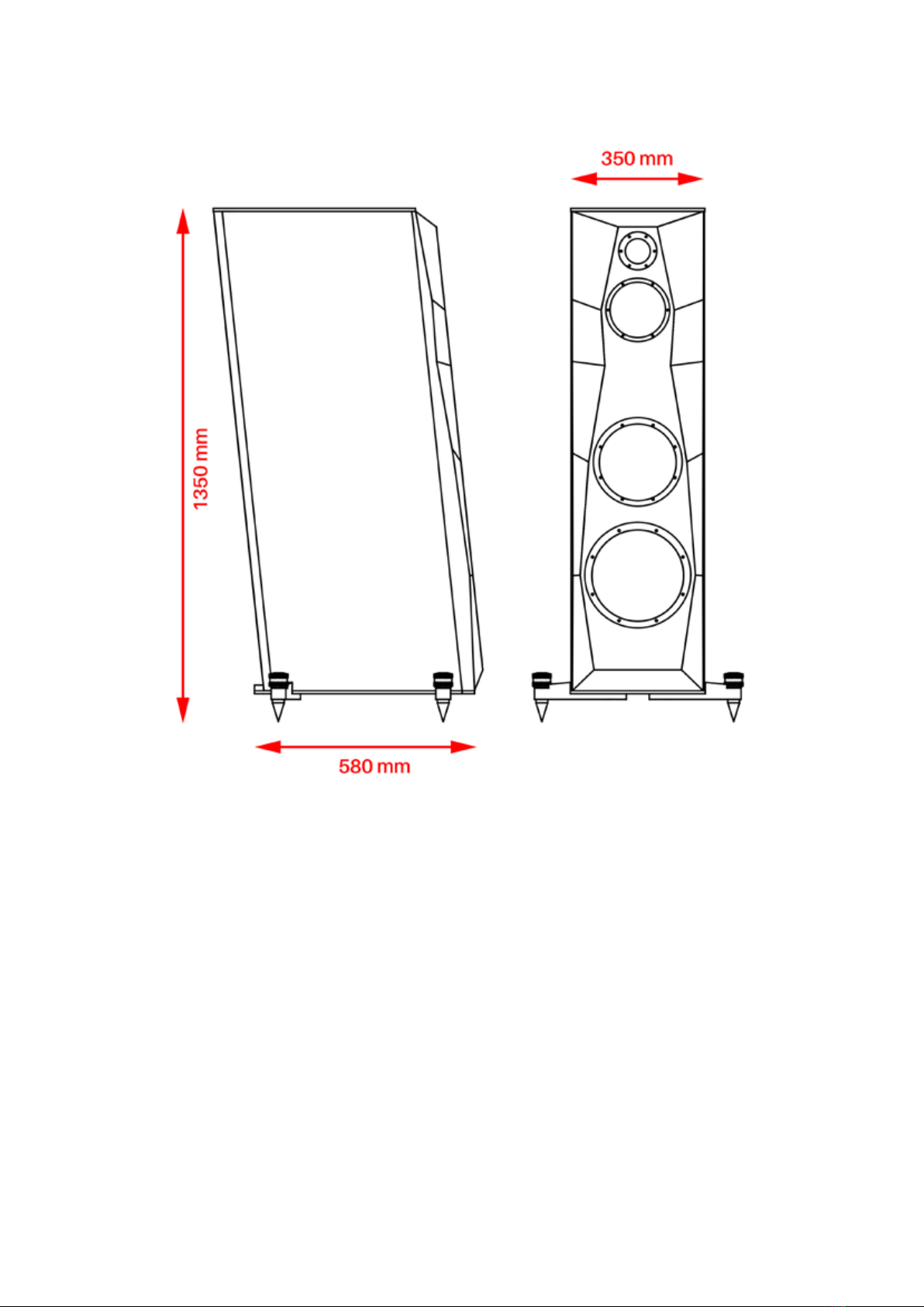
Dimensions: 135 x 35 x 58 cm.
Weight: 120 kg (each, without crating).

13
Notes

14
Alare is a trademark of
Audia snc
Via Alfio Flores, 7
00053 Civitavecchia
(RM) - Italy
www.alare-labs.com
info@alare-labs.com
Made in Italy
Alare

Eng. rel. 1.0
alare-labs.com
Table of contents


