Albany RapidRoll 670 User manual

USER MANUAL
RAPID-ROLL® DOOR OWNER’S MANUAL
Model 670 & Model 570
975-A OLD NORCROSS ROAD
LAWRENCEVILLE, GA 30045
(770) 338-5000 TEL
(770) 338-5034 FAX
(877) 925-2468 TOLL FREE

Part Number 6410T0006 Version 4/22/2010
2
Architectural Drawing of the 570 & 670 Rapid Roll Door
Models

Part Number 6410T0006 Version 4/22/2010
3
Table of Contents
STATEMENT OF WARRANTY..................................................................Error! Bookmark not defined.
SAFETY PRACTICES ....................................................................................................................................5
PACKING LIST...............................................................................................................................................6
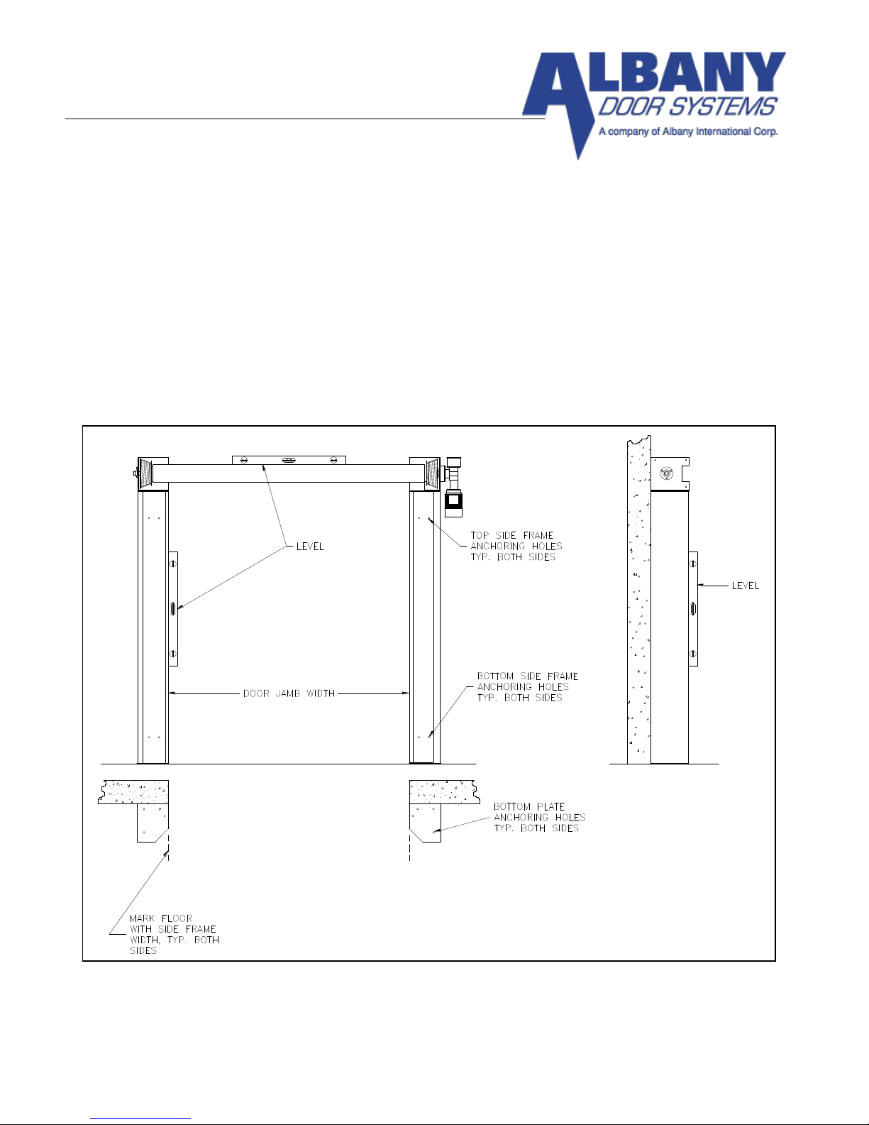
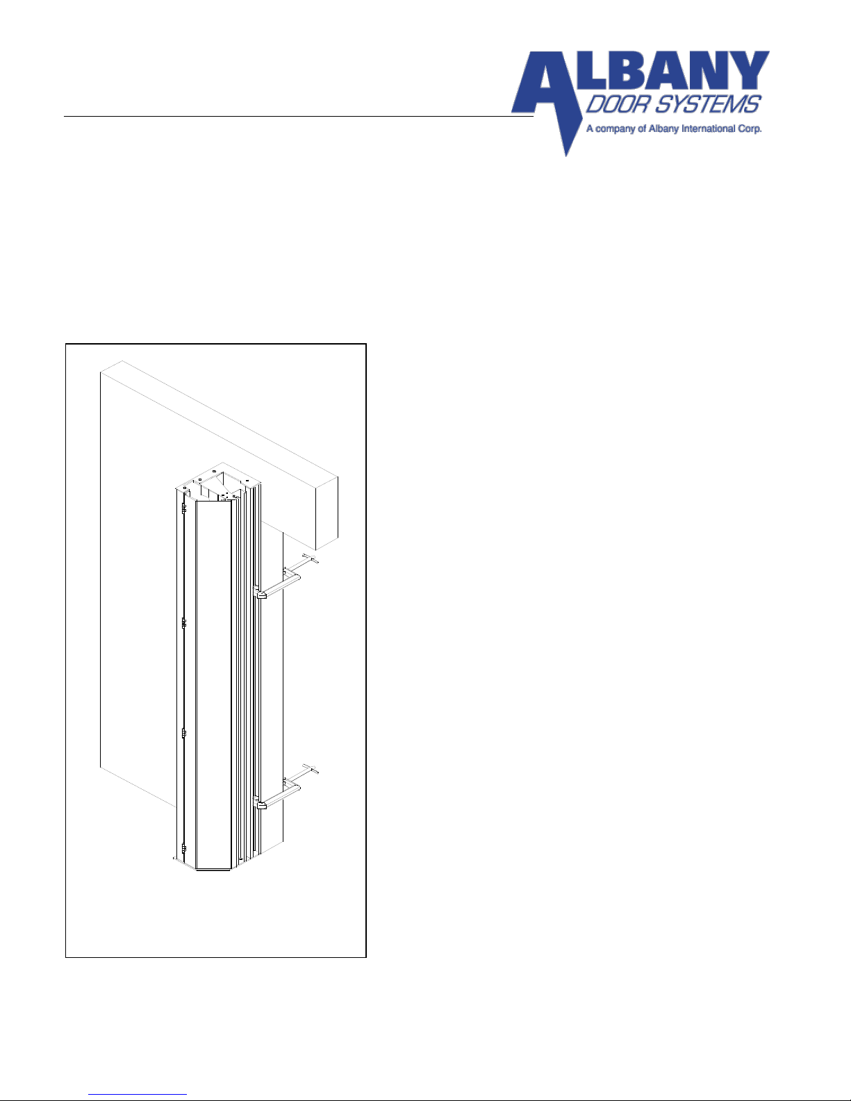
RAPID ROLL® MODEL 570/670 INSTALLATION......................................................................................7
FRAME AND GENERAL INSTALLATION.............................................................................................7
COUNTER-BALANCE SPRING INSTALLATION AND CABLE ROUTING..........................................12
STANDARD BOTTOM BEAM................................................................................................................12
BOTTOM BEAM EQUIPPED WITH SELF-REPAIRING DEVICE™ OPTION. ..................................16
BOTTOM BEAM EQUIPPED WITH RAPID RESET™ OPTION. (Model 670 Only) ..........................19
SPRING TENSIONING AND DOOR BALANCE.......................................................................................19
MAINTENANCE AND INSPECTION.........................................................................................................22
DAILY INSPECTION................................................................................................................................22
QUARTERLY INSPECTION....................................................................................................................22
RAPID ROLL DOOR 570/670 MAINTENANCE CHECKLIST ............................................................23
INSPECTIONS...........................................................................................................................................24
PULLEY INSPECTION.............................................................................................................................26
CABLE DRUM INSPECTION..................................................................................................................26
SELF-REPAIRING DEVICE™ BOTTOM BEAM TYPE .......................................................................26
BRAKE ADJUSTMENT...........................................................................................................................27
OPTION INSTALLATION AND OPERATION ..........................................................................................28
CHAIN DRIVE INSTALLATION.............................................................................................................28
CONTACTLESS SAFETY EDGE™ (C.S.E.) .............................................................................................30
MECHANICAL INSTALLATION............................................................................................................30
ELECTRICAL INSTALLATION..................................................................................................................31
ADJUSTMENTS .......................................................................................................................................32
FULL ROLL COVER & MOTOR COVER INSTALLATION ....................................................................34
FULL VISION PANEL™REPLACEMENT .................................................................................................35
MANUAL DISENGAGEMENT ..................................................................................................................40
MANUAL DISENGAGEMENT ...................................................................................................................41
MANUAL HOIST INSTALLATION............................................................................................................43
MANUAL HOIST WITH DISCONNECT INSTALLATION .....................................................................44
WINDBAR INSTALLATION.......................................................................................................................46
STRAPPED WINDBAR INSTALLATION..............................................................................................46
STRAPLESS WINDBAR INSTALLATION ................................................................................................49
AIR CIRCULATION SYSTEM ....................................................................................................................51
MECHANICAL INSTALLATION............................................................................................................51
ELECTRICAL INSTALLATION..............................................................................................................52
AIR FLOW ADJUSTMENTS ...................................................................................................................53
RAPID ROLL®MODEL 570/670 INSTALLATION CHECKLIST.............................................................55

STATEMENT OF WARRANTY
UltraFabric, RapidRoll 230, RapidRoll 355, RapidRoll 670
High Speed Doors
ONE-YEAR WARRANTY ON MECHANICAL AND ELECTRICAL COMPONENTS
AlbanyDoor Systems warrants to the original owner of the door that the mechanical and electrical components will be free
from defects in material and workmanship for a period of one (1) year from the date of shipment. Vinyl fabricmaterial,mesh
screen material and transparent (PVC) polyvinyl chloride material is warranted for one (1) year. Two (2) plypanel materialis
warranted for two (2) years and three (3) ply panel material is warranted for three (3) years.
Only defects brought to the attention of AlbanyDoor Systems during the warranty period will be covered by this warranty.
Albany Door Systems will replace component parts covered by this warranty, which are found to be defective upon
inspection by an AlbanyDoor Systems representative. Installation or use of parts other than those authorized by Albany
Door Systems will void this warranty.
PARTS AND ASSEMBLIES sold separately by Albany Door Systems that fail due to defects in material or workmanship
within ninety(90) days from the date of shipment will be replaced under warranty provided installation has been carried out
in accordance with all AlbanyDoor Systems procedures. This warranty is limited to providing a replacement partonly.This
warranty does not cover freight, special charges, or any costs associated with the installation of the replacement part.
This warranty covers material failure under normal wear conditions; it does not cover damage caused by collision or
other abuse of the product. Adjustments made to the control panel or to the mechanical operation of the door without
the authorization of Albany Door Systems will void this warranty. Any changes made to product configuration without
the express written approval from Albany Door Systems may null and void this warranty.
Albany Door Systems’ obligations under this warranty are limited to repairing or replacing the defective part including
labor and Albany Door Systems shall not be responsible for any other losses or damages due to the operation of any
door or parts covered by this warranty. Warranty parts will be shipped regular ground freight at the expense of Albany
Door Systems.
This warranty shall be void in its entirety if the failure of any product shall be caused by any installation, operation, or
maintenance of the product which does not conform with the requirements set forth by the seller in the applicable
product manuals or is in the result of any cause other than a defect in the material or workmanship of the product.
No other oral or written representations made by Albany Door Systems or its agents are a part of this warranty unless
specifically set forth in writing by an authorized Albany Door Systems official.
THE ABOVE SET FORTH WARRANTY IS SELLER'S SOLE WARRANTY. SELLER MAKES NO OTHER WARRANTY OF
ANY KIND WHATSOEVER, EXPRESSED OR IMPLIED; AND ALL IMPLIED WARRANTIES OF MERCHANTABILITY
AND FITNESS FOR A PARTICULAR PURPOSE WHICH EXCEED THE AFORESTATED OBLIGATION ARE HEREBY
DISCLAIMED BY SELLER AND EXCLUDED FROM THIS AGREEMENT.
Albany Door Systems - A Company of Albany International Corp. All Rights Reserved
1080 Maritime Drive, Port Washington, WI 53074 - 975-A Old Norcross Road, Lawrenceville, Georgia 30045
262-268-9885 or 877-9252468
v4202010

Part Number 6410T0006 Version 4/23/2010
5
SAFETY PRACTICES
WARNING
THOROUGHLY READ THESE SAFETY PRACTICES PRIOR TO INSTALLING, OPERATING, OR
SERVICING A HIGH-SPEED, RAPID ROLL®DOOR. FAILURE TO FOLLOW THESE SAFETY
PRACTICES MAY RESULT IN PROPERTY DAMAGE, PERSONNEL BODILY INJURY, OR
DEATH.
1. Do not operate a Rapid Roll®Door while you are under the influence of drugs or alcohol.
2. Do not use the door if any parts appear to be broken or damaged.
3. Stay clear of the door while it is operating.
4. Keep hands and feet clear of the door at all times.
5. Do not drive through the door opening unless door is completely open.
6. Maintain a clear door opening at all times. Keep the door opening free of any obstructions.
7. Remove power at the fused disconnect during all electrical or mechanical service. OSHA requires a
disconnect to be properly tagged and locked out during all maintenance or service of equipment.
8. All electrical troubleshooting or service must be performed by a qualified electrician or service person
and must meet all applicable local, state, federal, international, and other governing agency codes.
9. USE EXTREME CAUTION when it is necessary to service the control panel while it is energized.
10. If you have any questions, please contact your local Albany service provider for assistance. Otherwise
contact Albany International at 1-877-925-2468 for information on your local distributor.
All bolts, fasteners, and electrical connections must be checked and
tightened while installing the door.

Part Number 6410T0006 Version 4/23/2010
6
PACKING LIST
Before beginning the installation, thoroughly inspect the crate to ensure all necessary components are
there. The following list applies to a standard Model 570/670 door (no optional parts are indicated).
Left Hand and Right Hand Side Frames with attached Covers (2 sets)
Top Roll Assembly with attached Drive Unit (1)
Electrical Control Panel (1)
Reversing Photocells (1 set)
Pressure Switch Enclosure w/ attached Retractile Cord (1 set)
Counter Balance Springs (2)
Cables (2)
Assembly Hardware:
(2) Top pulley brackets
(2) Intermediate pulley brackets
(8) Bolts, axle bearing brackets, 3/8”-16
(4) Locking pins, side frame cover

Part Number 6410T0006 Version 4/23/2010
7
RAPID ROLL® MODEL 570/670 INSTALLATION
FRAME AND GENERAL INSTALLATION
Step 1 Unpack crate and inventory parts, comparing against the packing list in the front of this manual, to
verify all parts are on site.
Step 2 Using a tape measure; determine the actual door width by measuring the width gauge on the top
roll assembly (Figure 1). Apply this measurement to the actual door opening. Mark the floor on each side
of the opening to indicate the inside position of the side frame assemblies.
FIGURE 1

Part Number 6410T0006 Version 4/23/2010
8
Step 3 Verify that the opening is plumb and that the floor slab is level. If they are not, shimming and
adjustments to the side frames must be made to accomplish this during door installation. Refer to
approval drawings for this door to confirm drive side mounting (left or right-hand).
Step 4 Remove side frames from crate (one at a time) and erect them into position against the wall at the
pre-marked locations on the floor.
Step 5 Plumb the side frames and temporarily secure them to the wall using C-clamps. (Figure 2)
Step 6 Using an approved lifting device, place a lifting
strap around the top roll assembly, lift and remove from
shipping crate as indicated by Figure 3. Slide the operator
onto the stub axle, Figure 5a and attach to the top roll
assembly with the supplied hardware. Or it can be added
after the top roll assembly is bolted to the side frames
Raise the top roll assembly into position and lower it
slowly onto the top of both side frames. Using the
supplied 3/8”–16 bolts, fasten the side frame top plates to
axle bearing plates using the three-corner bolt holes
(Figure 4).
NOTE
POSITION THE LIFTING DEVICE AND STRAPS
ACCORDINGLY AS THE DOOR WILL BE HEAVIER
ON THE DRIVE SIDE IF YOU ATTACHED THE
DRIVE BEFORE LIFTING INTO PLACE. DO NOT
REMOVE THE LIFTING DEVICE UNTIL THE
DOOR IS PERMANENTLY ATTACHED TO WALL.
NOTE
THE NEXT STEP INVOLVES INSTALLING THE TOP
PULLEY BRACKETS. PRIOR TO DOING SO,
ENSURE THE DRIVE UNIT IS ATTACHED
(Figures 5A and 5B) AND THE BRAKE IS NOT
RELEASED.
Step 7 In order to allow clearance for installing the top
pulley brackets, the door fabric must be lowered a
maximum of two feet. Tie a rope around the top roll,
leaving approximately two feet of slack.
(Figure 5)
FIGURE 2

Part Number 6410T0006 Version 4/23/2010
9
FIGURE 3
FIGURE 4
FIGURE 5

Part Number 6410T0006 Version 4/23/2010
10
Slide Motor onto
Keyed Stub axle.
Figure 5A
Figure 5B
Attach Limit
sprocket to stub
axle via bolt, bend
tab up to secure.
Attach “L” bracket
mounted on motor
to header assembly

Part Number 6410T0006 Version 4/23/2010
11
Step 8 Cut the plastic straps that are tied around the top roll assembly and bottom beam. Allow the door
curtain to drape down a maximum of two feet.
Step 9 Install the top pulley brackets on both side frames using the four remaining 3/8”-16 bolts and the
two center bolt holes in the side frame top clamping plates. (Figure 4)
Step 10 Release the brake by pulling down on the brake release lever (Figure 6). Rotate the top roll
assembly until the slots in both cable drums are accessible through the openings in the axle bearing
brackets (Figure 7). Reengage the brake by releasing the brake disengagement lever. Both cable drum
slot should have the same orientation. Do not hang the cable straight down when the door is in the full up
position.
FIGURE 4
-
FIGURE 6
FIGURE 6

Part Number 6410T0006 Version 4/23/2010
12
NOTE: the counter balance spring and cable installation section below is divided into two sections
based on the bottom-beam type. Reference the section that is applicable to your installation.
NOTE! : WITH 0-WRAPS THE CABLE DOES NOT HANGS STRAIGHT DOWN
FROM THE CABLE DRUM. IT STILL HAS ¼ TO ½ OF A WRAP ON THE
CABLE DRUM. IT SHOULD NEVER HANG STRAIGHT DOWN FROM THE
CONNECTION POINT TO THE CABLE DRUM.
COUNTER-BALANCE SPRING INSTALLATION AND CABLE ROUTING
STANDARD BOTTOM BEAM
FIGURE 7
Correct
Incorrect

Part Number 6410T0006 Version 4/23/2010
13
A. Starting on one side, install a counter balance spring into one side
frame by hooking the spring tang in the side frame bottom plate
bracket and standing it upright inside the side frame.
B. Each spring has a tag indicating the door serial number, spring
size, number of pre-wraps on cable drums, and spring pre-stretch
distance. Using a tape measure, determine and mark the inside of
the side frame to indicate the pre-stretch point of the spring.
C. Clamp the intermediate pulley bracket in an upright position with
center hole placed at the pre-stretch point (Figure 8).
D. Unroll cables and lay out to full length. Ensure that they are not
twisted and there are no kinks in the cable itself. Starting on one
side (left-hand or right-hand), attach the looped end of the cable
to the cable drum at the attachment point (Figure 7).
E. Starting at the cable drum feed the other end of cable from front
to back going underneath the cable drum and around. Place the
stated number of pre-wraps on the cable drum as indicated on the
spring tag. Ensure the cable is run in the cable grooves, in order,
with none of the grooves being skipped or crossed (Figure 9).
NOTE: WITH 0-WRAPS THE CABLE DOES NOT HANG
STRAIGHT DOWN FROM THE CABLE DRUM. IT STILL
HAS ¼ TO ½ OF A WRAP ON THE CABLE DRUM. IT
SHOULD NEVER FROM THE CABLE DRUM.
FIGURE 9
FIGURE 8

Part Number 6410T0006 Version 4/23/2010
14
NOTE: REFERENCE FIGURE 10 WHILE PERFORMING THE NEXT 4 STEPS.
INSTALL CABLES AND SPRINGS ONE SIDE AT A TIME.
F. Thread the cable through the intermediate pulley clamped to the side frame. Pull all of the cable slack
through.
G. Thread the cable over the top pulley from back to front. Pull all of the cable slack through.
H. Thread the cable under the bottom pulley from front to back. Pull all of the cable slack through.
I. Thread the end of the cable up through both U-bolt wire rope clips on the appropriate end on the
bottom beam (Figure 10 Detail A). Pull cable taught and tighten down bolts on both clips. See notes
below.
NOTE
DO NOT TRIM EXCESS CABLE AT THIS TIME. CABLE LENGTH MAY REQUIRE FURTHER
ADJUSTMENTS WHEN CHECKING FOR PROPER COUNTER BALANCING OF DOOR.
FIGURE 10

Part Number 6410T0006 Version 4/23/2010
15
NOTE
PRESTRETCH ON THE SPRING TAG IS A STARTING POINT AND MAY NEED TO BE EITHER
INCREASED OR DECREASED TO ACHIEVE PROPER BALANCE. AFTER THIS IS ACHIEVED, USE A
PERMANENT MARKER TO WRITE THE SPRING TAG INFORMATION ON THE INSIDE OF THE
SIDE FRAME FOR FUTURE REFERENCE.
NOTE
IGUS CHAIN ADJUSTMENT. (FIGURE 11) –THE IGUS CHAIN SHOULD BE ADJUSTED WITH THE
DOOR IN THE CLOSED POSITION. THIS IS TO PREVENT IT FROM BECOMING ENTANGLED AND
CAUSING BREAKAGE TO THE CHAIN. THE IGUS CHAIN SHOULD BE ADJUSTED SO THAT THE
LOOP IS APPROXIAMTELY 2-3 INCHES ABOVE THE GROUND WITH THE DOOR IN THE CLOSED
POSITION. RUN THE DOOR TO FULL OPEN POSITION AND BACK TO THE FULL CLOSED
POSITION TO ENSURE PROPER TRAVEL OF THE IGUS CHAIN FOR DOOR OPERATION.
FIGURE 11

Part Number 6410T0006 Version 4/23/2010
16
BOTTOM BEAM EQUIPPED WITH SELF-REPAIRING DEVICE™ OPTION.
A. Starting on one side, install a counter balance spring into one side frame by hooking the spring tang
in the side frame bottom plate bracket and standing it upright inside the side frame.
B. Each spring has a tag indicating the door serial number, spring size, number of pre-wraps on cable
drums, and spring pre-stretch distance. Using a tape measure, determine and mark the inside of the
side frame to indicate the pre-stretch point of the spring.
NOTE
USING A PERMANENT MARKER, WRITE THE SPRING TAG INFORMATION ON THE
INSIDE OF THE SIDE FRAME FOR FUTURE REFERENCE.
C. Clamp the intermediate pulley bracket in an upright position with center hole placed at the pre-stretch
point (Figure 8).
D. Unroll cables and lay out to full length. Ensure that they are not twisted and there are no kinks in the
cable itself. Starting on one side (left-hand or right-hand), attach the looped end of the cable to the
cable drum at the attachment point (Figure 7).
E. Starting at the cable drum, feed the other end of cable from front to back going underneath the cable
drum and around. Place the stated number of pre-wraps on the cable drum as indicated on the spring
tag. Ensure the cable is run in the cable grooves, in order, with none of the grooves being skipped or
crossed (Figure 9).

Part Number 6410T0006 Version 4/23/2010
17
NOTE:
REFERENCE FIGURE 12 WHILE PERFORMING THE NEXT 7 STEPS. INSTALL CABLES
AND SPRINGS ONE SIDE AT A TIME.
F. Thread the cable through the intermediate pulley bracket clamped to the side frame. Pull all of the
cable slack through.
G. Thread the cable over the top pulley from back to front. Pull all of the cable slack through.
H. Thread the cable under the bottom pulley from back to front. Pull all of the cable slack through.
I. Pull the cable taught up to the cable clamp block on the appropriate side of the bottom beam. Mark
the cable at this point where it matches up with the cable clamp block. (Figure 13)
J. Remove the #10-24 bolt holding the cable clamp in the block. Thread the cable up through the middle
hole of the cable clamp until the mark on the cable is above the clamp. Feed the end of the cable back
FIGURE 12

Part Number 6410T0006 Version 4/23/2010
18
down through the outside hole. Pull all slack out cable at this time.
K. Tighten both set screws (#10-24) on cable clamp.
L. Install the cable clamp back in the block and tighten the bolt. Ensure that clamp is able to swivel
freely in the block.
FIGURE 13
FIGURE 14

Part Number 6410T0006 Version 4/23/2010
19
BOTTOM BEAM EQUIPPED WITH RAPID RESET™ OPTION. (Model 670 Only)
For the model 670, the door size or wind load may cause the door design t exceed a practical limit to this
technique. In this case, the Rapid Reset System (RRS) may be used. The mechanical installation is the
same as the SRD.
The Self Repair Device (SRD) option should be selected for interior doors or in exterior applications
where there are no heavy winds. The Rapid Reset System (RRS) option should be selected on exterior
applications where there may be heavy winds.
The Rapid Reset System (RRS) works as follows:
1. Upon impact, a shock sensor located in the bottom beam will signal the door to stop immediately.
The driver should stop upon impact and then move away from the door opening.
2. A blinking amber light on the control panel will indicate that the door is in need of being reset. A
sticker on the control panel will indicate the steps necessary to reset the door. The steps are as
follows:
A. Return the fabric completely into the side frame guide. Either moving the bottom beam
manually back and forth to allow the curtain to slide back into the side frames, or open the
side frame covers and re-insert the curtain, to accomplish this task
B. Push and hold the reset button for 3-5 seconds until the reset light goes out. The door has
been reset and is ready for operation.
Refer to the electrical manual for wiring details.
The model 670 design with the Rapid Reset System (RRS) is available with one or two wind bars ( one
per side). All wind bars must have straps to insure that in the event of impact, the wind bar will remain in
the channel. Strappless wind bars are not available with the RRS option. Wind bars are not available with
the Self Repair Device (SRD).
NOTE
The door should have an additional 4 inches in height for the wind bar to clear the door opening with
door equipped with the RRS.
SPRING TENSIONING AND DOOR BALANCE
Step 1 Loosen the C-clamp and allow the intermediate pulley bracket to hang free.
Step 2 Using a come-a-long or similar joining tool, stretch the spring up to the middle hole of the
intermediate pulley bracket. Place the spring’s tang inside of the pulley bracket, insert bolt in the center

Part Number 6410T0006 Version 4/23/2010
20
hole, and tighten the lock nut (Figure 14).
Step 3 Remove come-a-long and perform steps 11 through 13 for the other side of the door.
Step 4 When the counter balance system has been fully installed, disengage gearbox and manually move
door over its entire range of motion. Larger size doors (i.e. 14’ wide x 14’ high) may require the
assistance of a lifting device to manually move.
NOTE
WHEN MANUALLY RE-POSITIONING DOOR, DO NOT PULL ON THE REVERSING EDGE
YELLOW VINYL; UTILIZE THE ALUMINUM BOTTOM BEAM INSTEAD.
Step 5 When the counter balance system has been verified to function properly, trim excess cable above
the cable clamps (on bottom beam) on both sides of the door.
Step 6 Ensure both side frames are plumb and door is level at this time by placing a level on the top roll
assembly. Shim either side frame as required to accomplish this.
Step 7 Using proper anchoring hardware for this application, weld or through bolt the side frames in
position. If welding, a 2-inch weld every 12 inches is recommended. If bolting in place, there are anchor
holes located on the backside at the top and the bottom of each side frame (Figure 1). Anchor both side
frames to the floor.
Step 8 Mount the pressure switch enclosure on the bottom beam
using the hardware and holes provided. Attach the retractile cord
using the cable clamp on the bottom beam and the other to the
drive side frame (Figure 15). Insert clear plastic tube onto nipple
on pressure switch enclosure (Figure 16).
Step 9 Close both side frame covers and secure them using the
four locking pins provided (Figure 17 Model 670
doors)(Figure 18 for Model 570 doors).
FIGURE 11
FIGURE 15
This manual suits for next models
1
Table of contents
Other Albany Door manuals
Popular Door manuals by other brands

CHIEF
CHIEF CM6SV65 installation instructions

Pella
Pella 6000 Owner's guide and installation manual

KitchenAid
KitchenAid KBAL181T Installation Instructions and Use & Care Guide

Ives
Ives 495 installation instructions

American Standard
American Standard Acrylux Framed By-Pass Shower Specifications

Johnson Hardware
Johnson Hardware 2800F Series instructions