Albany UltraTough M&I User manual

UltraTough M&I OWNERS MANUAL
Doors are UltraRugged, UltraReliable, UltraAffordable.
P/N:001449
Rev: 4/22/2010
Version 4.2
Albany Door Systems - A Company of Albany International Corp. All Rights Reserved
1080 Maritime Drive, Port Washington, WI 53074 - 975-A Old Norcross Road, Lawrenceville, Georgia 30046
262-268-9885 www.albanydoors.com

1 Manual #001449 Version 4.2
UltraTough M&I, UltraBig M&I, PosiDrive M&I High Speed Doors
EXCLUSIVE LIFETIME SBR FABRIC WARRANTY
Albany Door Systems warrants to the original owner of the door that the styrene-butadiene rubber (SBR) fabric door
panel (curtain) will be free of defects in materials and workmanship for the lifetime of the door. Door panels (curtains)
made of EPDM are warranted for a period of five (5) years. This warranty covers material failure under normal wear condi-
tions; it does not cover labor, polyethylene terephthalate (PET) weave, windlok, roll strips, and windows after the first
twelve (12) months. Use of petroleum-based products on the door panel (curtain) will void this warranty.
ONE-YEAR WARRANTY ON MECHANICALAND ELECTRICAL COMPONENTS
Albany Door Systems warrants to the original owner of the door that the mechanical and electrical components will be
free from defects in material and workmanship for a period of one (1) year from the date of shipment.. The warranty does
not cover fuses, heat lamp elements, bulbs, seals and straps.
Only defects brought to the attention of Albany Door Systems during the warranty period will be covered by this warranty.
Albany Door Systems will replace component parts covered by this warranty, which are found to be defective upon in-
spection by an Albany Door Systems representative. Installation or use of parts other than those authorized by Albany
Door Systems will void this warranty.
PARTS AND ASSEMBLIES sold separately by Albany Door Systems that fail due to defects in material or workmanship
within ninety (90) days from the date of shipment will be replaced under warranty provided installation has been carried
out in accordance with all Albany Door Systems procedures. This warranty is limited to providing a replacement part only.
This warranty does not cover freight, special charges, or any costs associated with the installation of the replacement part.
This warranty covers material failure under normal wear conditions; it does not cover damage caused by collision or other
abuse of the product. Adjustments made to the control panel or to the mechanical operation of the door without the authori-
zation of Albany Door Systems will void this warranty. Any changes made to product configuration without the express
written approval from Albany Door Systems may null and void this warranty.
Albany Door Systems’ obligations under this warranty are limited to repairing or replacing the defective part including
labor and Albany Door Systems shall not be responsible for any other losses or damages due to the operation of any
door or parts covered by this warranty. Warranty parts will be shipped regular ground freight at the expense of Albany
Door Systems.
This warranty shall be void in its entirety if the failure of any product shall be caused by any installation, operation, or main-
tenance of the product which does not conform with the requirements set forth by the seller in the applicable product
manuals or is in the result of any cause other than a defect in the material or workmanship of the product.
No other oral or written representations made by Albany Door Systems or its agents are a part of this warranty unless
specifically set forth in writing by an authorized Albany Door Systems official.
THE ABOVE SET FORTH WARRANTY IS SELLER'S SOLE WARRANTY. SELLER MAKES NO OTHER WARRANTY
OF ANY KIND WHATSOEVER, EXPRESSED OR IMPLIED; AND ALL IMPLIED WARRANTIES OF MERCHANTABIL
ITY AND FITNESS FOR A PARTICULAR PURPOSE WHICH EXCEED THE AFORESTATED OBLIGATION ARE
HEREBY DISCLAIMED BY SELLER AND EXCLUDED FROM THIS AGREEMENT.
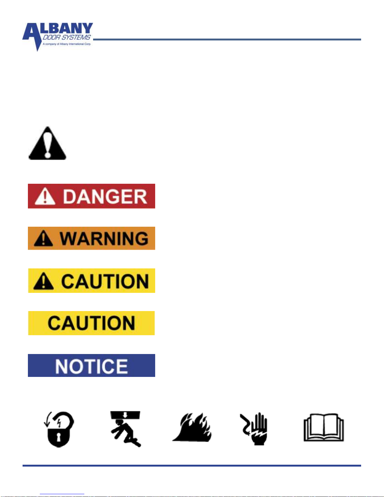
WARNING
Do not install, operate or service the product unless you have read and understand
the safety practices, warnings, installation and maintenance instructions contained
in this manual.
Albany Door Systems - A Company of Albany International Corp. All Rights Reserved
1080 Maritime Drive, Port Washington, WI 53074 - 975-A Old Norcross Road, Lawrenceville, Georgia 30045
262-268-9885 or 877-9252468
v4202010
STATEMENT OF WARRANTY

Rev. 4/9/2010 Manual #001449 2
High Speed Doors
Operation
TABLE OF CONTENTS
ALBANY DOOR SYSTEMS CONTACT INFORMATION
Port Washington, WI
1080 Maritime Drive, Port Washington, WI 53074
Phone: 262-268-9885 Fax: 262-268-9895
Technical Support: 262-268-9885
Lawrenceville, GA
975 A Old Norcross Road, Lawrenceville, GA 30046
Phone: 800-252-2691 Fax: 262-268-9895
Technical Support: 262-268-9885
3Introduction
4Product Description
7Service & Repair
14Troubleshooting
5Safety Advice
19Drawings
23Mechanical Procedures
31Maintenance

3 Manual #001449 Version 4.2
INTRODUCTION
The contents of this manual are designed to help you operate and maintain Albany UltraTough™
high speed doors. DO NOT operate or perform maintenance on the high speed door unless
you have read through the instructions in this manual.
The safety alert symbol is used to identify safety information about hazards that can
result in personal injury. A signal word (DANGER, WARNING, or CAUTION) is
used with the safety alert symbol to indicate the likelihood and the potential severity
of injury. In addition, a hazard symbol may be used to represent the type of hazard.
DANGER indicates a hazard that, if not avoided, will
result in death or serious injury.
WARNING indicates a hazard that, if not avoided,
could result in death or serious injury.
CAUTION indicates a hazard that, if not avoided,
might result in minor or moderate injury.
CAUTION, when used without the alert symbol, indi-
cates a situation that could result in damage to the
door.
NOTICE is used to inform you of a method, refer-
ence, or procedure that could assist with specific
operations or procedures.
Other symbols that may be used in this manual are:
Lock Out / Tag Out Crushing Fire Shock Read Manual

Rev. 4/9/2010 Manual #001449 4
High Speed Doors
Operation
Product description
Function and design of this door
The model Re-Coil-Away is a vertically opening door.
Principle
The door assembly consists of left and right side frames and a header assembly. The header as-
sembly contains the curtain and the drive system already attached. The bottom beam is already at-
tached to the curtain. Door comes standard with a balance system and also available as an unbal-
anced option.
The Re-Coil-Away door rolls the curtain material directly on and off a barrel assembly. The edges of
this curtain are contained within the side frames via a patented windlok system while the curtain is
being rolled or unrolled off the barrel. These side frames guide the curtain also and provide a seal.
The bottom beam, located on the bottom of the curtain, contains a continuously monitored electrical
safety edge. Activation of this device will stop the door and cause the door to reverse to a fully open
position. The door also has a reversing photocell attached to the side frames of the door.
Control Unit
The Re-Coil-Away may be driven with the control unit ACS-50, UltraSmart or PLC with contactors.
The maximum opening speed depends on the size of the door and type of motor. See applicable
control panel manual for door operation and electrical troubleshooting guides.
Electric safety features
The Re-Coil-Away door utilizes a minimum of two safety features. This is comprised of safety photo-
cells and electric reversing edge.
Additional Safety systems
Depending on the kind of application it may be useful to have additional sensors as safety features.
This is especially true for a door with a high volume of human traffic or with low sized doors with a
height under 10 feet (3m).
Albany Door Systems offers a variety of safety systems for high-speed doors. Some examples could
be any of the following: Light beam barriers, motion detectors, induction loops. For any other electri-
cal requirement contact us at the factory.
Drives
The Re-Coil-Away is operated with an electrical drive. Drive side is chosen by the end-user. The
drive system could be either 1-speed or 2-speed depending on door size and customer require-
ments. The drive systems come in 3 different operating voltages: 208-240VAC, 440-480VAC, and
550-600VAC.

5 Manual #001449 Version 4.2
Technical Data
Door principle: Roll door
Running direction: Vertical
Application: External door
(also applicable as interior door)
Maximum Sizes: 24‟ wide x 27‟ high
Maximum opening speed: 48 inches per second @ 8 feet
(Depends on door size)
Maximum Closing speed: 24 inches per second @ 8 feet
(Depends on door size)
Fitting position: Interior or external mounting
Drive: Electrical
Electric Power: 240VAC, 440VAC, 575VAC
Maximum Horse power: 2.7 H.P.
Control unit options: ACS-50 / UltraSmart / PLC
Control voltage 24VDC
Motor protection category: IP54 - NEMA 12
Door frame: Painted Steel
Curtain: SBR, EPDM
Door dimensions and fitting space See enclosed technical drawing
Fixing points: See fixing drawings
Technical changes resulting of product maintenance are subject to
alterations
Safety advice
Area of application
The Albany Re-Coil-Away is used for the closing of door openings preferably in industrial buildings
that are highly used area of automobiles or heavy equipment.
It is a flexible exterior door with resistance to wind and weather conditions. It opens with a speed
that is especially suitable for heavy traffic throughways. It ensures a smooth transport flow and re-
duces collisions. The Albany Re-Coil-Away door may also be applied to interior areas.

Rev. 4/9/2010 Manual #001449 6
High Speed Doors
Operation
Responsibilities of the operator
The Albany Re-Coil-Away door is designed and manufactured under consideration of safety techni-
cal specifications. This meets the highest standard of safety.
However, this safety can only be reached in operational practice if all necessary measures are met.
It is the duty of the operator of such door system to ensure all these measures and check it‟s status.
Please read the operation manual carefully and keep it in a safe place.
The operator of the door is held to ensure especially that:
Installation, first operation, inspection, servicing, repair work and dismantling are only done by
personnel that have been trained by the manufacturer.
Only to be operated by personnel that have been sufficiently assigned and authorized to operate
this door system.
The door is only used according to the determined application (see above).
The door must be only operated in a functional perfect state and especially the safety features
must be checked for function in regular intervals.
The operation manual should be kept at the site of the fitted door system in readable condition.
All safety and warning labels should not be removed from the machine and should also be kept
readable.
Do not drive through the door opening unless door is completely open.
In power loss condition the electrical drive for the door curtain can be unlocked using the disen-
gagement chains and then the curtain hand chained upwards. When the disengage lever has
been engaged the control system has been disable.
During operation of the door do not stick your hands in the side frames. Keep hands and feet
clear of the door at all times. Stay clear of the door while it is operating.
Human traffic should be avoided within the working area of the door. Existing side doors for hu-
man traffic should be used instead.
Do not run through the door opening. Go upright and with normal pace.
Keep the working vicinity and the opening of the door in clear of obstructions. Maintain a clear
door opening at all times. Obstructions may cause accidents.
Do not climb up the door
For all kind of work on the door the main switch (main disconnect) must be set to the OFF posi-
tion and locked out to prevent power from being reset.
When damage occurs to the door (mechanically or electrically) turn off operational power imme-
diately. This is especially true if you have damage of the curtain or drive system.
USE EXTREME CAUTION when it is necessary to service the control panel or the auxiliary con-
trol box while it is energized. The door must only be operated with the correct voltage and fre-
quency.
Use only the auxiliaries and devices authorized by the manufacturer of the door.
The STOP Button on the front of the panel is a momentary stop ONLY with the ACS-50 and Ul-
traSmart panels. The door will only stop for that cycle; motion detectors, floor loops, or any
activating device can activate the door! To ensure that the door keeps from being activated,
use the rotary disconnect on the front of the panel.
DO NOT EVER USE PETROLUM BASED PRODUCTS ON THE CURTAIN, IF DONE THIS
VOIDS ALL WARRANTY ON THE CURTAIN MATERIAL.
Pay attention to the general safety advises mentioned under the core point SAFETY but also the
special safety advises mentioned in the other chapters of the operation manual.

7 Manual #001449 Version 4.2
Service & Repair
Customer Service
In case of door maintenance/malfunctions or repair work, please contact the supplier or the manu-
facturer.
Address of Customer Services Department
1080 Maritime Drive, Port Washington, WI 53074
Phone: 262-268-9885 Fax: 262-268-9895
Technical Support: 262-268-9885
Inspection and maintenance
Before starting work on the door, the power must be disconnected by switching off the main power
disconnect and then locked out. Then the control box needs to be checked to verify that voltage
has been eliminated from the panel. Please observe that all used ladders, scaffoldings, or such,
correspond with the valid safety regulations.
The working area must be blocked for both vehicle and foot traffic. Lubrication oil on the floor, tools
and other material should be removed from the floor when work has been finished.
The necessary maintenance inspections, check-up and time intervals are listed in the
Inspection section.
Cleaning and maintenance of the door curtain
Do not ever use any petroleum-based products on the curtain.
Clean curtain with a citrus based cleaner or a cleaner specifically designed for cleaning SBR /
EPDM rubber materials. All cleaners are to be petroleum free and non-caustic.
Dust may be removed with a cloth. Harder dirt may be removed with water. Dirt, grease, or oil
on metal may be removed with a citrus cleaner.

Rev. 4/9/2010 Manual #001449 8
High Speed Doors
Operation
Inertia Brake GFA FG220-15-60
Lock-Out Tag-out all electrical power supplied to the door before making
any electrical installations or connections. Also Lock-out Tag-out any
equipment near the installation site if that equipment may be inadvertently
operated into the area used to assemble and install the door. Failure to
properly deenergize electrical circuits and disable equipment during in-
stallation and/or maintenance could result in death or serious injury.

9 Manual #001449 Version 4.2
Activation - Repair - Replacement

Rev. 4/9/2010 Manual #001449 10
High Speed Doors
Operation

11 Manual #001449 Version 4.2

Rev. 4/9/2010 Manual #001449 12
High Speed Doors
Operation

13 Manual #001449 Version 4.2
The picture shows all the
parts that are included in
the dampening plate repair
kit.
Situation B described in the
previous pages would be
the only time that a repair
kit would be needed.
6622T0023 Dampening plate repair kit

Rev. 4/9/2010 Manual #001449 14
High Speed Doors
Operation
Troubleshooting
How to Wedge a Curtain
Why would a curtain need a wedge?
A wedge is used to correct uneven curtain build, which can be evidenced by the following symp-
toms:
(a) Bottom bar tracks to either right or left thereby causing it to jam against the guide,
(b) Bottom bar becomes out-of-level when door is in the open position,
(c) Curtain tends to 'cone' in one direction on the barrel, as the door is rolling up.
What is a wedge?
A wedge is a piece of waste rubber (can be as large as 6" square by as much as 1/2" thickness),
which is strategically placed on the drive barrel between the curtain and the barrel. It is secured
with a self-tapping screw(s).
How to determine where to fasten a wedge.
It is normal for a curtain to 'float' slightly from side to side as the door rolls up and down. Wedging
is required only when there is a severe tracking problem such as listed above.
The placement of a wedge can be determined in several ways. For example, if the bottom bar
were tracking to the left as the door is opening, then the wedge would be fastened on the right end
of the barrel. The wedge would then make the curtain roll-up faster on the right side, thus making
the bottom bar track evenly between the guides. Should the door be tracking to the right, and then
obviously the wedge should be fastened to the left end of the barrel.
It is important to identify whether a door requires a wedge or if it has been installed out-of-level.
For instance, if a door rolls down with the bottom bar continually tracking to one side, eventually
jamming near the floor, yet the curtain does not appear to 'cone', then the door is most likely out-of-
level. To remedy the problem, it may be necessary to raise one of the end plates (which have slot-
ted holes) to level the door.

15 Manual #001449 Version 4.2
Removal and Re-installation of curtain in guides
1. Unbolt the hinged front guide plates of both the left and right guides. Swing the front guide
plates open and place them to the side.
1 In the event that only the upper portion is hinged, raise the curtain and bottom bar until the bot-
tom bar front angle is just below the open hinged portion. Then, lift the curtain one end at a
time, out of the guides and set it outside the front guide plates.
2 Lower the curtain slowly and make sure that it does not catch on the guides. To re-install the
curtain, follow the above steps in reverse order. Be sure to close and bolt the front guide plates
prior to putting the door back into operation. Make sure that the guide gap is an even ½” from
top to bottom.
Removal and Re-installation of bottom bar
1. With the curtain and bottom bar supported on a flat surface, remove the bolts which secure the
bottom bar to the curtain.
2. Slip the curtain out of the bottom bar. To re-install the curtain back into the bottom bar, follow
the above steps in reverse order.
If the bottom bar is equipped with an electric reversing edge, be sure to unplug the connector when
removing the bottom bar. In addition, take extreme care not to damage the electric reversing edge
fabric. A puncture would allow moisture to penetrate it, thus causing premature failure of the re-
versing edge.
Repairs to rubber curtain –rips or perforations
In order to work on the ripped or perforated area, the curtain must be taken out of the guides and
lowered to the floor. Then, either work on an area supported by the floor or alternatively, a solid,
level surface provided by a heavy table, for example. Refer to Figure 31 and 32 for positioning of
the curtain prior to repairing it.
1. Using a utility knife, set it to a depth that will penetrate the rubber down to the nylon cord centre
of the curtain and cut a rectangular or square section approximately 2" wider than the sides of
the rip or perforation. Be careful not to cut the nylon cord itself (see Figure 31).
2. Using a screwdriver and pliers and starting at one corner of the cut, peel the surface from the
nylon cord centre within the perimeter of the cut.
3. Using coarse sandpaper or a wire brush, remove loose rubber particles from the nylon cord
centre. However, it is not necessary to have the fabric 100% bare.
4. Flip the curtain over to the other side of the rip or perforation and repeat Step 1 through Step 3.
5. From the 1/8" thick piece of repair rubber, cut some pieces to inlay into the prepared areas. Us-
ing a grinder with a sanding disc or a wire brush, roughen-up the inlay surfaces for bonding.
6. Mix the adhesive as per the manufacturer's instructions and apply a liberal coating to the nylon
cord fabric and the rough surfaces of the inlay rubber segments. Allow pieces to dry to the
touch (about 15 to 20 minutes) and apply a second coating. Allow to set until tacky. Place the
inlay segments into position and, using a rubber or rawhide mallet and a steel buckler, impact
the entire area of the patch repeatedly. A high degree of impact ensures proper adhesion.
Clamping is not acceptable. Allow the cement to cure thoroughly (1-1/2to 2 hours) before mov-
ing the curtain.
7. Finally, raise the curtain to an open position, re-insert it into the guides, close and re-bolt the
guides, and resume normal operation.

Rev. 4/9/2010 Manual #001449 16
High Speed Doors
Operation

17 Manual #001449 Version 4.2
Maintenance Schedule
Due to the unique design features of your new "RE-COIL-AWAY", the need for continual mainte-
nance normally associated with conventional door systems (i.e.: guide rollers, hinges, door track,
etc.) is virtually eliminated. The limited maintenance procedures listed below, when completed as
indicated, will assure many years of trouble-free operation.
MAINTENANCE
PROCEDURE
INITIAL
1,500 CY-
CLES
EVERY 25,000
CYCLES OR 3
MONTHS
EVERY 100,000 CYCLES
OR 12 MONTHS
LUBRICATE:
Flange Bearing (4)
Drive Chain
NO
NO
NO
OIL
Grease, 1 shot
OIL
ADJUSTMENTS:
(check & adjust if neces-
sary)
Drive Chain Tension
Guides, bottom bar &
header assembly for
rust or damage
Guide Opening 1/2"
All Fasteners (check
for tightness)
Limit Settings
Reversing Edge
(check for proper op-
eration and any signs
of damage)
YES
YES
NO
YES
YES
YES
YES
YES
YES
YES
YES
EVERY MONTH
YES
YES
YES
YES
YES
YES

Rev. 4/9/2010 Manual #001449 18
High Speed Doors
Operation
Gearbox
The gear construction is maintenance-free and has lifetime lubrication. (The output shaft should be
kept rust free.)
Torque Specifications
The table below list the type of bolt, its use, and what its torque setting is
Size Type Location Torque (ft-
lb):
5/8-11 x 2" Hex head bolt,
Grade 8 Drive barrel bearing to end plate 212
5/8-11 x 1-1/2" Hex head bolt,
Grade 8 End plate to side frame 212
5/8-11 x 1-1/2" Hex head bolt,
Grade 8 End plate to inertia brake bracket 212
5/8-11 x 1-1/2" Hex head bolt,
Grade 8 End plate to spring mounting
brackets 212
1/2-13 x 2" Hex head bolt,
Grade 8 Idler barrel bearing to end plate 106
1/2-13 x 1-1/2" Hex head bolt,
Grade 8 Header assembly to truss/
spreader bars 106
1/2-13 x 1-1/2" Hex head bolt,
Grade 8 Inertia brake bracket
to inertia brake 106
M16x2.0x40mm T-bolt Operator to T-slot rail
(Large operator) 59
M12x1.75x30mm T-bolt Operator to T-slot rail
(Small operator) 89
3/8-16 x 1-1/2" Hex head bolt,
Grade 5 Side frame angle to front cover 31
3/8-16 x 1" Socket head cap screw,
grade 5 Bottom beam
to aluminum extrusion 31
3/8-16 x 1-1/4" Button head screw,
Grade 5 Bottom beam angle
thru fabric to flat bar 31
5/16-18 x 1-1/2" Self tapping screw Curtain to drum tube 15
1/4-20 x 1-1/4" Hex head bolt,
Grade 5 Break away bar on bottom beam 8

19 Manual #001449 Version 4.2
M&I Re-Coil-Away Architectural Over 12’ x 12’ (Balanced)
This manual suits for next models
2
Table of contents
Other Albany Door manuals
Popular Door manuals by other brands

Pella
Pella 80KM0103 installation instructions

Sterling Plumbing
Sterling Plumbing Frameless Bypass Shower Door SP5465-45 Specification sheet

Sterling Plumbing
Sterling Plumbing Pivot Shower Doors 950C Series Specifications

RYTEC
RYTEC Turbo-Slide owner's manual

Sterling Plumbing
Sterling Plumbing VISTA PIVOT II 1505D-48 Specifications

Gianni Industries
Gianni Industries Micro Surface specification