4
Contents
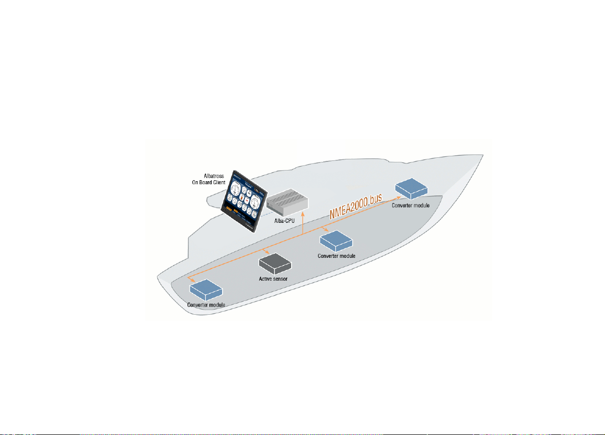
1. Introduction...................................................................................................................................5
2. Specifications ...............................................................................................................................6
3. Quick installation ..........................................................................................................................7
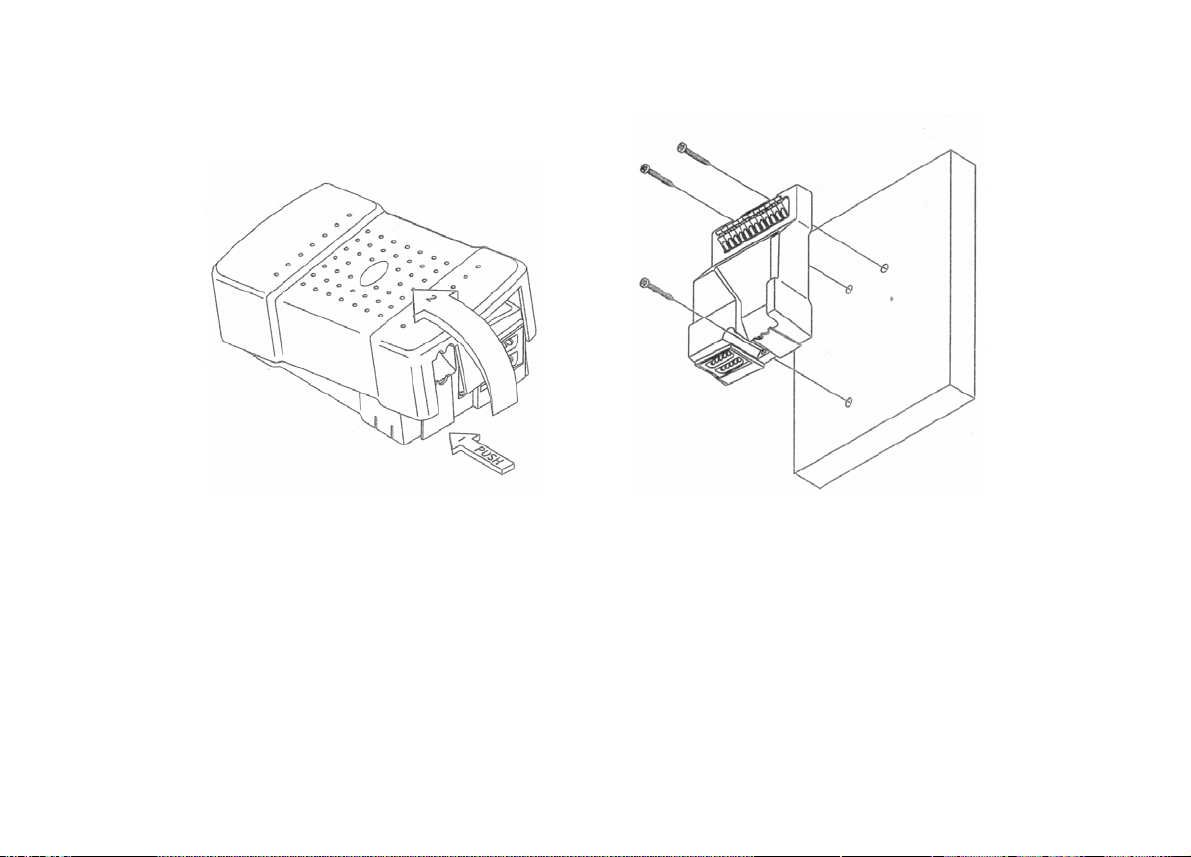
3.1. Unpacking the unit ....................................................................................................................7
3.2 Choosing a location to mount the module..................................................................................8
3.2.1. Module location if analogue gauges are already present...................................................8
3.2.2. Module location when the vessel contains analogue gauges………………………………10
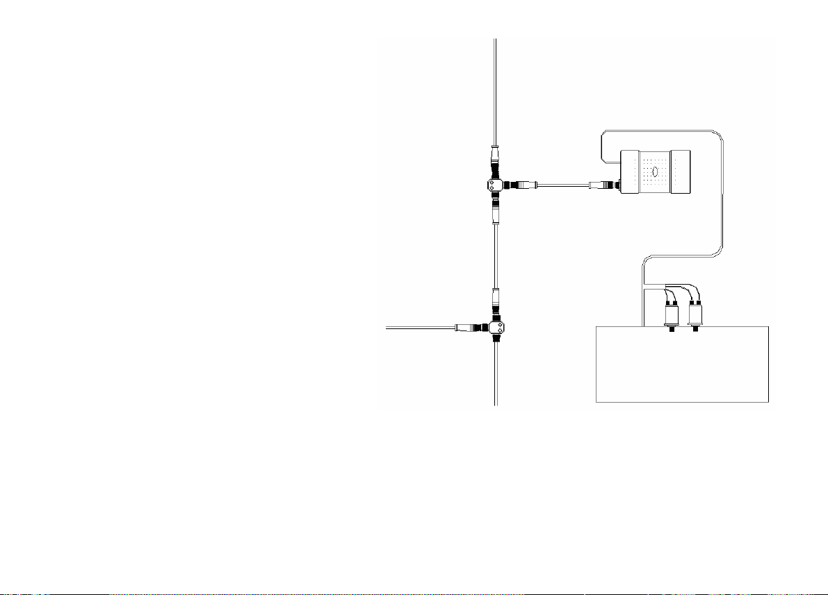
3.3 Alba-Engine Connections.........................................................................................................12
3.3. Conexiones del Alba-Engine...................................................................................................12
3.3.1 Alba-Engine connection to a motor with VDO analogue gauges.......................................13
3.3.2 Alternator and mass connection........................................................................................15
3.3.3 Alba-Engine connection to a motor with no control panel..................................................16
3.3.4 Conexión al bus NMEA2000 .............................................................................................17
3.4 Alba-Engine Configuration .......................................................................................................20
3.4.1 NMEA instance number and address................................................................................21
3.4.2 Sensor calibration and commercial brand choice..............................................................25
3.4.3 Custom sensor calibration.................................................................................................26
3.7 Technical specifications...........................................................................................................27
3.8 Technical support.....................................................................................................................28
4
Contents
1. Introduction...................................................................................................................................5
2. Specifications ...............................................................................................................................6
3. Quick installation ..........................................................................................................................7
3.1. Unpacking the unit ....................................................................................................................7
3.2 Choosing a location to mount the module..................................................................................8
3.2.1. Module location if analogue gauges are already present...................................................8
3.2.2. Module location when the vessel contains analogue gauges………………………………10
3.3 Alba-Engine Connections.........................................................................................................12
3.3. Conexiones del Alba-Engine...................................................................................................12
3.3.1 Alba-Engine connection to a motor with VDO analogue gauges.......................................13
3.3.2 Alternator and mass connection........................................................................................15
3.3.3 Alba-Engine connection to a motor with no control panel..................................................16
3.3.4 Conexión al bus NMEA2000 .............................................................................................17
3.4 Alba-Engine Configuration .......................................................................................................20
3.4.1 NMEA instance number and address................................................................................21
3.4.2 Sensor calibration and commercial brand choice..............................................................25
3.4.3 Custom sensor calibration.................................................................................................26
3.7 Technical specifications...........................................................................................................27
3.8 Technical support.....................................................................................................................28